EP1349760B1 - Hauptzylinderkolben und vorrichtung zur befestigung eines rückschlagventils darin - Google Patents
Hauptzylinderkolben und vorrichtung zur befestigung eines rückschlagventils darin Download PDFInfo
- Publication number
- EP1349760B1 EP1349760B1 EP01999498A EP01999498A EP1349760B1 EP 1349760 B1 EP1349760 B1 EP 1349760B1 EP 01999498 A EP01999498 A EP 01999498A EP 01999498 A EP01999498 A EP 01999498A EP 1349760 B1 EP1349760 B1 EP 1349760B1
- Authority
- EP
- European Patent Office
- Prior art keywords
- cage
- housing
- piston
- flap
- retaining means
- Prior art date
- Legal status (The legal status is an assumption and is not a legal conclusion. Google has not performed a legal analysis and makes no representation as to the accuracy of the status listed.)
- Expired - Lifetime
Links
- 238000002788 crimping Methods 0.000 claims description 7
- 238000000034 method Methods 0.000 claims 2
- 239000012530 fluid Substances 0.000 abstract description 2
- 230000000284 resting effect Effects 0.000 abstract 1
- 239000007788 liquid Substances 0.000 description 7
- 229910052751 metal Inorganic materials 0.000 description 5
- 239000002184 metal Substances 0.000 description 5
- 239000002245 particle Substances 0.000 description 3
- 229910000831 Steel Inorganic materials 0.000 description 2
- 230000006835 compression Effects 0.000 description 2
- 238000007906 compression Methods 0.000 description 2
- 238000006073 displacement reaction Methods 0.000 description 2
- 238000007789 sealing Methods 0.000 description 2
- 239000010959 steel Substances 0.000 description 2
- 229910000838 Al alloy Inorganic materials 0.000 description 1
- XAGFODPZIPBFFR-UHFFFAOYSA-N aluminium Chemical compound [Al] XAGFODPZIPBFFR-UHFFFAOYSA-N 0.000 description 1
- 230000000694 effects Effects 0.000 description 1
- 229910001234 light alloy Inorganic materials 0.000 description 1
- 230000000717 retained effect Effects 0.000 description 1
Images

Classifications
-
- B—PERFORMING OPERATIONS; TRANSPORTING
- B60—VEHICLES IN GENERAL
- B60T—VEHICLE BRAKE CONTROL SYSTEMS OR PARTS THEREOF; BRAKE CONTROL SYSTEMS OR PARTS THEREOF, IN GENERAL; ARRANGEMENT OF BRAKING ELEMENTS ON VEHICLES IN GENERAL; PORTABLE DEVICES FOR PREVENTING UNWANTED MOVEMENT OF VEHICLES; VEHICLE MODIFICATIONS TO FACILITATE COOLING OF BRAKES
- B60T11/00—Transmitting braking action from initiating means to ultimate brake actuator without power assistance or drive or where such assistance or drive is irrelevant
- B60T11/10—Transmitting braking action from initiating means to ultimate brake actuator without power assistance or drive or where such assistance or drive is irrelevant transmitting by fluid means, e.g. hydraulic
- B60T11/16—Master control, e.g. master cylinders
- B60T11/232—Recuperation valves
Definitions
- the invention relates to a piston of a master cylinder of a braking circuit, in particular for a motor vehicle, and a device for mounting a valve in this piston.
- the primary and secondary pistons are each equipped with a valve for opening and closing a passage of pressurized liquid formed in the piston, depending on the displacements of the piston. in the master cylinder.
- This liquid passage opens axially into a housing formed at one end of the piston and in which is received the valve which comprises a rod guided in the liquid passage and a head located outside the passage and biased by a return spring to the outlet of the liquid passage to seal the latter in a sealed manner.
- This return spring is a "compression spring mounted between the valve head and bearing means reported on the piston.
- the cage comprises at its periphery resiliently deformable tabs oriented radially outwardly and intended to engage and lock in an annular groove of the cylindrical wall of the housing of the valve.
- these tabs are elastically close to the axis when the cage is inserted into the housing of the valve and they rub on the cylindrical wall of the housing until the cage is in an axial position inside the housing where the tabs engage by elastic expansion in the aforementioned annular groove.
- the invention aims in particular to provide a simple solution, effective and inexpensive to this problem by avoiding any risk of scratches and leaks of the master cylinder that would result from mounting the aforementioned cage on the piston of the master -cylinder.
- a master cylinder piston in particular for a motor vehicle, comprising at one end a substantially cylindrical housing for receiving a valve and a return spring mounted between the valve and a cage attached to the piston, characterized in that this cage is fixed by crimping inside said housing.
- Crimping is a plastic deformation of a part of the cage, which can be performed when the cage is in a desired axial position to inside the housing, without the risk of tearing particles or metal chips that may cause scratches and leaks in the master cylinder
- crimping is performed by retaining means which are formed on the cage and engaged by plastic deformation in an annular groove of said housing.
- the cage retaining means comprise a substantially cylindrical rim which extends around the cage in the direction of the open end of the housing.
- these retaining means comprise lugs which extend substantially parallel to the axis of the cage around it in the direction of the open end of the housing.
- these tabs are formed by punctured or by cutting a substantially cylindrical or frustoconical wall of the cage.
- the retaining means are formed at one end of the cage and are connected thereto by an annular flange extending radially inwards and comprising means of application on bearing means formed in the flap housing.
- the cage At its end opposite to said retaining means, the cage comprises another annular flange which is oriented radially inwards and which forms bearing means of the return spring of the valve.
- the cage according to the invention is advantageously made by stamping, simply and economically.
- the means for supporting and applying the cage to the support means of the housing comprise a central pusher, mounted in a tubular member whose chamfered end forms the aforementioned means of radial deformation.
- the central pusher is guided in axial sliding in the aforementioned tubular member and is biased by a return spring in a direction corresponding to the application of the cage on the support means formed in the housing.
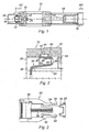
- FIG 1 schematically shows an exemplary embodiment of a secondary piston 10 of a tandem master cylinder of a braking circuit for a motor vehicle, the piston 10 comprising a body 12 connected by a set screw 14 to a stop of spring 16 biased by a spring 18 mounted between the stop 16 and one end of the body 12 of the secondary piston, this spring stop 16 being intended to cooperate with a primary piston (not shown) of the master cylinder.
- the secondary piston comprises a tubular axial end 20 forming a substantially cylindrical housing for receiving a valve 22 for opening and closing an axial passage 24 formed in a transverse wall of the body 12.
- the valve 22 comprises an axial rod 26 engaged in the passage 24 and is associated with a return spring 28 mounted between the head of the valve 22 and a cage 30 attached inside the housing 20.
- valve head 22 In the position represented in figure 1 , the valve head 22 is elastically pushed by the return spring 28 bearing on the outlet of the passage 24 in the housing 20 and closes the passage sealingly.
- the cage 30 is a metal part, for example of steel, made by stamping and comprises a frustoconical wall 32 widening towards the rear and whose front end is connected to an annular flange 34 extending radially towards' the inside, the rear end of the frustoconical wall 32 being connected to an annular flange 36 extending radially outwardly and connected itself to a cylindrical flange 38 which extends forward, around and distance from the frustoconical wall 32.
- the front end 40 of the cylindrical flange 38 is deformed radially outwards and extends obliquely to abut on the front edge 42 of an annular groove 44 formed in the inner surface of the wall of the housing 20, this groove having a rear edge 46 which extends obliquely rearwardly.
- the internal diameter of the cylindrical wall of the housing 20 is slightly greater than the external diameter of the cylindrical rim 38 in the unstressed free state.
- the cage 30 is axially displaceable in the housing 20 by a distance that corresponds to the axial clearance of the end 40 of the flange 38 in the groove 44, which allows the bottom of the housing 20 to be clear of the orifices 48 formed in FIG. regular intervals in the annular flange 36 to facilitate the flow of the pressurized liquid through the passage 24 when the valve 22 is in the open position, the pressurized liquid also passing through the central orifice defined by the annular flange 34 of the cage 30.
- FIG. 3 An exemplary embodiment of the mounting device of the cage 30 is shown schematically in figure 3 .
- This device 50 comprises a central pusher 52 which is slidably mounted inside a tubular member 54 whose rear end 56 is chamfered externally and constitutes the means of plastic deformation of the end 40 of the cylindrical rim 38 of the cage 30.
- a compression spring 58 is mounted inside the tubular member 54, between the pusher 52 and a front stop 60 axially adjustable in position by screwing inside the tubular member 54, the pusher 52 being thus solicited continuously towards the rear by the spring 58 and being brought into abutment on an internal shoulder 62 of the tubular member 54.
- the rear end of the pusher 52 comprises means for supporting the cage 30,
- this mounting device is illustrated in figure 4 , whose lower part represents the cage 30 before its crimping and the upper part the cage 30 being crimped.
- valve 22 is engaged by its rod 26 in the passage 24 and the spring 28 is engaged on the head of the valve 22.
- the mounting device of the figure 3 is aligned axially with the secondary piston 10 to present the cage 30 carried by the end of the pusher 52 facing the open end of the housing 20 at the front end of the piston 10. Then the device is moved in axial translation until in the position shown in the lower part of the figure 4 where the spring 28 is compressed between the valve head 22 and the rim annular 34 of the cage 30, the latter being supported by its annular rim 36 on an inner shoulder 64 of the housing 20. In this position, the front end of the cylindrical rim 38 of the cage 30 is substantially at the level of the part median of the annular groove 44 of the housing 20.
- the tubular member 54 of the mounting device continues to be displaced in axial displacement so that its chamfered end 56 is introduced inside the cylindrical rim 38, deforming radially outwardly the end 40. this rim inside the annular groove 44, and comes into axial abutment on the annular flange 36 of the cage 30, which is itself abutted on the inner shoulder 64 of the housing 20, as shown in the half superior of the figure 4 .
- the translation device 50 is moved in axial translation forward to leave the housing 20.
- the cage 30 follows this movement forward until that the end 40 of its cylindrical rim 38 bears on the front edge of the annular groove 44 in the position shown in FIG. figure 2 .
- the valve 22 is held in sealed sealing position of the passage 24 and can be moved in translation forward by compressing the spring 28 for the opening of this passage.
- the cage 30 comprises a cylindrical or frustoconical wall 32 whose rear end is formed with U-shaped lugs 66, a first portion 68 of which extends axially rearward, in the extension of the wall 32, of which an intermediate portion 70 is folded radially outwardly and performs the function of the annular flange 36 of the embodiment of the figure 2 and of which a third portion 12 extends axially forward and performs the function of the cylindrical flange 38 of the embodiment of the figure 2 .
- the wall 32 is connected to an annular rim 34 as in the previous embodiment.
- the cage 30 comprises a wall 32 which is frustoconical at least in its rear part and which may be cylindrical in its front part, and tabs 74 which are formed by punctures of the rear part of the wall 32, these tabs 74 extending forwards substantially parallel to the axis of the cage from the rear end thereof and over a length corresponding to that of the cylindrical flange 38 of the embodiment of the figure 2 .
- the cage At its front end, has an annular rim 34 oriented radially inwards, as in the previous embodiments.
- the variant embodiment of the cage represented in Figures 7 and 8 essentially corresponds to the embodiment of the figure 2 and comprises a frustoconical wall 32 which extends between a front annular flange 34 and a rear annular flange 36 having orifices 48 and connected to a cylindrical flange 38, the rear annular flange 36 further comprising projecting studs 76 extending axially towards the rear and which form the abutment means of the cage 30 on the internal shoulder 64 of the housing 20.
- fixing the cage 30 inside the housing 20 is performed in the aforementioned manner, avoiding contact with the inner wall of the housing 20 and the edges and the bottom of the annular groove 44 to avoid any risk of tearing particles or metal chips.
Landscapes
- Engineering & Computer Science (AREA)
- Transportation (AREA)
- Mechanical Engineering (AREA)
- Transmission Of Braking Force In Braking Systems (AREA)
- Hydraulic Clutches, Magnetic Clutches, Fluid Clutches, And Fluid Joints (AREA)
- Portable Nailing Machines And Staplers (AREA)
- Pistons, Piston Rings, And Cylinders (AREA)
- Valve-Gear Or Valve Arrangements (AREA)
- Valve Housings (AREA)
Claims (12)
- Hauptzylinderkolben, insbesondere für ein Kraftfahrzeug, der an einem Ende eine zylindrischen Aufnahme (20) zum Aufnehmen eines Ventilelements (22) und einer Rückstellfeder (28) aufweist, welche zwischen dem Ventilelement und einem an den Kolben angesetzten Halter (30) angeordnet ist, dadurch gekennzeichnet, dass der Halter (30) durch Verstemmen befestigt ist, indem am Halter ausgebildete Haltemittel (38, 72, 74) in der Aufnahme (20) plastisch verformt werden.
- Kolben nach Anspruch 1, dadurch gekennzeichnet, dass das Verstemmen durch plastische Verformung der Haltemittel (38, 72, 74) in einer ringförmigen Nut (44) der Aufnahme durchgeführt wird.
- Kolben nach Anspruch 1 oder 2, dadurch gekennzeichnet, dass der Halter (30) in der Aufnahme über eine Entfernung verschiebbar ist, die dem axialen Spiel seiner Haltemittel in der ringförmigen Nut (44) entspricht.
- Kolben nach Anspruch 1, 2 oder 3, dadurch gekennzeichnet, dass die Haltemittel einen im Wesentlichen zylindrischen Rand (38) umfassen, der sich um den Halter zum offenen Ende der Aufnahme (20) hin erstreckt.
- Kolben nach Anspruch 1, 2 oder 3, dadurch gekennzeichnet, dass die Haltemittel Laschen (72, 74) umfassen, die sich im Wesentlichen parallel zur Achse des Halters um diesen herum und zum offenen Ende der Aufnahme (20) hin erstrecken.
- Kolben nach Anspruch 5, dadurch gekennzeichnet, dass die Laschen (72, 74) durch Ausstanzen oder durch Einschnitte einer im Wesentlichen zylindrischen oder kegelstumpfartigen Wand (32) des Halters gebildet sind.
- Kolben nach einem der vorhergehenden Ansprüche, dadurch gekennzeichnet, dass der Halter (30) auf der Seite des Ventilelements (22) Mittel (36, 76) zur Abstützung an einem Innenabsatz (64) der Aufnahme aufweist.
- Kolben nach einem der vorhergehenden Ansprüche, dadurch gekennzeichnet, dass das Ende des Halters, das sich auf der Seite des offenen Endes der Aufnahme (20) befindet, einen ringförmigen Rand (34) aufweist, der sich radial nach innen erstreckt und Mittel zur Abstützung der Feder (28) zum Zurückstellen des Ventilelements bildet.
- Kolben nach einem der vorhergehenden Ansprüche, dadurch gekennzeichnet, dass der Halter durch Tiefziehen gebildet ist.
- Vorrichtung zum Anbringen eines Ventilelements in einem Kolben eines Hauptzylinders, insbesondere für ein Kraftfahrzeug, wobei dieser Kolben (10) an einem Ende eine im Wesentlichen zylindrische Aufnahme (20) zum Aufnehmen eines Ventilelements (22) und einer Rückstellfeder (28) aufweist, welche zwischen dem Ventilelement und einem Halter (30) angebracht ist, der an den Kolben angesetzt und über Haltemittel befestigt ist, die in eine ringförmige Nut (44) der zylindrischen Wand der Aufnahme (20) eingreifen, dadurch gekennzeichnet, dass:- der Halter (30) in einem freien Ausgangszustand einen Außendurchmesser besitzt, der kleiner ist als der Innendurchmesser der Aufnahme (20),- die Aufnahme (20) Mittel (64) für die axiale Abstützung des Halters (30) in einer Stellung aufweist, in welcher seine Haltemittel (38, 72, 74) radial auf die vorgenannte ringförmige Nut (44) ausgerichtet sind,- die Montagevorrichtung Mittel (52) zum Tragen und Anlegen des Halters (30) an die Stützmittel (64) der Aufnahme und Mittel (54) zur radialen Verformung der Haltemittel des Halters nach außen aufweist, damit diese in die ringförmige Nut (44) der Aufnahme eingreifen.
- Vorrichtung nach Anspruch 10, dadurch gekennzeichnet, dass die Mittel zum Anlegen des Halters (30) an die Stützmittel (64) der Aufnahme eine mittlere Drückeinrichtung (52) aufweisen, die in einem rohrförmigen Element (54) angebracht ist, bei dem ein abgeschrägtes Ende (56) die vorgenannten Mittel zur radialen Verformung bildet.
- Vorrichtung nach Anspruch 11, dadurch gekennzeichnet, dass die mittlere Drückeinrichtung (52) im rohrförmigen Element (54) in eine axiale Gleitbewegung geführt und durch eine Rückstellfeder (58) in eine Richtung beaufschlagt ist, die dem Anlegen des Halters (30) an die Stützmittel (64) der Aufnahme entspricht.
Applications Claiming Priority (3)
| Application Number | Priority Date | Filing Date | Title |
|---|---|---|---|
| FR0015848 | 2000-12-06 | ||
| FR0015848A FR2817522B1 (fr) | 2000-12-06 | 2000-12-06 | Piston de maitre-cylindre et dispositif de montage d'un clapet dans ce piston |
| PCT/FR2001/003807 WO2002046010A1 (fr) | 2000-12-06 | 2001-12-03 | Piston de maitre-cylindre et dispositif de montage d'un clapet dans ce piston |
Publications (2)
| Publication Number | Publication Date |
|---|---|
| EP1349760A1 EP1349760A1 (de) | 2003-10-08 |
| EP1349760B1 true EP1349760B1 (de) | 2008-03-05 |
Family
ID=8857324
Family Applications (1)
| Application Number | Title | Priority Date | Filing Date |
|---|---|---|---|
| EP01999498A Expired - Lifetime EP1349760B1 (de) | 2000-12-06 | 2001-12-03 | Hauptzylinderkolben und vorrichtung zur befestigung eines rückschlagventils darin |
Country Status (9)
| Country | Link |
|---|---|
| US (1) | US6935113B2 (de) |
| EP (1) | EP1349760B1 (de) |
| JP (1) | JP2004515403A (de) |
| AT (1) | ATE388064T1 (de) |
| AU (1) | AU2002216155A1 (de) |
| DE (1) | DE60133127T2 (de) |
| ES (1) | ES2301580T3 (de) |
| FR (1) | FR2817522B1 (de) |
| WO (1) | WO2002046010A1 (de) |
Families Citing this family (2)
| Publication number | Priority date | Publication date | Assignee | Title |
|---|---|---|---|---|
| DE102005043266A1 (de) * | 2004-10-15 | 2006-04-20 | Continental Teves Ag & Co. Ohg | Kolbenpumpe |
| FR3008054B1 (fr) * | 2013-07-02 | 2019-05-10 | Robert Bosch Gmbh | Piston primaire de maitre-cylindre |
Family Cites Families (9)
| Publication number | Priority date | Publication date | Assignee | Title |
|---|---|---|---|---|
| DE8812281U1 (de) * | 1988-09-28 | 1990-01-25 | Lucas Industries P.L.C., Birmingham, West Midlands | Kolben mit Zentralventil für hydraulische Fahrzeug-Bremsanlagen |
| GB2242947B (en) * | 1990-04-12 | 1994-03-23 | Teves Gmbh Alfred | Method of setting closure travel in valve mechanisms |
| DE4224328A1 (de) * | 1992-05-07 | 1994-01-27 | Teves Gmbh Alfred | Hauptbremszylinder mit Zentralventil und zusätzlicher die Druckmittelmenge steuernder Einrichtung |
| US5207062A (en) * | 1992-07-28 | 1993-05-04 | Allied-Signal Inc. | Center valve master cylinder with adjustable caged primary spring |
| DE4241786A1 (de) * | 1992-12-11 | 1994-06-16 | Teves Gmbh Alfred | Hauptzylinder mit Zentralventil |
| US5417067A (en) * | 1994-03-25 | 1995-05-23 | Alliedsignal Inc. | Master cylinder piston |
| DE9421291U1 (de) * | 1994-03-28 | 1995-08-17 | Lucas Industries P.L.C., Solihull, West Midlands | Tandemhauptbremszylinder |
| US6203022B1 (en) * | 1996-04-17 | 2001-03-20 | Lucas Industries Public Limited | Annular sealing element |
| US6065292A (en) * | 1997-03-14 | 2000-05-23 | Lucas Industries Plc | Master cylinder |
-
2000
- 2000-12-06 FR FR0015848A patent/FR2817522B1/fr not_active Expired - Fee Related
-
2001
- 2001-12-03 JP JP2002547768A patent/JP2004515403A/ja not_active Withdrawn
- 2001-12-03 DE DE60133127T patent/DE60133127T2/de not_active Expired - Lifetime
- 2001-12-03 AT AT01999498T patent/ATE388064T1/de not_active IP Right Cessation
- 2001-12-03 ES ES01999498T patent/ES2301580T3/es not_active Expired - Lifetime
- 2001-12-03 AU AU2002216155A patent/AU2002216155A1/en not_active Abandoned
- 2001-12-03 WO PCT/FR2001/003807 patent/WO2002046010A1/fr not_active Ceased
- 2001-12-03 EP EP01999498A patent/EP1349760B1/de not_active Expired - Lifetime
- 2001-12-03 US US10/433,628 patent/US6935113B2/en not_active Expired - Fee Related
Also Published As
| Publication number | Publication date |
|---|---|
| DE60133127T2 (de) | 2009-03-19 |
| JP2004515403A (ja) | 2004-05-27 |
| WO2002046010A1 (fr) | 2002-06-13 |
| EP1349760A1 (de) | 2003-10-08 |
| AU2002216155A1 (en) | 2002-06-18 |
| FR2817522B1 (fr) | 2003-04-04 |
| US6935113B2 (en) | 2005-08-30 |
| ATE388064T1 (de) | 2008-03-15 |
| US20040237769A1 (en) | 2004-12-02 |
| ES2301580T3 (es) | 2008-07-01 |
| FR2817522A1 (fr) | 2002-06-07 |
| DE60133127D1 (de) | 2008-04-17 |
Similar Documents
| Publication | Publication Date | Title |
|---|---|---|
| EP0755487B1 (de) | Hydraulisch betätigtes ausrücklager für kraftfahrzeugkupplung mit membranfeder | |
| EP0755488B1 (de) | Hydraulisch betätigtes ausrücklager für kraftfahrzeugkupplung mit membranfeder | |
| FR2738883A1 (fr) | Butee de debrayage a commande hydraulique pour un embrayage a diaphragme de vehicule automobile | |
| FR2958713A1 (fr) | Dispositif de raccordement d'un tube a un element de circuit, procede de montage d'une rondelle d'ancrage sur un corps d'un tel dispositif de raccordement et procede de demontage d'un tel dispositif | |
| EP0960288A1 (de) | Nehmerzylinder für die betätigung einer kraftfahrzeugkupplung | |
| EP0153238B1 (de) | Bremskraftverstärker | |
| FR2772444A1 (fr) | Recepteur hydraulique pour commande d'embrayage, notamment pour vehicule automobile | |
| FR2779489A1 (fr) | Dispositif de commande hydraulique de freinage ou d'un embrayage, notamment pour vehicule automobile | |
| EP4108968B1 (de) | Anschlussvorrichtung für fluide mit einsetzbarem rückschlagventil für fahrzeuge | |
| WO2012080253A1 (fr) | Maitre-cylindre de systeme de freins de vehicules automobiles a joint anti-retournement et joint pour un tel maitre-cylindre. | |
| EP4108964B1 (de) | Einsetzbares rückschlagventil für fahrzeuge | |
| FR2733571A1 (fr) | Raccord hydraulique etanche | |
| EP0153888A1 (de) | Bremsverstärker | |
| EP1349760A1 (de) | Hauptzylinderkolben und vorrichtung zur befestigung eines rückschlagventils darin | |
| EP0030197B1 (de) | Hydraulischer Druckgenerator | |
| FR2954421A1 (fr) | Carter pour un element a l'interieur d'une voie hydraulique | |
| FR3088404A1 (fr) | Dispositif de raccordement à fourrure mobile | |
| FR2460819A1 (fr) | Dispositif de commande de pression pour installation de freins | |
| EP0778190B2 (de) | Betätigungszylinder einer hydraulischen Kupplung eines Fahrzeuges | |
| FR2751718A1 (fr) | Agencement d'une vanne dans un organe tubulaire et procede de montage d'un volet metallique de cet agencement | |
| FR2565646A1 (fr) | Frein a disque | |
| EP1121283B1 (de) | Hauptzylinder mit variabelem nachfüllkanal | |
| FR2779496A1 (fr) | Dispositif de commande hydraulique d'un embrayage, notamment pour vehicule automobile | |
| FR2460237A1 (fr) | Dispositif reducteur de pression pour installation de freinage hydraulique d'un vehicule automobile | |
| FR2779499A1 (fr) | Dispositif de commande hydraulique d'un embrayage, notamment pour vehicule automobile, comportant un reservoir integre |
Legal Events
| Date | Code | Title | Description |
|---|---|---|---|
| PUAI | Public reference made under article 153(3) epc to a published international application that has entered the european phase |
Free format text: ORIGINAL CODE: 0009012 |
|
| 17P | Request for examination filed |
Effective date: 20030707 |
|
| AK | Designated contracting states |
Kind code of ref document: A1 Designated state(s): AT BE CH CY DE DK ES FI FR GB GR IE IT LI LU MC NL PT SE TR |
|
| AX | Request for extension of the european patent |
Extension state: AL LT LV MK RO SI |
|
| GRAP | Despatch of communication of intention to grant a patent |
Free format text: ORIGINAL CODE: EPIDOSNIGR1 |
|
| GRAS | Grant fee paid |
Free format text: ORIGINAL CODE: EPIDOSNIGR3 |
|
| GRAA | (expected) grant |
Free format text: ORIGINAL CODE: 0009210 |
|
| AK | Designated contracting states |
Kind code of ref document: B1 Designated state(s): AT BE CH CY DE DK ES FI FR GB GR IE IT LI LU MC NL PT SE TR |
|
| REG | Reference to a national code |
Ref country code: GB Ref legal event code: FG4D Free format text: NOT ENGLISH |
|
| REG | Reference to a national code |
Ref country code: CH Ref legal event code: EP |
|
| REG | Reference to a national code |
Ref country code: IE Ref legal event code: FG4D Free format text: LANGUAGE OF EP DOCUMENT: FRENCH |
|
| REF | Corresponds to: |
Ref document number: 60133127 Country of ref document: DE Date of ref document: 20080417 Kind code of ref document: P |
|
| REG | Reference to a national code |
Ref country code: ES Ref legal event code: FG2A Ref document number: 2301580 Country of ref document: ES Kind code of ref document: T3 |
|
| PG25 | Lapsed in a contracting state [announced via postgrant information from national office to epo] |
Ref country code: FI Free format text: LAPSE BECAUSE OF FAILURE TO SUBMIT A TRANSLATION OF THE DESCRIPTION OR TO PAY THE FEE WITHIN THE PRESCRIBED TIME-LIMIT Effective date: 20080305 |
|
| PG25 | Lapsed in a contracting state [announced via postgrant information from national office to epo] |
Ref country code: AT Free format text: LAPSE BECAUSE OF FAILURE TO SUBMIT A TRANSLATION OF THE DESCRIPTION OR TO PAY THE FEE WITHIN THE PRESCRIBED TIME-LIMIT Effective date: 20080305 |
|
| NLV1 | Nl: lapsed or annulled due to failure to fulfill the requirements of art. 29p and 29m of the patents act | ||
| REG | Reference to a national code |
Ref country code: IE Ref legal event code: FD4D |
|
| PG25 | Lapsed in a contracting state [announced via postgrant information from national office to epo] |
Ref country code: NL Free format text: LAPSE BECAUSE OF FAILURE TO SUBMIT A TRANSLATION OF THE DESCRIPTION OR TO PAY THE FEE WITHIN THE PRESCRIBED TIME-LIMIT Effective date: 20080305 Ref country code: SE Free format text: LAPSE BECAUSE OF FAILURE TO SUBMIT A TRANSLATION OF THE DESCRIPTION OR TO PAY THE FEE WITHIN THE PRESCRIBED TIME-LIMIT Effective date: 20080605 Ref country code: PT Free format text: LAPSE BECAUSE OF FAILURE TO SUBMIT A TRANSLATION OF THE DESCRIPTION OR TO PAY THE FEE WITHIN THE PRESCRIBED TIME-LIMIT Effective date: 20080805 |
|
| PLBE | No opposition filed within time limit |
Free format text: ORIGINAL CODE: 0009261 |
|
| STAA | Information on the status of an ep patent application or granted ep patent |
Free format text: STATUS: NO OPPOSITION FILED WITHIN TIME LIMIT |
|
| PG25 | Lapsed in a contracting state [announced via postgrant information from national office to epo] |
Ref country code: IE Free format text: LAPSE BECAUSE OF FAILURE TO SUBMIT A TRANSLATION OF THE DESCRIPTION OR TO PAY THE FEE WITHIN THE PRESCRIBED TIME-LIMIT Effective date: 20080305 Ref country code: DK Free format text: LAPSE BECAUSE OF FAILURE TO SUBMIT A TRANSLATION OF THE DESCRIPTION OR TO PAY THE FEE WITHIN THE PRESCRIBED TIME-LIMIT Effective date: 20080305 |
|
| 26N | No opposition filed |
Effective date: 20081208 |
|
| BERE | Be: lapsed |
Owner name: ROBERT BOSCH G.M.B.H. Effective date: 20081231 |
|
| PG25 | Lapsed in a contracting state [announced via postgrant information from national office to epo] |
Ref country code: MC Free format text: LAPSE BECAUSE OF NON-PAYMENT OF DUE FEES Effective date: 20081231 |
|
| REG | Reference to a national code |
Ref country code: CH Ref legal event code: PL |
|
| GBPC | Gb: european patent ceased through non-payment of renewal fee |
Effective date: 20081203 |
|
| PG25 | Lapsed in a contracting state [announced via postgrant information from national office to epo] |
Ref country code: BE Free format text: LAPSE BECAUSE OF NON-PAYMENT OF DUE FEES Effective date: 20081231 Ref country code: CY Free format text: LAPSE BECAUSE OF FAILURE TO SUBMIT A TRANSLATION OF THE DESCRIPTION OR TO PAY THE FEE WITHIN THE PRESCRIBED TIME-LIMIT Effective date: 20080305 |
|
| PG25 | Lapsed in a contracting state [announced via postgrant information from national office to epo] |
Ref country code: CH Free format text: LAPSE BECAUSE OF NON-PAYMENT OF DUE FEES Effective date: 20081231 Ref country code: LI Free format text: LAPSE BECAUSE OF NON-PAYMENT OF DUE FEES Effective date: 20081231 |
|
| PG25 | Lapsed in a contracting state [announced via postgrant information from national office to epo] |
Ref country code: GB Free format text: LAPSE BECAUSE OF NON-PAYMENT OF DUE FEES Effective date: 20081203 |
|
| PG25 | Lapsed in a contracting state [announced via postgrant information from national office to epo] |
Ref country code: LU Free format text: LAPSE BECAUSE OF NON-PAYMENT OF DUE FEES Effective date: 20081203 |
|
| PG25 | Lapsed in a contracting state [announced via postgrant information from national office to epo] |
Ref country code: TR Free format text: LAPSE BECAUSE OF FAILURE TO SUBMIT A TRANSLATION OF THE DESCRIPTION OR TO PAY THE FEE WITHIN THE PRESCRIBED TIME-LIMIT Effective date: 20080305 |
|
| PG25 | Lapsed in a contracting state [announced via postgrant information from national office to epo] |
Ref country code: GR Free format text: LAPSE BECAUSE OF FAILURE TO SUBMIT A TRANSLATION OF THE DESCRIPTION OR TO PAY THE FEE WITHIN THE PRESCRIBED TIME-LIMIT Effective date: 20080606 |
|
| PGFP | Annual fee paid to national office [announced via postgrant information from national office to epo] |
Ref country code: FR Payment date: 20131213 Year of fee payment: 13 |
|
| REG | Reference to a national code |
Ref country code: FR Ref legal event code: ST Effective date: 20150831 |
|
| PG25 | Lapsed in a contracting state [announced via postgrant information from national office to epo] |
Ref country code: FR Free format text: LAPSE BECAUSE OF NON-PAYMENT OF DUE FEES Effective date: 20141231 |
|
| PGFP | Annual fee paid to national office [announced via postgrant information from national office to epo] |
Ref country code: ES Payment date: 20151218 Year of fee payment: 15 |
|
| PGFP | Annual fee paid to national office [announced via postgrant information from national office to epo] |
Ref country code: IT Payment date: 20151222 Year of fee payment: 15 |
|
| PG25 | Lapsed in a contracting state [announced via postgrant information from national office to epo] |
Ref country code: IT Free format text: LAPSE BECAUSE OF NON-PAYMENT OF DUE FEES Effective date: 20161203 |
|
| PGFP | Annual fee paid to national office [announced via postgrant information from national office to epo] |
Ref country code: DE Payment date: 20180223 Year of fee payment: 17 |
|
| PG25 | Lapsed in a contracting state [announced via postgrant information from national office to epo] |
Ref country code: ES Free format text: LAPSE BECAUSE OF NON-PAYMENT OF DUE FEES Effective date: 20161204 |
|
| REG | Reference to a national code |
Ref country code: ES Ref legal event code: FD2A Effective date: 20180627 |
|
| REG | Reference to a national code |
Ref country code: DE Ref legal event code: R119 Ref document number: 60133127 Country of ref document: DE |
|
| PG25 | Lapsed in a contracting state [announced via postgrant information from national office to epo] |
Ref country code: DE Free format text: LAPSE BECAUSE OF NON-PAYMENT OF DUE FEES Effective date: 20190702 |