EP1351005A2 - Collier de serrage à vis tangente - Google Patents
Collier de serrage à vis tangente Download PDFInfo
- Publication number
- EP1351005A2 EP1351005A2 EP02015824A EP02015824A EP1351005A2 EP 1351005 A2 EP1351005 A2 EP 1351005A2 EP 02015824 A EP02015824 A EP 02015824A EP 02015824 A EP02015824 A EP 02015824A EP 1351005 A2 EP1351005 A2 EP 1351005A2
- Authority
- EP
- European Patent Office
- Prior art keywords
- clamping
- clamping screw
- housing
- band
- screw
- Prior art date
- Legal status (The legal status is an assumption and is not a legal conclusion. Google has not performed a legal analysis and makes no representation as to the accuracy of the status listed.)
- Granted
Links
Images


Classifications
-
- F—MECHANICAL ENGINEERING; LIGHTING; HEATING; WEAPONS; BLASTING
- F16—ENGINEERING ELEMENTS AND UNITS; GENERAL MEASURES FOR PRODUCING AND MAINTAINING EFFECTIVE FUNCTIONING OF MACHINES OR INSTALLATIONS; THERMAL INSULATION IN GENERAL
- F16L—PIPES; JOINTS OR FITTINGS FOR PIPES; SUPPORTS FOR PIPES, CABLES OR PROTECTIVE TUBING; MEANS FOR THERMAL INSULATION IN GENERAL
- F16L33/00—Arrangements for connecting hoses to rigid members; Rigid hose-connectors, i.e. single members engaging both hoses
- F16L33/02—Hose-clips
- F16L33/08—Hose-clips in which a worm coacts with a part of the hose-encircling member that is toothed like a worm-wheel
Definitions
- the invention relates to a worm thread clamp with a strap, a housing and a a head and a threaded shaft having clamping screw, the strap being overlapping end sections of which the radially outer with threaded elements is provided with the threaded shaft are engaged, and the radially inner end portion with a bottom of the end sections and the threaded shaft the clamping screw surrounding housing, which the Clamping screw in both circumferential directions of the clamp supports, is positively connected, wherein the housing consists of a housing band whose ends in the range the bottom of a butt joint and limit each other through interlocking undercuts of their the butt joint bounding edges are connected, wherein the bottom of the housing at its the Spannschraubenkopf facing edge on either side of the butt joint one each of having two radially outwardly bent tongues, the together in an opening in the radially inner end portion of the tension band protrude.
- a known worm thread clamp of this type (DE 196 33 435 C1) is on the side of each transverse edge of the Caseback only one opening in a transverse to the Band extending, radially outwardly depressed crank (Nut) of the clamping band formed.
- Nut radially outwardly depressed crank
- Two tongues are provided, which, side by side adjacent, in the same opening in each one Engage side wall of the crank.
- the tongues should a spreading of the butt joint from a middle area in which the edges of the butt joint form-fitting are connected to the respective transverse edge of the housing bottom prevent it.
- the tongues prevent it
- the housing before inserting the Clamping screw in the housing releases from the strap and then complicates the insertion of the clamping screw.
- the invention is based on the object, a Schnekkengewindeschelle specify the type mentioned above, which is still highly resilient, easy to assemble and still the danger of overuse while tensioning largely avoids, but one tight connection between a pipe or the like and a fastened by means of the clamp on the pipe Ensures hose.
- this object is achieved in that the head of the clamping screw averted transverse edge of the Bottom of the case is consistently straight and up on to this transverse edge open, radially inward supported by the strap pressed out beads that at the mouth common to the tongues on the side of the Spannschraubenkopfes one to the bottom open bead adjacent to the strap on which the ground rests, that the inner end portion of the tension band free from a radially outwardly directed bend for recording the bottom is that the beads in the circumferential direction the clamp extend and the radially inner edge of each Beading with the bottom of the floor is aligned and steadily into the inside of the radially inner end portion passes.
- the omission the previously received the housing bottom groove-like Offset in the radially inner end portion of the clamping band has the advantage that a band elongation due to a Rebounding of a bend when tensioning the tension band deleted and thus the in the head-side opening of the tension band engaging two tongues their location in the opening safely maintained and a spread of the housing bottom prevent too high clamping forces, since they are always on the side of the edge of their joint Support the opening in the strap.
- the beads ensure that between the Caseback and the inside of the radially inner end portion the tension band a stepless transition is present, the one in radial Direction occurring clamping force drop, as he at a graded transition would occur, preventing so that the clamp also in the transverse edges of the Caseback a uniform radial pressure exerts the hose and the connection between Hose and tube in this area remains tight.
- the Elimination of the crank has the further advantage that the Screw shaft a correspondingly smaller distance from the hose and the risk of deformation of the hose Tension bands due to too high a bending moment over an optional offset is eliminated.
- the tension band in its radially outer side a row obliquely to Lengthwise direction of the tension band extending parallel Grooves as threaded elements for engagement of the thread having the clamping screw and its radially inner Side just slightly curled, with the maximum Height of curl up to 60% of the maximum floor thickness the threaded elements is.
- this training reduced the radial height of the housing opposite a training of the clamping band, in which the in the radial outer end portion of the tension band formed threaded elements equally on the radially inner side to protrude from this end section.
- An advantageous embodiment further consists in that when clamping the tension band pressed together Flanks of the threaded elements of the clamping band and the threaded ridge the clamping screw on its outer and inner Ends are provided with radii and their edge steepness with stretched strap approx. 90 °, and that the remaining flanks of the threaded elements and the threaded ridge at their ends with larger radii provided as the ends of the abutting flanks are and a lower slope than. the have contiguous flanks.
- This shape of the Threaded elements of the clamping band on the one hand and the threaded ridge the clamping screw on the other hand gives a higher load capacity of the threaded elements and the threaded ridge. This is how the threaded elements and the threaded bar engage over a longer and thus larger radial Area with correspondingly lower surface pressure into each other, and the corresponding complementarily shaped Embossing stamp has a longer service life.
- His arched Wall part contributes to the guidance of the clamping screw tangential to the clamp.
- the sloping wall part prevents an expansion of the arched and the axial wall part during clamping.
- the clamping screw leaves Therefore, even after repeated operation or rotation continue to turn slightly. Accordingly remains the torque required to tighten the tightening screw low over a longer period of use.
- the curved wall part and the axial wall part can formed by indentation of the side wall of the housing be such that a transverse to the clamping screw Wall part between the sloping wall part, the curved wall part and the axial wall part remains. This gives a high rigidity of the side wall of the Jib against a widening.
- the plane crosses the transverse Wall part about the middle of the threaded band with the strap standing section of the clamping screw.
- the housing In the middle of the area with the strap in threaded engagement subject to the standing portion of the clamping screw the housing particularly high forces, which endeavors are to widen the housing.
- the transverse wall portion of such expansion acts to a very high degree.
- the head of the clamping screw facing free edge of the upper part of the housing provided with teeth be, on which a transverse to the screw axis radial surface of the head rests.
- the distance of the tongues receiving opening from that, from the head to the shaft seen the clamping screw, right of the clamping screw lying edge of the clamping band smaller than the distance the opening from the opposite edge of the tension band is.
- the one in the direction from the clamping screw head to the clamping screw shaft seen left bridge between the left Longitudinal edge of the opening and the left edge of the tension band becomes stronger when tightening the tension band than the opposite web claimed and receives due the eccentric position of the opening a larger and accordingly more resilient cross section than the opposite, the opening limiting the bridge.
- the illustrated worm thread clamp consists of a tension band 1, a housing 2 and a right-handed Clamping screw 3 with a head 4 and a threaded shaft 5.
- the tension band 1 has in the circumferential direction the closed worm thread clamp (Fig. 6) overlapping end portions 6 and 7, of which the radial outer end portion 6 with threaded elements 8 in the form approximately axial, embossed in the tension band 1 grooves provided is that with the thread of the threaded shaft 5 in Engage.
- the radially inner end portion 7 is with a bottom 9 of the end portions 6, 7 and the Threaded shaft 5 surrounding housing 2 positively connected.
- the housing 2 supports the clamping screw 3 in both circumferential directions of the clamp and consists of a housing band 10, whose ends in the region of the bottom 9 along a butt joint 11 (FIGS. 4, 9, 10 and 11) are positively connected.
- the positive connection is through interlocking undercuts the butt joint 11 delimiting edges of the housing band 10 formed.
- the interlocking undercuts consist on the one hand of a hammerhead-shaped Extension 12 at one end of the housing band 10th and on the other hand from a hammerhead-shaped adapted to the extension Recess 13 in the other end of the housing band 10 ( Figures 9 and 11).
- the hammerhead connection 12 may also have a dovetail connection be provided.
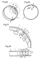
- the bottom 9 of the housing 2 has at its one transverse edge, the head 4 of the clamping screw 3 faces, on either side of the butt joint 11 each one of two radially outwardly bent tongues 14 which pass through together an opening 15 in the radially inner end portion 7 of Tension bands 1 protrude (Fig. 4 to 6). Furthermore, this towers Cross edge diagonally forward towards the clamping screw head 4 ( Figure 11). This will make the curved one Inside the end portion 7 during tightening the Clamp coming into contact under elevated line pressure Edge of the screw head 4 facing transverse edge in comparison to an exactly axial transverse edge slightly extended and, accordingly, their shearing action reduced to the tension band 1, so that the tension band. 1 withstand higher clamping forces without tearing.
- transverse edge 9a of the bottom 9 of the housing 12 is consistently straight and leaning on to this Transverse edge 9a towards open, radially inward from the Tension strap 1 pushed out beads 16 from.
- Tongues 14 common opening 15 on the side of the clamping screw head 4 adjoins an open to the bottom 9, in the radially inner end portion of the tension band. 1 trained bead 17, at which the rectilinear Transverse edge 9a opposite end of the bottom 9 in the side adjacent to the tongues 14 edge regions of the bottom 9 is supported.
- the inner end section 7 of the tension band 1 is free of a radially outward directed bend, as in known worm thread clamps provided for receiving the bottom 9 is.
- the beads 16, 17 extend in the circumferential direction the clamp, and the radially inner edge of each bead 16, 17 is aligned with the bottom of the bottom 9, wherein the edge steadily into the inside of the radially inner End section 7 passes. This results in marweit continuous transition between the housing bottom 9 and the inside of the tension band 1 with accordingly uniform clamping pressure distribution over the peripheral areas of a through the screw thread clamp clamped on a pipe, neck or the like Hose next to the bottom 9 of the housing. 2
- openings 18 prevent as well as the Opening 15, that the clamping band 1 when pushing out the Beading 16, 17 tears, if only transverse to the tape longitudinal direction running cuts formed in the tension band 1 would and the adjacent band areas for training the beads 16, 17 are pushed out.
- the housing 2 has only on his - at above the Tension bands 1 horizontal clamping screw 3 in the direction of Head 4 seen to the shaft 5 of the clamping screw 3 - right Side a lateral boom 19, the wall of radial outside the radially outer end portion 6 of the Tension band 1 next to the free end of the clamping screw shaft 5 one from a domed ridge 20 or top of the housing 2 tangential to a radial wall part 21 of the boom 19 sloping wall portion 22nd having. Furthermore, the boom next to a middle Section of the clamping screw shaft 5 a on this adjoining arched wall portion 23 and one arched Wall part 23 with the radial wall part 21 connecting axial wall part 24.
- the curved wall portion 23 and the axial wall portion 24th are by pressing the side wall of the housing. 2 educated. This leaves a transverse to the clamping screw. 3 extending wall portion 25 between the sloping Wall portion 22, the curved wall portion 23 and the axial wall part 24.
- the plane of the transverse wall portion 25 crosses approximately the middle of the with the tension band 1 in threaded engagement standing portion of the clamping screw.
- the surface pressure on the side of the most heavily loaded Transverse edge 9a of the housing bottom 9 lower and the connection to the housing bottom 9 and strap 1 with a higher clamping force in the circumferential direction of the clamping band. 1 Loadable without material deformation.
- the right in Fig. 4 Tongue 14 is more stressed during clamping than the adjacent one Tongue 14 and is therefore in the transverse direction wider than the left tongue 14 is formed.
- the boom 19 prevents a lateral tilting of the Housing 2 in a clockwise rotation of the clamping screw 3, while the worm thread clamp is tensioned, there the clamping screw 3 on the one hand endeavors, with its threaded shaft 5 on the upper side of the radially outer To unroll end section 6, and to the other by the oblique threaded elements 8 with an axial force component to the side in the direction of the boom 19 out is pressed.
- results from the sloping Wall portion 22 is a distance between one of the width of the Wall portion 22 in the length corresponding end portion the threaded shaft 5 of the clamping screw 3 and the housing wall, so that the thread the housing in the area of obliquely sloping wall portion 22 is not touched and therefore less subject to contact wear.
- the Clamping screw 3 is therefore also after repeated actuation and exerting a high clamping force over a easy to operate for a longer period of time.
- the lying on the side of the clamping screw head 4 end portion of the housing 2 is at its radially inner Edges provided with tabs 30 and 31, which after the Introduction of the clamping screw 3 in the housing 2 below the unthreaded neck of the clamping screw 3 are bent (Fig. 5, 6) and a return movement of the clamping screw 3 relative to the housing 2 when opening (relax) the Worm thread clamp by reverse rotation of the clamping screw 3 prevent.
- the head 4 of the clamping screw 3 facing free Edge of the upper part of the housing 2 is with teeth 32nd provided on which a radial surface of the head 4, here of the flange 27 of the head 4, is applied. If the Clamping force or the torque of the clamping screw 3 at Clamping exceeds a predetermined limit, the teeth 32 deform, so that their edges in the engage radial surface of the clamping screw head 4. Thereafter, the tension in the tension band 1 increases significantly less, even when trying to tighten or to increase the torque further, so that the danger a tear of the tape largely prevented becomes. Until reaching this predetermined clamping force, before the teeth 32 deform, the Clamping screw 3, however, relatively smooth and largely be turned freely.
- FIGS. 19 to 21 show in more detail the threaded elements 8 shown only schematically in FIGS. 5 to 7 and 8 and the thread of the clamping screw 3.
- the tension band 1 by tightening the clamping screw 3 contiguous flanks 33, 34 of the clamping band 3 embossed threaded elements 8 and the threaded ridge 35 of the clamping screw 3 at their outer and inner ends radii R 1 and R 2 .
- the steepness of these flanks 33, 34 corresponds to about 90 °.
- the remaining flanks 36 and 37 of the threaded elements 8 and the threaded ridge 35 have at their ends radii R 3 and R 4 , which are larger than the radii R 1 and R 2 .
- the radius R 3 at the free end of the flanks 36 of the threaded elements 8 is smaller than the radius R 4 at the foot of the flanks 36, while the radius R 3 at the free end of the flank 37 of the threaded ridge 35 is greater than the radius R 4 at the foot of the Flank 37 is.
- the radially inner side of the radially outer end portion 6 of the tension band 1 provided with the threaded elements 8 is largely planar.
- the thread ridges 38 between the impressed in the form of grooves threaded elements 8 have a bottom thickness d 1 in the range of 0.2 to 0.5 mm and a clamping band thickness d 2 in the range of 0.6 to 1 mm, a height h 1 in the range from 0.6 to 1 mm.
- the steepness of the flanks 32 and 34 corresponds approximately to a flank angle of 90 °, while the steepness of the flanks 36 and 37 corresponds to an angle ⁇ of about 15 °.
- This shape of the threaded elements 8 or thread ridges 38 in the radially outer end portion 6 of the clamping band 1 or the shape of the threaded ridge 35 of the clamping screw 3 has the following advantages:
- the steepness of the flanks 33 and 34 ensures that the threaded ridge 35 and the threaded elements 8 in contrast to oblique flanks, which are pressed together - even at very high clamping forces are not disengaged by higher additional radial force components.
- the small radii R 1 and R 2 result in radially longer, adjacent flanks than larger radii and consequently also lower radial force components during clamping, which endeavor to radially expand the thread of the clamping screw 3 and the threaded elements 8 of the clamping band 1.
- the relative to the radii R 1 and R 2 larger radii R 3 and R 4 result in a greater width of the thread ridges 38 at their free ends and at their foot, so that they are correspondingly higher loadable before they would deform.
- the small radius R 2 and the larger radius R 4 also have the advantage that the corresponding complementarily shaped, so far about trapezoidal or provided with a hipped top teeth of the die , through which the threaded elements 8 are embossed, have a longer service life, since the almost wedge-shaped teeth of the embossing punch can be more easily pressed into the material of the tension band 1.
- the largely flat radially inner side of the with Thread embossed end portion 6 of the clamping band 1 compared to a coinage, in which the radially inner side of the end portion 6 in almost the same Way like the radially outer side by use a corresponding lower embossing stamp when embossing is formed, has the advantage that between the embossed Section of the tension band and the means of Worm-threaded clamp clamped on a pipe socket Hose due to vibrations, in particular when using the worm thread clamp in motor vehicles, occurring friction is largely avoided.
- the embodiment according to FIG. 22 represents a slightly modified embossing compared with the embossing of the end section 6 of the tension band 1 shown in FIGS. 19 to 21.
- the radially inner side of the end section 6 is not flat but slightly wavy , and that to a large extent symmetrical, wherein the minimum of the corrugation coincide with those of the threaded elements 8 and the maxima of the corrugation with those of the threaded ledges 38 quasi synchronously.
- the dimensions depend in detail on the nominal diameter of the worm thread clamp or the hose to be clamped, the clamping band width and the clamping band material.
- the slight curl of the radially inner side of the end portion 6 of the tension band 1 is almost negligible in terms of friction, but has the advantage that the bottom thickness d 1 can be kept slightly larger than in the previous embodiment, because at the same height h 1 of the thread ridges 38th and the same strip thickness d 2 as in the previous embodiment, the free ends of the thread ridges 38 are higher, so that the thread elements 8 and webs 38 forming tool not penetrate so deep in the strip material and consequently the ground between the thread ridges 38 not so far needs to compact. This leads to a considerable increase in the service life of this embossing tool in comparison to the tool embossing the threaded elements 8 and thread rims 38 in the preceding embodiment.
Landscapes
- Engineering & Computer Science (AREA)
- General Engineering & Computer Science (AREA)
- Mechanical Engineering (AREA)
- Clamps And Clips (AREA)
Priority Applications (5)
| Application Number | Priority Date | Filing Date | Title |
|---|---|---|---|
| AU2003203218A AU2003203218B2 (en) | 2002-04-03 | 2003-03-27 | Worm Drive Hose Clip |
| RU2003109224/06A RU2258861C2 (ru) | 2002-04-03 | 2003-04-02 | Червячный резьбовой хомут |
| CA002424343A CA2424343C (fr) | 2002-04-03 | 2003-04-02 | Collier a serrage par vis sans fin |
| JP2003099142A JP4042609B2 (ja) | 2002-04-03 | 2003-04-02 | ウォーム駆動のホースクリップ |
| US10/405,838 US6845549B2 (en) | 2002-04-03 | 2003-04-02 | Worm drive hose clip |
Applications Claiming Priority (2)
| Application Number | Priority Date | Filing Date | Title |
|---|---|---|---|
| DE10214663 | 2002-04-03 | ||
| DE2002114663 DE10214663A1 (de) | 2002-04-03 | 2002-04-03 | Schneckengewindeschelle |
Publications (3)
| Publication Number | Publication Date |
|---|---|
| EP1351005A2 true EP1351005A2 (fr) | 2003-10-08 |
| EP1351005A3 EP1351005A3 (fr) | 2004-04-21 |
| EP1351005B1 EP1351005B1 (fr) | 2005-09-14 |
Family
ID=27816116
Family Applications (1)
| Application Number | Title | Priority Date | Filing Date |
|---|---|---|---|
| EP20020015824 Expired - Lifetime EP1351005B1 (fr) | 2002-04-03 | 2002-07-16 | Collier de serrage à vis tangente |
Country Status (3)
| Country | Link |
|---|---|
| EP (1) | EP1351005B1 (fr) |
| DE (2) | DE10214663A1 (fr) |
| ES (1) | ES2245390T3 (fr) |
Cited By (2)
| Publication number | Priority date | Publication date | Assignee | Title |
|---|---|---|---|---|
| EP2317199A1 (fr) * | 2009-10-28 | 2011-05-04 | NORMA Germany GmbH | Collier de serrage |
| EP2068064A3 (fr) * | 2007-12-04 | 2016-12-28 | NORMA Germany GmbH | Collier de serrage de moyeu d'entraînement |
Families Citing this family (1)
| Publication number | Priority date | Publication date | Assignee | Title |
|---|---|---|---|---|
| CN109595409B (zh) * | 2018-12-14 | 2020-12-11 | 徐州华显凯星信息科技有限公司 | 一种模具连接高压油管接头防爆防漏结构 |
Citations (1)
| Publication number | Priority date | Publication date | Assignee | Title |
|---|---|---|---|---|
| DE19633435C1 (de) | 1996-08-20 | 1998-02-12 | Rasmussen Gmbh | Schneckengewindeschelle |
Family Cites Families (4)
| Publication number | Priority date | Publication date | Assignee | Title |
|---|---|---|---|---|
| US3950830A (en) * | 1974-09-03 | 1976-04-20 | Standard-Thomson Corporation | Quick attachment and release worm gear type hose clamp |
| DE2854676C2 (de) * | 1978-12-18 | 1984-11-29 | Rasmussen Gmbh, 6457 Maintal | Schneckengewindeschelle |
| DE9419543U1 (de) * | 1994-12-06 | 1995-03-23 | GEMI Metallwarenfabrik GmbH & Co., 34431 Marsberg | Schlauchschelle |
| DE10026020B4 (de) * | 2000-05-25 | 2004-12-16 | Rasmussen Gmbh | Schneckengewindeschelle |
-
2002
- 2002-04-03 DE DE2002114663 patent/DE10214663A1/de not_active Withdrawn
- 2002-07-16 EP EP20020015824 patent/EP1351005B1/fr not_active Expired - Lifetime
- 2002-07-16 ES ES02015824T patent/ES2245390T3/es not_active Expired - Lifetime
- 2002-07-16 DE DE50204251T patent/DE50204251D1/de not_active Expired - Lifetime
Patent Citations (1)
| Publication number | Priority date | Publication date | Assignee | Title |
|---|---|---|---|---|
| DE19633435C1 (de) | 1996-08-20 | 1998-02-12 | Rasmussen Gmbh | Schneckengewindeschelle |
Cited By (4)
| Publication number | Priority date | Publication date | Assignee | Title |
|---|---|---|---|---|
| EP2068064A3 (fr) * | 2007-12-04 | 2016-12-28 | NORMA Germany GmbH | Collier de serrage de moyeu d'entraînement |
| EP2317199A1 (fr) * | 2009-10-28 | 2011-05-04 | NORMA Germany GmbH | Collier de serrage |
| CN102052533A (zh) * | 2009-10-28 | 2011-05-11 | 诺马德国有限责任公司 | 软管夹 |
| CN102052533B (zh) * | 2009-10-28 | 2014-03-05 | 诺马德国有限责任公司 | 软管夹 |
Also Published As
| Publication number | Publication date |
|---|---|
| EP1351005B1 (fr) | 2005-09-14 |
| ES2245390T3 (es) | 2006-01-01 |
| EP1351005A3 (fr) | 2004-04-21 |
| DE10214663A1 (de) | 2003-10-23 |
| DE50204251D1 (de) | 2005-10-20 |
Similar Documents
| Publication | Publication Date | Title |
|---|---|---|
| DE10026020B4 (de) | Schneckengewindeschelle | |
| DE4005631C2 (fr) | ||
| DE4342263C2 (de) | Großflächige Unterlegscheibe | |
| EP0599026B1 (fr) | Dispositif d'ancrage à cheville métallique expansible | |
| DE3017666C2 (fr) | ||
| EP0769648B1 (fr) | Collier de serrage | |
| DE3320681A1 (de) | Befestigungsschelle fuer schlauchleitung, verbindung und zugeordnetes verfahren | |
| DE2521684A1 (de) | Erschuetterungssicheres befestigungselement | |
| DE69217445T2 (de) | Klemmschelle | |
| CH677010A5 (fr) | ||
| DE2800824A1 (de) | Schneckengewindeschelle | |
| DE3122656C1 (de) | Schraublose Klemmschelle | |
| DE19750010C1 (de) | Schelle | |
| EP1351005B1 (fr) | Collier de serrage à vis tangente | |
| DE3127083A1 (de) | Nicht wiederverwendbare klemmschelle | |
| EP2987924A1 (fr) | Porte-butée pour coffrage mural | |
| EP1243838B1 (fr) | Collier de serrage | |
| DE19912324A1 (de) | Sanitärarmatur mit einer Mutter zur Befestigung | |
| DE19635677B4 (de) | Rohr- schlauch- oder sonstige schellenartige Verbindung | |
| EP1182368B1 (fr) | Dispositif de montage de pièces de fixation | |
| DE3942284C1 (fr) | ||
| EP1701046A1 (fr) | Cheville d'écartement | |
| EP1096160B1 (fr) | Dispositif de fixation | |
| EP0769646B1 (fr) | Collier de serrage | |
| DE19743121A1 (de) | Schellenanordnung zum Festklemmen eines Schlauches auf einem Rohrteil |
Legal Events
| Date | Code | Title | Description |
|---|---|---|---|
| PUAI | Public reference made under article 153(3) epc to a published international application that has entered the european phase |
Free format text: ORIGINAL CODE: 0009012 |
|
| AK | Designated contracting states |
Kind code of ref document: A2 Designated state(s): AT BE BG CH CY CZ DE DK EE ES FI FR GB GR IE IT LI LU MC NL PT SE SK TR |
|
| AX | Request for extension of the european patent |
Extension state: AL LT LV MK RO SI |
|
| PUAL | Search report despatched |
Free format text: ORIGINAL CODE: 0009013 |
|
| AK | Designated contracting states |
Kind code of ref document: A3 Designated state(s): AT BE BG CH CY CZ DE DK EE ES FI FR GB GR IE IT LI LU MC NL PT SE SK TR |
|
| AX | Request for extension of the european patent |
Extension state: AL LT LV MK RO SI |
|
| 17P | Request for examination filed |
Effective date: 20040318 |
|
| GRAP | Despatch of communication of intention to grant a patent |
Free format text: ORIGINAL CODE: EPIDOSNIGR1 |
|
| GRAS | Grant fee paid |
Free format text: ORIGINAL CODE: EPIDOSNIGR3 |
|
| AKX | Designation fees paid |
Designated state(s): DE ES FR GB IT |
|
| GRAA | (expected) grant |
Free format text: ORIGINAL CODE: 0009210 |
|
| AK | Designated contracting states |
Kind code of ref document: B1 Designated state(s): DE ES FR GB IT |
|
| REG | Reference to a national code |
Ref country code: GB Ref legal event code: FG4D Free format text: NOT ENGLISH |
|
| REF | Corresponds to: |
Ref document number: 50204251 Country of ref document: DE Date of ref document: 20051020 Kind code of ref document: P |
|
| GBT | Gb: translation of ep patent filed (gb section 77(6)(a)/1977) |
Effective date: 20051024 |
|
| REG | Reference to a national code |
Ref country code: ES Ref legal event code: FG2A Ref document number: 2245390 Country of ref document: ES Kind code of ref document: T3 |
|
| ET | Fr: translation filed | ||
| PLBE | No opposition filed within time limit |
Free format text: ORIGINAL CODE: 0009261 |
|
| STAA | Information on the status of an ep patent application or granted ep patent |
Free format text: STATUS: NO OPPOSITION FILED WITHIN TIME LIMIT |
|
| 26N | No opposition filed |
Effective date: 20060615 |
|
| REG | Reference to a national code |
Ref country code: DE Ref legal event code: R082 Ref document number: 50204251 Country of ref document: DE Representative=s name: PATENTANWAELTE OLBRICHT, BUCHHOLD, KEULERTZ PA, DE |
|
| REG | Reference to a national code |
Ref country code: FR Ref legal event code: PLFP Year of fee payment: 14 |
|
| REG | Reference to a national code |
Ref country code: FR Ref legal event code: PLFP Year of fee payment: 15 |
|
| REG | Reference to a national code |
Ref country code: FR Ref legal event code: PLFP Year of fee payment: 16 |
|
| REG | Reference to a national code |
Ref country code: FR Ref legal event code: PLFP Year of fee payment: 17 |
|
| PGFP | Annual fee paid to national office [announced via postgrant information from national office to epo] |
Ref country code: IT Payment date: 20210721 Year of fee payment: 20 Ref country code: FR Payment date: 20210726 Year of fee payment: 20 |
|
| PGFP | Annual fee paid to national office [announced via postgrant information from national office to epo] |
Ref country code: ES Payment date: 20210802 Year of fee payment: 20 Ref country code: GB Payment date: 20210727 Year of fee payment: 20 Ref country code: DE Payment date: 20210728 Year of fee payment: 20 |
|
| REG | Reference to a national code |
Ref country code: DE Ref legal event code: R071 Ref document number: 50204251 Country of ref document: DE |
|
| REG | Reference to a national code |
Ref country code: ES Ref legal event code: FD2A Effective date: 20220805 |
|
| REG | Reference to a national code |
Ref country code: GB Ref legal event code: PE20 Expiry date: 20220715 |
|
| PG25 | Lapsed in a contracting state [announced via postgrant information from national office to epo] |
Ref country code: GB Free format text: LAPSE BECAUSE OF EXPIRATION OF PROTECTION Effective date: 20220715 Ref country code: ES Free format text: LAPSE BECAUSE OF EXPIRATION OF PROTECTION Effective date: 20220717 |