EP2987924A1 - Porte-butée pour coffrage mural - Google Patents
Porte-butée pour coffrage mural Download PDFInfo
- Publication number
- EP2987924A1 EP2987924A1 EP15405049.6A EP15405049A EP2987924A1 EP 2987924 A1 EP2987924 A1 EP 2987924A1 EP 15405049 A EP15405049 A EP 15405049A EP 2987924 A1 EP2987924 A1 EP 2987924A1
- Authority
- EP
- European Patent Office
- Prior art keywords
- holder
- legs
- wedge element
- stopper
- wedge
- Prior art date
- Legal status (The legal status is an assumption and is not a legal conclusion. Google has not performed a legal analysis and makes no representation as to the accuracy of the status listed.)
- Granted
Links
Images


Classifications
-
- E—FIXED CONSTRUCTIONS
- E04—BUILDING
- E04G—SCAFFOLDING; FORMS; SHUTTERING; BUILDING IMPLEMENTS OR AIDS, OR THEIR USE; HANDLING BUILDING MATERIALS ON THE SITE; REPAIRING, BREAKING-UP OR OTHER WORK ON EXISTING BUILDINGS
- E04G17/00—Connecting or other auxiliary members for forms, falsework structures, or shutterings
- E04G17/06—Tying means; Spacers ; Devices for extracting or inserting wall ties
- E04G17/064—Spacers placed on the bottom of the mould
-
- E—FIXED CONSTRUCTIONS
- E04—BUILDING
- E04C—STRUCTURAL ELEMENTS; BUILDING MATERIALS
- E04C5/00—Reinforcing elements, e.g. for concrete; Auxiliary elements therefor
- E04C5/16—Auxiliary parts for reinforcements, e.g. connectors, spacers, stirrups
- E04C5/168—Spacers connecting parts for reinforcements and spacing the reinforcements from the form
Definitions
- the invention relates to a stop holder for a wall formwork according to the preamble of patent claim 1.
- Stop holders for wall formworks are known in many designs. They serve to define the exact distance between two formwork walls and thus determine the thickness of the wall to be concreted. Furthermore, they serve to adjust the distance to the protruding from a floor or ceiling plate connecting iron to the surface of the wall to be concreted.
- a distance and stop holder known in which a U-shaped metal profile, on both front sides indentations are mounted for inserting a spacer.
- a wedge is inserted between the connecting iron and the spacer.
- the indentations are formed on the metal profile at different distances to the base of the U-shaped metal profile.
- a disadvantage of this device is the one hand, the use of a construction unsuitable little wedge, which is lost and which is to keep bad in the other with the usually rough hands of construction workers.
- the stopper holder consists of three independent parts, which must be assembled in each case at the site.
- a stopper holder which is not attached to a connecting iron, but whose rod-shaped lower part must be inserted into the still soft concrete mass. After hardening of the concrete, the spacer attached to the upper part can be adjusted.
- the disadvantage of this stop holder is that only within a very specific period of time after concreting by hand, the stop holder must be set at the specified location. Is the concrete mass too fluid, the stopper holder can tip over; if it is already too hard, the latter can no longer be inserted.
- An object of the present invention is to provide a stopper holder which can be attached to terminal iron with different diameters undetachable and torsionally stable and which stop holder consists only of parts that are temporarily removable for transport, storage and provision on site can be put together and which stopper holder after attaching to the connecting iron already finds a secure hold on the connection iron and then definitely connectable to the connecting iron.
- two mutually cooperating elements namely a U-shaped holder and a likewise U-shaped wedge element which is slidable along an acute-angled contact surface in the holder to solve the above-described object.
- the two elements can be inexpensively made of flat material, such as steel, by a punching and bending process.
- at least one of the two parts could be made of a sufficiently stable other material, such as a plastic-based material.
- the stop holder comprises only two parts to be handled independently, and that these two parts can be temporarily inserted into each other to save space and captively.
- the wedge element By roughening or gearing or forming nubs on the edges of the wedge element and corresponding roughening, nubs, recesses or serrations on the inside of the sliding surface at the edges of the holder, the wedge element is held in the holder after attachment with a hammer on the reinforcing iron insoluble.
- the two legs on the wedge element are slightly conical to each other. In an advantageous embodiment, only the upper area of the two legs may be slightly bent outwards to allow a re-releasable, ie temporary clamping of the wedge element in the holder during transport.
- an acute angle ⁇ can be selected, which is greater than in the first embodiment of the invention and which in itself has no self-locking and still the connection between the sub-element and the holder is further improved.
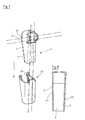
- the wedge element 1 has a U-shaped cross section with two legs 5 integrally formed on the base 3.
- the two free edges 7 of the legs 5 are the base 3 at an acute angle ⁇ (see. FIG. 3 ).
- the base 3 is in cross-section (see in FIG. 1a ) preferably W-shaped, that is, in the central region of the base 3, a V-shaped region 3a is formed, in which a connecting iron 9 (shown in broken lines) can rest centered (see FIG. FIG. 4 ).
- Recesses 11 may be formed in the V-shaped central region 3a, the edges of which may preferably have intentionally produced brews in the direction of the concave V-shaped region during punching.
- the regions of the legs 5 with the holes 15 are preferably not necessarily designed as tabs 13 projecting from the base body.
- the upper end of the two legs 5 has the shape of inwardly bent tabs 19, between the ends of a gap 21 has been generated by the width of a or their ends touching each other.
- the two inwardly bent tabs 19 form a striking surface on which the wedge element 1 can be hammered with a hammer or another impact tool into a holder 23 which rests on the surface of a concrete component 45 from which the reinforcing iron 9 protrudes.
- the base 3 of the wedge element 1 extends from the lower edge to below the tabs 13 at the upper region of the wedge element 1.
- the upper regions of the two legs 5 with the tabs 13 and the tabs 19 are preferably free-standing.
- the holder 23, as in the Figures 2 and 2a as well as the Figures 3 and 4 can be seen, comprises in cross-section a U-shaped profile with two holder legs 25, which are interconnected by a holder base 27.
- the free edge portions 29 of the two holder legs 25 are on the one hand bent at an angle of approximately 90 ° inwards, so that they face each other, and on the other hand, these extend at an acute angle ⁇ to the holder base 27.
- the holder base 27 is V-shaped in such a way that the interior of the V is directed against the two holder legs 25 and the contact area of the two V forming portions of the holder base 27 serves as a centering for the connecting iron 9.
- Holes or recesses 31 may be formed in the V-shaped portion of the holder base 27.
- the bent edge portions 29 on the legs 25 form on their inner sides, which are opposite to the holder base 27, a sliding surface 33 for the free edges 7 on the legs 5 of the wedge member 1 when inserted from above into the holder 23.
- the holder 23 therefore preferably comprises additional in the region of the lower edge Stabilizing agent (not shown).
- Such stabilizing means may in particular be deformed areas of the lower edge of the holder 23, which project outwardly and so effect a more effective support on the bottom or top plate of the concrete component 45, from which the connecting iron 9 protrudes.
- the two elements namely the holder 23 and the wedge element 1 are preferably made of steel, that is punched out of a steel sheet and formed in a stepped press by a bending process following the punching in the shape described.
- one or both of the elements may be made of a different material, e.g. Be made of plastic, if necessary, in conjunction with structural adjustments allows a sufficiently high stability and resilience of these elements.
- the described shape causes a stable in itself deformation-resistant shape, which makes it possible to exert high forces on a connecting iron 9, or by these high forces a stop bracket 35, consisting of the wedge element 1 and the holder 23, with the attached spacer 17 against rotation on Attaching iron 9 immovable.
- the legs 5 may be formed on the wedge element 1 tapered (see. FIG. 8 and FIG. 5a ).
- the conicity can, as in FIG. 8 shown over the entire length (height) of the wedge element 1 done or as out FIG. 5a visible, only over a partial length and / or also also perpendicular to the longitudinal axis of the wedge element 1 instead of only to the longitudinal axis.
- the two elements, wedge element 1 and holder 23, can be pulled apart again with little effort before assembly on a reinforcing iron and then placed over the reinforcing iron and be brought with the reinforcing iron by a hammer blow definitely in an immovable connection.
- the attachment of the stop holder 35, consisting of the wedge element 1 and the holder 23, takes place as described below.
- the holder 23 is applied in the radial direction to a connecting iron 9 and held with one hand.
- the wedge member 1 is inserted from above into the holder 23 together with the spacer 17, which is inserted on the wedge member 1.
- the wedge member 1 slides by its own weight along the sliding surfaces 33 and the base 3 parallel to the connecting iron 9 down and slightly wedged such that the stop bracket 35 is initially kept loose.
- After adjusting the guided transversely through the holes 15 on the tabs 13 spacers 17 is beaten vigorously with a hammer on the lobes 19 of the wedge member 1. This will be so further inserted and parallel to the connecting iron 9 in the holder 23.
- the wedge element 1 and the holder 23 are provided with additional roughenings or wedging elements such as sawteeth, Randr réelle or nubs, so there is a permanent locking of the wedge member 1 with the holder 23 when the wedge member 1 is hammered into the holder 23 with the hammer.
- the absolutely best latching takes place when the holder 25 rests on the concrete component 45. In this position, the adjustment of the spacer 35 in the horizontal direction is the easiest (no Fig.).
- connection iron 9 stop bracket 35 In FIG. 4 is fixed to the connection iron 9 stop bracket 35 in a fixed position at a distance from the concrete component 45 is shown. It is also apparent that the connecting iron 9 is exactly parallel to the base 28 of the holder 23 and simultaneously to the base 3 of the wedge element 1. At the same time the spacer 17 also comes into contact with the connecting iron 9. This contact prevents the spacer 17 axially in the wedge element 1 is displaceable.
Landscapes
- Engineering & Computer Science (AREA)
- Architecture (AREA)
- Mechanical Engineering (AREA)
- Civil Engineering (AREA)
- Structural Engineering (AREA)
- Forms Removed On Construction Sites Or Auxiliary Members Thereof (AREA)
- Clamps And Clips (AREA)
Applications Claiming Priority (2)
| Application Number | Priority Date | Filing Date | Title |
|---|---|---|---|
| CH01237/14A CH710002A2 (de) | 2014-08-18 | 2014-08-18 | Anschlaghalter für eine Wandschalung. |
| CH01597/14A CH710039A2 (de) | 2014-08-18 | 2014-10-18 | Anschlaghalter für eine Wandschalung. |
Publications (2)
| Publication Number | Publication Date |
|---|---|
| EP2987924A1 true EP2987924A1 (fr) | 2016-02-24 |
| EP2987924B1 EP2987924B1 (fr) | 2017-06-21 |
Family
ID=54196926
Family Applications (1)
| Application Number | Title | Priority Date | Filing Date |
|---|---|---|---|
| EP15405049.6A Active EP2987924B1 (fr) | 2014-08-18 | 2015-08-03 | Porte-butée pour coffrage mural |
Country Status (2)
| Country | Link |
|---|---|
| EP (1) | EP2987924B1 (fr) |
| CH (1) | CH710039A2 (fr) |
Cited By (3)
| Publication number | Priority date | Publication date | Assignee | Title |
|---|---|---|---|---|
| EP3029219A1 (fr) * | 2014-12-02 | 2016-06-08 | Pino Albanese | Procede de pose de dispositif d'entretoise, de butee ou d'ecarteur et entretoise, butee ou ecarteur |
| EP3358105A1 (fr) * | 2017-02-01 | 2018-08-08 | Pino Albanese | Procédé de raccordement d'un élément d'écartement à un fer de raccordement, à une cale, à un dispositif d'espacement et de pointage et à un support |
| EP3636848A1 (fr) * | 2018-09-27 | 2020-04-15 | Mägert Bautechnik AG | Élément de cale, entretoise dotée d'au moins un tel élément de cale, dispositif de positionnement doté d'une telle entretoise et procédé de positionnement de coffrage de mur |
Citations (4)
| Publication number | Priority date | Publication date | Assignee | Title |
|---|---|---|---|---|
| DE4439959A1 (de) * | 1994-03-09 | 1995-09-21 | Maegert Bautechnik Ag | Verfahren zum Setzen eines Anschlag- oder Distanzhalters |
| WO1997036070A1 (fr) * | 1996-03-22 | 1997-10-02 | Giulio Albanese | Porte-butee pour coffrage mural |
| DE10252296A1 (de) * | 2001-11-19 | 2003-07-17 | System Albanese Winterthur | Distanzhalterkeil |
| WO2014078969A1 (fr) * | 2012-11-22 | 2014-05-30 | Pino Albanese | Support de butée pour coffrages |
-
2014
- 2014-10-18 CH CH01597/14A patent/CH710039A2/de not_active Application Discontinuation
-
2015
- 2015-08-03 EP EP15405049.6A patent/EP2987924B1/fr active Active
Patent Citations (7)
| Publication number | Priority date | Publication date | Assignee | Title |
|---|---|---|---|---|
| DE4439959A1 (de) * | 1994-03-09 | 1995-09-21 | Maegert Bautechnik Ag | Verfahren zum Setzen eines Anschlag- oder Distanzhalters |
| CH687471A5 (de) | 1994-03-09 | 1996-12-13 | Maegert Bautechnik Ag | Verfahren zum Setzen eines Anschlag- oder Distanzhalters. |
| WO1997036070A1 (fr) * | 1996-03-22 | 1997-10-02 | Giulio Albanese | Porte-butee pour coffrage mural |
| EP0888486A1 (fr) | 1996-03-22 | 1999-01-07 | Giulio Albanese | Porte-butee pour coffrage mural |
| EP1197617A1 (fr) | 1996-03-22 | 2002-04-17 | Giulio Albanese | Dispositif pour fixer un élément distanceur |
| DE10252296A1 (de) * | 2001-11-19 | 2003-07-17 | System Albanese Winterthur | Distanzhalterkeil |
| WO2014078969A1 (fr) * | 2012-11-22 | 2014-05-30 | Pino Albanese | Support de butée pour coffrages |
Non-Patent Citations (1)
| Title |
|---|
| UWE KOERBITZ: "Klemmverbindung Konstruktionsbeispiel der verschiedenen Klemmungsarten", INTERNET, 26 October 2015 (2015-10-26), Internet, pages 1 - 6, XP055223534, Retrieved from the Internet <URL:http://www.konstruktionsatlas.de/verbindungstechnik/klemmverbindung/konstruktionsbeispiele.shtml> [retrieved on 20151026] * |
Cited By (4)
| Publication number | Priority date | Publication date | Assignee | Title |
|---|---|---|---|---|
| EP3029219A1 (fr) * | 2014-12-02 | 2016-06-08 | Pino Albanese | Procede de pose de dispositif d'entretoise, de butee ou d'ecarteur et entretoise, butee ou ecarteur |
| EP3358105A1 (fr) * | 2017-02-01 | 2018-08-08 | Pino Albanese | Procédé de raccordement d'un élément d'écartement à un fer de raccordement, à une cale, à un dispositif d'espacement et de pointage et à un support |
| EP3508667A1 (fr) | 2017-02-01 | 2019-07-10 | Pino Albanese | Procédé de raccordement d'un écarteur avec un fer de raccord, dispositif support d'écarteur et support de butée, cale et support |
| EP3636848A1 (fr) * | 2018-09-27 | 2020-04-15 | Mägert Bautechnik AG | Élément de cale, entretoise dotée d'au moins un tel élément de cale, dispositif de positionnement doté d'une telle entretoise et procédé de positionnement de coffrage de mur |
Also Published As
| Publication number | Publication date |
|---|---|
| CH710039A2 (de) | 2016-02-29 |
| EP2987924B1 (fr) | 2017-06-21 |
Similar Documents
| Publication | Publication Date | Title |
|---|---|---|
| DE19617750C1 (de) | Verankerungseinheit | |
| EP3708730B1 (fr) | Rails d'ancrage | |
| EP0671581A2 (fr) | Rail de montage pour la fixation de tuyaux ou similaires | |
| WO2016012081A1 (fr) | Dispositif de fixation d'un rail de montage | |
| EP2987924B1 (fr) | Porte-butée pour coffrage mural | |
| EP2910829B1 (fr) | Élément de collier de serrage de tuyau pour un support de tuyau et support de tuyau | |
| EP0554483B1 (fr) | Elément de liaison et de répartition des contraintes pour éléments de construction en béton | |
| EP3508667B1 (fr) | Procédé de raccordement d'un écarteur avec un fer de raccord, dispositif support d'écarteur et support de butée, cale et support | |
| EP3029219B1 (fr) | Procede de pose de dispositif d'entretoise, de butee ou d'ecarteur et entretoise, butee ou ecarteur | |
| CH695905A5 (de) | Abstand- und Distanzhalter. | |
| DE3333493A1 (de) | Selbstverspannender spreizanker | |
| CH710002A2 (de) | Anschlaghalter für eine Wandschalung. | |
| EP3636848B1 (fr) | Élément de cale, entretoise dotée d'au moins un tel élément de cale, dispositif de positionnement doté d'une telle entretoise et procédé de positionnement de coffrage de mur | |
| EP2977520B1 (fr) | Dispositif de positionnement selon un angle precis et une position precise et ancrage d'une barre de tension | |
| AT413723B (de) | Distanzhalterkeil | |
| EP2136027B1 (fr) | Raccordement d'angle pour cadre de porte et de fenêtre | |
| EP3663593B1 (fr) | Module comprenant un profilé creux et un module de raccordement ancré sur son côté avant | |
| CH714812B1 (de) | Erweiterungselement für einen Abschalwinkel. | |
| DE69002279T2 (de) | Rahmen. | |
| DE2004149C3 (de) | Schalungszuganker aus Bandstahl mit hohlem Aufsteckkonus | |
| DE29903131U1 (de) | Implantat zur Festlegung einer Knochenplatte | |
| DE19951913A1 (de) | Abstandhalter | |
| DE7419527U (de) | Anordnung zur Verbindung eines ersten stabförmigen Elements mit einem zweiten kreuzend daran vorbeigeführten stabförmigen Element | |
| DE102006008111A1 (de) | Halteelement für Gitter | |
| EP0057454A2 (fr) | Dispositif de suspension réglable en hauteur |
Legal Events
| Date | Code | Title | Description |
|---|---|---|---|
| PUAI | Public reference made under article 153(3) epc to a published international application that has entered the european phase |
Free format text: ORIGINAL CODE: 0009012 |
|
| AK | Designated contracting states |
Kind code of ref document: A1 Designated state(s): AL AT BE BG CH CY CZ DE DK EE ES FI FR GB GR HR HU IE IS IT LI LT LU LV MC MK MT NL NO PL PT RO RS SE SI SK SM TR |
|
| AX | Request for extension of the european patent |
Extension state: BA ME |
|
| 17P | Request for examination filed |
Effective date: 20160725 |
|
| RBV | Designated contracting states (corrected) |
Designated state(s): AL AT BE BG CH CY CZ DE DK EE ES FI FR GB GR HR HU IE IS IT LI LT LU LV MC MK MT NL NO PL PT RO RS SE SI SK SM TR |
|
| 17Q | First examination report despatched |
Effective date: 20160919 |
|
| STAA | Information on the status of an ep patent application or granted ep patent |
Free format text: STATUS: EXAMINATION IS IN PROGRESS |
|
| GRAP | Despatch of communication of intention to grant a patent |
Free format text: ORIGINAL CODE: EPIDOSNIGR1 |
|
| STAA | Information on the status of an ep patent application or granted ep patent |
Free format text: STATUS: GRANT OF PATENT IS INTENDED |
|
| INTG | Intention to grant announced |
Effective date: 20170118 |
|
| GRAS | Grant fee paid |
Free format text: ORIGINAL CODE: EPIDOSNIGR3 |
|
| GRAA | (expected) grant |
Free format text: ORIGINAL CODE: 0009210 |
|
| STAA | Information on the status of an ep patent application or granted ep patent |
Free format text: STATUS: THE PATENT HAS BEEN GRANTED |
|
| AK | Designated contracting states |
Kind code of ref document: B1 Designated state(s): AL AT BE BG CH CY CZ DE DK EE ES FI FR GB GR HR HU IE IS IT LI LT LU LV MC MK MT NL NO PL PT RO RS SE SI SK SM TR |
|
| REG | Reference to a national code |
Ref country code: GB Ref legal event code: FG4D Free format text: NOT ENGLISH |
|
| REG | Reference to a national code |
Ref country code: CH Ref legal event code: EP Ref country code: CH Ref legal event code: NV Representative=s name: GACHNANG AG PATENTANWAELTE, CH |
|
| REG | Reference to a national code |
Ref country code: IE Ref legal event code: FG4D Free format text: LANGUAGE OF EP DOCUMENT: GERMAN |
|
| REG | Reference to a national code |
Ref country code: AT Ref legal event code: REF Ref document number: 903078 Country of ref document: AT Kind code of ref document: T Effective date: 20170715 |
|
| REG | Reference to a national code |
Ref country code: DE Ref legal event code: R096 Ref document number: 502015001284 Country of ref document: DE |
|
| REG | Reference to a national code |
Ref country code: NL Ref legal event code: MP Effective date: 20170621 |
|
| PG25 | Lapsed in a contracting state [announced via postgrant information from national office to epo] |
Ref country code: LT Free format text: LAPSE BECAUSE OF FAILURE TO SUBMIT A TRANSLATION OF THE DESCRIPTION OR TO PAY THE FEE WITHIN THE PRESCRIBED TIME-LIMIT Effective date: 20170621 Ref country code: NO Free format text: LAPSE BECAUSE OF FAILURE TO SUBMIT A TRANSLATION OF THE DESCRIPTION OR TO PAY THE FEE WITHIN THE PRESCRIBED TIME-LIMIT Effective date: 20170921 Ref country code: HR Free format text: LAPSE BECAUSE OF FAILURE TO SUBMIT A TRANSLATION OF THE DESCRIPTION OR TO PAY THE FEE WITHIN THE PRESCRIBED TIME-LIMIT Effective date: 20170621 Ref country code: FI Free format text: LAPSE BECAUSE OF FAILURE TO SUBMIT A TRANSLATION OF THE DESCRIPTION OR TO PAY THE FEE WITHIN THE PRESCRIBED TIME-LIMIT Effective date: 20170621 Ref country code: GR Free format text: LAPSE BECAUSE OF FAILURE TO SUBMIT A TRANSLATION OF THE DESCRIPTION OR TO PAY THE FEE WITHIN THE PRESCRIBED TIME-LIMIT Effective date: 20170922 |
|
| REG | Reference to a national code |
Ref country code: LT Ref legal event code: MG4D |
|
| PG25 | Lapsed in a contracting state [announced via postgrant information from national office to epo] |
Ref country code: BG Free format text: LAPSE BECAUSE OF FAILURE TO SUBMIT A TRANSLATION OF THE DESCRIPTION OR TO PAY THE FEE WITHIN THE PRESCRIBED TIME-LIMIT Effective date: 20170921 Ref country code: LV Free format text: LAPSE BECAUSE OF FAILURE TO SUBMIT A TRANSLATION OF THE DESCRIPTION OR TO PAY THE FEE WITHIN THE PRESCRIBED TIME-LIMIT Effective date: 20170621 Ref country code: SE Free format text: LAPSE BECAUSE OF FAILURE TO SUBMIT A TRANSLATION OF THE DESCRIPTION OR TO PAY THE FEE WITHIN THE PRESCRIBED TIME-LIMIT Effective date: 20170621 Ref country code: RS Free format text: LAPSE BECAUSE OF FAILURE TO SUBMIT A TRANSLATION OF THE DESCRIPTION OR TO PAY THE FEE WITHIN THE PRESCRIBED TIME-LIMIT Effective date: 20170621 Ref country code: NL Free format text: LAPSE BECAUSE OF FAILURE TO SUBMIT A TRANSLATION OF THE DESCRIPTION OR TO PAY THE FEE WITHIN THE PRESCRIBED TIME-LIMIT Effective date: 20170621 |
|
| PG25 | Lapsed in a contracting state [announced via postgrant information from national office to epo] |
Ref country code: RO Free format text: LAPSE BECAUSE OF FAILURE TO SUBMIT A TRANSLATION OF THE DESCRIPTION OR TO PAY THE FEE WITHIN THE PRESCRIBED TIME-LIMIT Effective date: 20170621 Ref country code: EE Free format text: LAPSE BECAUSE OF FAILURE TO SUBMIT A TRANSLATION OF THE DESCRIPTION OR TO PAY THE FEE WITHIN THE PRESCRIBED TIME-LIMIT Effective date: 20170621 Ref country code: CZ Free format text: LAPSE BECAUSE OF FAILURE TO SUBMIT A TRANSLATION OF THE DESCRIPTION OR TO PAY THE FEE WITHIN THE PRESCRIBED TIME-LIMIT Effective date: 20170621 Ref country code: SK Free format text: LAPSE BECAUSE OF FAILURE TO SUBMIT A TRANSLATION OF THE DESCRIPTION OR TO PAY THE FEE WITHIN THE PRESCRIBED TIME-LIMIT Effective date: 20170621 |
|
| PG25 | Lapsed in a contracting state [announced via postgrant information from national office to epo] |
Ref country code: PL Free format text: LAPSE BECAUSE OF FAILURE TO SUBMIT A TRANSLATION OF THE DESCRIPTION OR TO PAY THE FEE WITHIN THE PRESCRIBED TIME-LIMIT Effective date: 20170621 Ref country code: IT Free format text: LAPSE BECAUSE OF FAILURE TO SUBMIT A TRANSLATION OF THE DESCRIPTION OR TO PAY THE FEE WITHIN THE PRESCRIBED TIME-LIMIT Effective date: 20170621 Ref country code: ES Free format text: LAPSE BECAUSE OF FAILURE TO SUBMIT A TRANSLATION OF THE DESCRIPTION OR TO PAY THE FEE WITHIN THE PRESCRIBED TIME-LIMIT Effective date: 20170621 Ref country code: SM Free format text: LAPSE BECAUSE OF FAILURE TO SUBMIT A TRANSLATION OF THE DESCRIPTION OR TO PAY THE FEE WITHIN THE PRESCRIBED TIME-LIMIT Effective date: 20170621 Ref country code: IS Free format text: LAPSE BECAUSE OF FAILURE TO SUBMIT A TRANSLATION OF THE DESCRIPTION OR TO PAY THE FEE WITHIN THE PRESCRIBED TIME-LIMIT Effective date: 20171021 |
|
| REG | Reference to a national code |
Ref country code: DE Ref legal event code: R097 Ref document number: 502015001284 Country of ref document: DE |
|
| PG25 | Lapsed in a contracting state [announced via postgrant information from national office to epo] |
Ref country code: MC Free format text: LAPSE BECAUSE OF FAILURE TO SUBMIT A TRANSLATION OF THE DESCRIPTION OR TO PAY THE FEE WITHIN THE PRESCRIBED TIME-LIMIT Effective date: 20170621 |
|
| PLBE | No opposition filed within time limit |
Free format text: ORIGINAL CODE: 0009261 |
|
| STAA | Information on the status of an ep patent application or granted ep patent |
Free format text: STATUS: NO OPPOSITION FILED WITHIN TIME LIMIT |
|
| PG25 | Lapsed in a contracting state [announced via postgrant information from national office to epo] |
Ref country code: DK Free format text: LAPSE BECAUSE OF FAILURE TO SUBMIT A TRANSLATION OF THE DESCRIPTION OR TO PAY THE FEE WITHIN THE PRESCRIBED TIME-LIMIT Effective date: 20170621 |
|
| REG | Reference to a national code |
Ref country code: BE Ref legal event code: MM Effective date: 20170831 |
|
| REG | Reference to a national code |
Ref country code: FR Ref legal event code: ST Effective date: 20180430 |
|
| 26N | No opposition filed |
Effective date: 20180322 |
|
| REG | Reference to a national code |
Ref country code: IE Ref legal event code: MM4A |
|
| PG25 | Lapsed in a contracting state [announced via postgrant information from national office to epo] |
Ref country code: LU Free format text: LAPSE BECAUSE OF NON-PAYMENT OF DUE FEES Effective date: 20170803 |
|
| PG25 | Lapsed in a contracting state [announced via postgrant information from national office to epo] |
Ref country code: IE Free format text: LAPSE BECAUSE OF NON-PAYMENT OF DUE FEES Effective date: 20170803 |
|
| PG25 | Lapsed in a contracting state [announced via postgrant information from national office to epo] |
Ref country code: BE Free format text: LAPSE BECAUSE OF NON-PAYMENT OF DUE FEES Effective date: 20170831 Ref country code: SI Free format text: LAPSE BECAUSE OF FAILURE TO SUBMIT A TRANSLATION OF THE DESCRIPTION OR TO PAY THE FEE WITHIN THE PRESCRIBED TIME-LIMIT Effective date: 20170621 Ref country code: FR Free format text: LAPSE BECAUSE OF NON-PAYMENT OF DUE FEES Effective date: 20170831 |
|
| PG25 | Lapsed in a contracting state [announced via postgrant information from national office to epo] |
Ref country code: MT Free format text: LAPSE BECAUSE OF FAILURE TO SUBMIT A TRANSLATION OF THE DESCRIPTION OR TO PAY THE FEE WITHIN THE PRESCRIBED TIME-LIMIT Effective date: 20170621 |
|
| PG25 | Lapsed in a contracting state [announced via postgrant information from national office to epo] |
Ref country code: HU Free format text: LAPSE BECAUSE OF FAILURE TO SUBMIT A TRANSLATION OF THE DESCRIPTION OR TO PAY THE FEE WITHIN THE PRESCRIBED TIME-LIMIT; INVALID AB INITIO Effective date: 20150803 |
|
| PG25 | Lapsed in a contracting state [announced via postgrant information from national office to epo] |
Ref country code: CY Free format text: LAPSE BECAUSE OF FAILURE TO SUBMIT A TRANSLATION OF THE DESCRIPTION OR TO PAY THE FEE WITHIN THE PRESCRIBED TIME-LIMIT Effective date: 20170621 |
|
| PG25 | Lapsed in a contracting state [announced via postgrant information from national office to epo] |
Ref country code: MK Free format text: LAPSE BECAUSE OF FAILURE TO SUBMIT A TRANSLATION OF THE DESCRIPTION OR TO PAY THE FEE WITHIN THE PRESCRIBED TIME-LIMIT Effective date: 20170621 |
|
| PG25 | Lapsed in a contracting state [announced via postgrant information from national office to epo] |
Ref country code: TR Free format text: LAPSE BECAUSE OF FAILURE TO SUBMIT A TRANSLATION OF THE DESCRIPTION OR TO PAY THE FEE WITHIN THE PRESCRIBED TIME-LIMIT Effective date: 20170621 |
|
| GBPC | Gb: european patent ceased through non-payment of renewal fee |
Effective date: 20190803 |
|
| PG25 | Lapsed in a contracting state [announced via postgrant information from national office to epo] |
Ref country code: PT Free format text: LAPSE BECAUSE OF FAILURE TO SUBMIT A TRANSLATION OF THE DESCRIPTION OR TO PAY THE FEE WITHIN THE PRESCRIBED TIME-LIMIT Effective date: 20170621 |
|
| PG25 | Lapsed in a contracting state [announced via postgrant information from national office to epo] |
Ref country code: AL Free format text: LAPSE BECAUSE OF FAILURE TO SUBMIT A TRANSLATION OF THE DESCRIPTION OR TO PAY THE FEE WITHIN THE PRESCRIBED TIME-LIMIT Effective date: 20170621 |
|
| PG25 | Lapsed in a contracting state [announced via postgrant information from national office to epo] |
Ref country code: GB Free format text: LAPSE BECAUSE OF NON-PAYMENT OF DUE FEES Effective date: 20190803 |
|
| REG | Reference to a national code |
Ref country code: AT Ref legal event code: MM01 Ref document number: 903078 Country of ref document: AT Kind code of ref document: T Effective date: 20200803 |
|
| PG25 | Lapsed in a contracting state [announced via postgrant information from national office to epo] |
Ref country code: AT Free format text: LAPSE BECAUSE OF NON-PAYMENT OF DUE FEES Effective date: 20200803 |
|
| REG | Reference to a national code |
Ref country code: CH Ref legal event code: PK Free format text: BERICHTIGUNGEN |
|
| PGFP | Annual fee paid to national office [announced via postgrant information from national office to epo] |
Ref country code: DE Payment date: 20250819 Year of fee payment: 11 |
|
| PGFP | Annual fee paid to national office [announced via postgrant information from national office to epo] |
Ref country code: CH Payment date: 20250901 Year of fee payment: 11 |