EP1351084A1 - Glasfaserkabel und sein Herstellungsprozess - Google Patents
Glasfaserkabel und sein Herstellungsprozess Download PDFInfo
- Publication number
- EP1351084A1 EP1351084A1 EP03290718A EP03290718A EP1351084A1 EP 1351084 A1 EP1351084 A1 EP 1351084A1 EP 03290718 A EP03290718 A EP 03290718A EP 03290718 A EP03290718 A EP 03290718A EP 1351084 A1 EP1351084 A1 EP 1351084A1
- Authority
- EP
- European Patent Office
- Prior art keywords
- frame
- cable
- optical fibers
- edges
- optical
- Prior art date
- Legal status (The legal status is an assumption and is not a legal conclusion. Google has not performed a legal analysis and makes no representation as to the accuracy of the status listed.)
- Withdrawn
Links
Images

Classifications
-
- G—PHYSICS
- G02—OPTICS
- G02B—OPTICAL ELEMENTS, SYSTEMS OR APPARATUS
- G02B6/00—Light guides; Structural details of arrangements comprising light guides and other optical elements, e.g. couplings
- G02B6/44—Mechanical structures for providing tensile strength and external protection for fibres, e.g. optical transmission cables
- G02B6/4401—Optical cables
- G02B6/4429—Means specially adapted for strengthening or protecting the cables
- G02B6/443—Protective covering
- G02B6/4431—Protective covering with provision in the protective covering, e.g. weak line, for gaining access to one or more fibres, e.g. for branching or tapping
Definitions
- the present invention relates to a fiber optic cable and a method of manufacture of this cable.
- Fiber optic cables hereinafter called optical cables, are susceptible to present structures of different types.
- a fiber optic cable of the type comprising a sheath, in which are housed optical fibers, and a substantially annular reinforcing reinforcement, interposed radially between the optical fibers and the sheath.
- the optical cable described in US-A-6 091 871 is of the type usually called "Uni-tube".
- This type of optical cable has a relatively small number of fibers optics.
- the optical fibers are housed in a single tube coated with the sheath.
- of the filiform elements forming traction reinforcements, usually called carriers, are embedded in a wall defining the sheath. The presence of carriers limits the possibilities of reduce the diameter of the sheath.
- the object of the invention is to propose an optical cable comprising a number relatively weak optical fibers (e.g. a dozen optical fibers) having as small a diameter as possible, usually keeping the characteristics desired for this type of cable, i.e. good resistance to crushing and traction and weak cold contraction.
- a number relatively weak optical fibers e.g. a dozen optical fibers
- the subject of the invention is a fiber optic cable of the aforementioned type, characterized in that the armature comprises a slot extending in the general longitudinal direction of the armature, this slot being delimited by edges of the frame separated or joined and allowing access to the optical fibers housed in the frame.
- the filling material prior to the extrusion of the sheath, the filling material is placed in the frame.
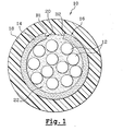
- FIG. 1 shows a fiber optic cable according to a first mode for carrying out the invention, designated by the general reference 10.
- the optical cable 10 comprises a bundle of conventional optical fibers 12. This bundle is housed in a substantially annular reinforcement frame 14. All reinforcement 14 - optical fibers 12 will hereinafter be called optical assembly 16.
- the optical assembly 16 is coated with a sheath 18.
- the frame 14 is therefore interposed radially between the optical fibers 12 and the sheath 18.
- the armature 14 is the only armature of the cable 10.
- the optical cable 10 comprises a relatively limited number of optical fibers 12, for example a dozen.
- the frame 14 is made of synthetic material reinforced, where appropriate, with fibers, in particular glass fibers, so as to limit the contraction of the optical cable 10 when cold.
- This synthetic material can in particular be of the type designated by the Anglo-Saxon acronym FRP (Fiber Reinforced Plastic) or GRP (Glass-fiber Reinforced Plastic).
- FRP Fiber Reinforced Plastic
- GRP Glass-fiber Reinforced Plastic
- the synthetic material can also be a material thermoplastic reinforced with glass fibers, especially in the form of wicks.
- the frame 14 can be made of metal, in particular steel, by example by rolling a steel sheet.
- the sheath 18 is made of a conventional synthetic material.
- This material classic is for example linear low density polyethylene usually designated by the Anglo-Saxon acronym LLDPE (Linear Low Density Polyethylene) or polyethylene to high density usually designated by the Anglo-Saxon acronym HDPE (High Density Polyethylene).
- LLDPE Linear Low Density Polyethylene
- HDPE High Density Polyethylene
- the armature 14 comprises a slot 20 extending in the direction longitudinal general of the frame 14. This slot 20 allows easy access to the fibers optics 12 housed in the frame 14.
- the slot 20 is delimited by edges B1, B2 of the frame 14 spaced a relatively small distance but greater than the diameter of an optical fiber 12.
- edges B1, B2 of the frame 14 delimiting the slot 20 are rectilinear.
- the edges B1, B2 of the frame 14 delimiting the slot 20 could extend along a path moving longitudinally in SZ.
- a filling material 22 is housed in the frame 14.
- This material in particular in the form of a gel or a powder, participates the sealing of the optical cable 10 and the protection of the optical fibers 12 during the extrusion of the sheath 18.
- the procedure is preferably as follows.
- the armature 14 is manufactured for example by extrusion if this frame 14 is made of synthetic material or else by bending a sheet metal if this frame 14 is metallic.
- the optical fibers 12 are housed in the frame 14 so as to form the optical assembly 16.
- the optical fibers 12 are introduced into the frame 14 through the slot 20.
- the filling material 22 is introduced into the reinforcement 14 before the extrusion of the sheath 18.
- the introduction of the filling material 22 in the frame 14 is done concomitantly with the introduction of the optical fibers 12 in this frame 14.
- the manufacture of the optical assembly 16 can be carried out in a installation separate from the installation in which the sheath 18 is extruded around the optical assembly 16. This authorizes the subcontracting of the manufacture of the optical assembly 16.
- the frame 14 gives the optical cable 10 good resistance to crushing and tensile and guarantees a low cold contraction of this optical cable 10.
- the step of extruding the sheath 18 around the optical assembly 16 can be carried out quickly and the thickness of the sheath 18 can be limited, which reduces correspondingly the external diameter of the optical cable 10.
- the frame 14 comprises two longitudinal half-frames 14A, 14B.
- Each half-frame 14A, 14B is provided with edges B1, B2 of contact with each other half-frame 14B, 14A.
- the contact edges B1, B2 of the two half-frames 14A, 14B form contiguous edges delimiting two slots 20 for access to the optical fibers 12.
- the edges B1, B2 of the frame 14 delimiting the two slots 20 are preferably rectilinear.
- the two half-frames 14A, 14B are held against each other using tearable or breakable means.
- These means include, for example, a link 24 wrapped around the frame 14 (covering).
- the link 24 can be threadlike or have a general form of ribbon.
- the link 24 is made for example from a material such as polyester, nylon ® or aramid.
- the user accesses the optical fibers 12 by cutting the sheath 18 at the right of the slot 20.
- the optical fibers 12 can be easily extracted from the armature 14 to through this slot 20.
- the user accesses the optical fibers 12 by cutting the sheath 18 and by cutting or by tearing the link 24 holding the two half-frames 14A, 14B against each other.
- the two half-frames 14A, 14B can then be separated from one another so as to open one of the slots 20 and give access to the optical fibers 12 housed in the frame 14.
- the invention therefore makes it possible to propose an optical cable, comprising a number relatively small optical fibers, having a reduced diameter, this preserving thanks to the reinforcing reinforcement 14 the characteristics usually desired for this type of cable, i.e. good crushing and tensile strength and low cold contraction.
- optical cable 10 consists of a number limited components and materials.
- the invention allows easy access to the optical fibers 12 of the cable. optical 10, even in the middle of the cable by incising the sheath 18.
- the optical fibers 12 can thus be connected by stitching the optical cable 10.
- the slot 20 is free, that is to say not blocked. Indeed, the slot 20 is not clogged with glue or solder.
Landscapes
- Physics & Mathematics (AREA)
- General Physics & Mathematics (AREA)
- Optics & Photonics (AREA)
- Light Guides In General And Applications Therefor (AREA)
- Mechanical Coupling Of Light Guides (AREA)
Applications Claiming Priority (2)
| Application Number | Priority Date | Filing Date | Title |
|---|---|---|---|
| FR0204085 | 2002-04-02 | ||
| FR0204085A FR2837932B1 (fr) | 2002-04-02 | 2002-04-02 | Cable a fibres optiques et procede de fabrication de ce cable |
Publications (1)
| Publication Number | Publication Date |
|---|---|
| EP1351084A1 true EP1351084A1 (de) | 2003-10-08 |
Family
ID=27839390
Family Applications (1)
| Application Number | Title | Priority Date | Filing Date |
|---|---|---|---|
| EP03290718A Withdrawn EP1351084A1 (de) | 2002-04-02 | 2003-03-21 | Glasfaserkabel und sein Herstellungsprozess |
Country Status (4)
| Country | Link |
|---|---|
| US (1) | US20030185528A1 (de) |
| EP (1) | EP1351084A1 (de) |
| CN (1) | CN1450376A (de) |
| FR (1) | FR2837932B1 (de) |
Families Citing this family (2)
| Publication number | Priority date | Publication date | Assignee | Title |
|---|---|---|---|---|
| US8548293B2 (en) * | 2008-05-28 | 2013-10-01 | Adc Telecommunications, Inc. | Fiber optic cable |
| FR2939911B1 (fr) * | 2008-12-12 | 2011-04-08 | Draka Comteq France | Fibre optique gainee, cable de telecommunication comportant plusieurs fibres optiques et procede de fabrication d'une telle fibre |
Citations (8)
| Publication number | Priority date | Publication date | Assignee | Title |
|---|---|---|---|---|
| CH422092A (de) * | 1964-02-03 | 1966-10-15 | Abegg & Co Ag Zuerich | Kabelschutzrohr aus Kunststoff |
| GB1574660A (en) * | 1977-12-05 | 1980-09-10 | Standard Telephones Cables Ltd | Optical communication cable |
| FR2555764A1 (fr) * | 1983-11-24 | 1985-05-31 | Nonclerq Bernard | Cable de transmission par fibre optique et procede de realisation de liaisons en faisant application |
| US4577925A (en) * | 1982-08-13 | 1986-03-25 | Olin Corporation | Optical fiber communication cables and method and apparatus for assembling same |
| JPS61233708A (ja) * | 1985-03-29 | 1986-10-18 | Fujikura Ltd | 光フアイバユニツト |
| US4647151A (en) * | 1983-10-29 | 1987-03-03 | International Standard Electric Corporation | Optical communication cable |
| WO1999053353A1 (de) * | 1998-04-15 | 1999-10-21 | Siemens Aktiengesellschaft | Optisches übertragungselement |
| EP1255144A2 (de) * | 2001-04-26 | 2002-11-06 | Fujikura Ltd. | Teilbares optisches Kabel |
Family Cites Families (2)
| Publication number | Priority date | Publication date | Assignee | Title |
|---|---|---|---|---|
| FR2756935B1 (fr) * | 1996-12-09 | 1999-01-08 | Alsthom Cge Alcatel | Cable a fibres optiques renforce, de structure unitube |
| US6744954B1 (en) * | 1998-11-20 | 2004-06-01 | Sumitomo Electric Industries, Ltd. | Submarine optical cable, optical fiber unit employed in the submarine optical cable, and method of making optical fiber unit |
-
2002
- 2002-04-02 FR FR0204085A patent/FR2837932B1/fr not_active Expired - Fee Related
-
2003
- 2003-03-21 EP EP03290718A patent/EP1351084A1/de not_active Withdrawn
- 2003-03-27 US US10/397,203 patent/US20030185528A1/en not_active Abandoned
- 2003-04-01 CN CN03121594.7A patent/CN1450376A/zh active Pending
Patent Citations (8)
| Publication number | Priority date | Publication date | Assignee | Title |
|---|---|---|---|---|
| CH422092A (de) * | 1964-02-03 | 1966-10-15 | Abegg & Co Ag Zuerich | Kabelschutzrohr aus Kunststoff |
| GB1574660A (en) * | 1977-12-05 | 1980-09-10 | Standard Telephones Cables Ltd | Optical communication cable |
| US4577925A (en) * | 1982-08-13 | 1986-03-25 | Olin Corporation | Optical fiber communication cables and method and apparatus for assembling same |
| US4647151A (en) * | 1983-10-29 | 1987-03-03 | International Standard Electric Corporation | Optical communication cable |
| FR2555764A1 (fr) * | 1983-11-24 | 1985-05-31 | Nonclerq Bernard | Cable de transmission par fibre optique et procede de realisation de liaisons en faisant application |
| JPS61233708A (ja) * | 1985-03-29 | 1986-10-18 | Fujikura Ltd | 光フアイバユニツト |
| WO1999053353A1 (de) * | 1998-04-15 | 1999-10-21 | Siemens Aktiengesellschaft | Optisches übertragungselement |
| EP1255144A2 (de) * | 2001-04-26 | 2002-11-06 | Fujikura Ltd. | Teilbares optisches Kabel |
Non-Patent Citations (2)
| Title |
|---|
| "BEND PROTECTION FOR FIBRE OPTIC CABLE", RESEARCH DISCLOSURE, KENNETH MASON PUBLICATIONS, HAMPSHIRE, GB, no. 417, January 1999 (1999-01-01), pages 63, XP000888432, ISSN: 0374-4353 * |
| PATENT ABSTRACTS OF JAPAN vol. 011, no. 072 (P - 554) 5 March 1987 (1987-03-05) * |
Also Published As
| Publication number | Publication date |
|---|---|
| CN1450376A (zh) | 2003-10-22 |
| FR2837932B1 (fr) | 2004-11-05 |
| FR2837932A1 (fr) | 2003-10-03 |
| US20030185528A1 (en) | 2003-10-02 |
Similar Documents
| Publication | Publication Date | Title |
|---|---|---|
| EP0846971B1 (de) | Verstärktes faseroptisches Kabel mit einer Einrohrstruktur | |
| FR2915002A1 (fr) | Procede d'acces a une ou plusieurs fibres optiques d'un cable de telecommunication | |
| FR2904876A1 (fr) | Cable de telecommunication a fibres optiques | |
| EP1463904B2 (de) | Durch überlappen wiederverschliessbare schutzhülle und verwendung davon | |
| FR2593929A1 (fr) | Cable a fibres optiques | |
| FR2757642A1 (fr) | Cable a fibres optiques a structure dissymetrique | |
| CA1096215A (fr) | Cable optique de telecommunication | |
| EP0720034A1 (de) | Optisches Kabel und Verfahren zu seiner Fabrikation | |
| BE898104R (fr) | Cable à fibres optiques. | |
| EP0872749B1 (de) | Verfahren zur Herstellung eines Lichtwellenleiterkabels | |
| FR2793565A1 (fr) | Cable a fibres optiques ayant des renforts longitudinaux reperes | |
| FR2829841A1 (fr) | Cable a forte densite de fibres optiques | |
| EP1351084A1 (de) | Glasfaserkabel und sein Herstellungsprozess | |
| EP0364317A1 (de) | Optisches Kabel | |
| EP0790511A1 (de) | Faseroptisches Kabel ohne Verstärkungselement | |
| FR2652572A1 (fr) | Procede d'enroulement en double d'un cable ou analogue sur la surface externe d'un touret. | |
| EP0311941B1 (de) | Fabrikationsverfahren für ein optisches Kabel und danach hergestelltes Kabel | |
| EP1220000B1 (de) | Faseroptisches Kabel und zugehöriges Herstellungsverfahren | |
| US9316802B2 (en) | Optical fiber cable having reinforcing layer of tape heat-bonded to jacket | |
| FR2505057A1 (fr) | Element porteur non metallique pour cable et cable comportant un tel porteur | |
| FR2489002A1 (fr) | Noyau de cable de telecommunication a fibres optiques | |
| EP0165471A1 (de) | Zugfeste Bewehrung für Kabel und Kabel zur Anwendung unter Wasser mit einer ähnlichen Bewehrung versehen | |
| EP0724105B1 (de) | Rohranordnung für ein Kraftfahrzeug | |
| FR2501871A1 (fr) | Element de cable a fibres optiques comportant un element porteur et dispositif destine a sa fabrication | |
| EP2548710B1 (de) | Herstellungsverfahren eines mikrorohrs |
Legal Events
| Date | Code | Title | Description |
|---|---|---|---|
| PUAI | Public reference made under article 153(3) epc to a published international application that has entered the european phase |
Free format text: ORIGINAL CODE: 0009012 |
|
| AK | Designated contracting states |
Kind code of ref document: A1 Designated state(s): AT BE BG CH CY CZ DE DK EE ES FI FR GB GR HU IE IT LI LU MC NL PT RO SE SI SK TR |
|
| AX | Request for extension of the european patent |
Extension state: AL LT LV MK |
|
| 17P | Request for examination filed |
Effective date: 20040408 |
|
| AKX | Designation fees paid |
Designated state(s): AT BE BG CH CY CZ DE DK EE ES FI FR GB GR HU IE IT LI LU MC NL PT RO SE SI SK TR |
|
| STAA | Information on the status of an ep patent application or granted ep patent |
Free format text: STATUS: THE APPLICATION HAS BEEN WITHDRAWN |
|
| 18W | Application withdrawn |
Effective date: 20050221 |