US20030185528A1 - Optical fiber cable and a method of fabricating it - Google Patents
Optical fiber cable and a method of fabricating it Download PDFInfo
- Publication number
- US20030185528A1 US20030185528A1 US10/397,203 US39720303A US2003185528A1 US 20030185528 A1 US20030185528 A1 US 20030185528A1 US 39720303 A US39720303 A US 39720303A US 2003185528 A1 US2003185528 A1 US 2003185528A1
- Authority
- US
- United States
- Prior art keywords
- strength member
- cable
- optical
- sheath
- edges
- Prior art date
- Legal status (The legal status is an assumption and is not a legal conclusion. Google has not performed a legal analysis and makes no representation as to the accuracy of the status listed.)
- Abandoned
Links
- 239000013307 optical fiber Substances 0.000 title claims abstract description 51
- 238000004519 manufacturing process Methods 0.000 title claims description 5
- 230000003287 optical effect Effects 0.000 claims description 36
- 239000000463 material Substances 0.000 claims description 14
- 229920002994 synthetic fiber Polymers 0.000 claims description 13
- 229920002430 Fibre-reinforced plastic Polymers 0.000 claims description 6
- 239000011151 fibre-reinforced plastic Substances 0.000 claims description 6
- 239000011152 fibreglass Substances 0.000 claims description 6
- 239000000945 filler Substances 0.000 claims description 6
- 239000000835 fiber Substances 0.000 claims description 5
- 239000003365 glass fiber Substances 0.000 claims description 5
- 239000002184 metal Substances 0.000 claims description 5
- 229910000831 Steel Inorganic materials 0.000 claims description 4
- 239000010959 steel Substances 0.000 claims description 4
- 239000000843 powder Substances 0.000 claims description 3
- 229920001169 thermoplastic Polymers 0.000 claims description 3
- 239000004416 thermosoftening plastic Substances 0.000 claims description 3
- 238000000034 method Methods 0.000 claims 1
- 230000008602 contraction Effects 0.000 description 4
- 238000005520 cutting process Methods 0.000 description 4
- 239000004700 high-density polyethylene Substances 0.000 description 2
- 238000009434 installation Methods 0.000 description 2
- 241000531908 Aramides Species 0.000 description 1
- 229920010126 Linear Low Density Polyethylene (LLDPE) Polymers 0.000 description 1
- 239000000853 adhesive Substances 0.000 description 1
- 230000001070 adhesive effect Effects 0.000 description 1
- 229920003235 aromatic polyamide Polymers 0.000 description 1
- 238000005452 bending Methods 0.000 description 1
- 238000001125 extrusion Methods 0.000 description 1
- 229920001903 high density polyethylene Polymers 0.000 description 1
- 238000003780 insertion Methods 0.000 description 1
- 230000037431 insertion Effects 0.000 description 1
- 229920004889 linear high-density polyethylene Polymers 0.000 description 1
- 229920001778 nylon Polymers 0.000 description 1
- 229920000728 polyester Polymers 0.000 description 1
- 238000005096 rolling process Methods 0.000 description 1
- 238000007789 sealing Methods 0.000 description 1
- 238000005728 strengthening Methods 0.000 description 1
- 238000003466 welding Methods 0.000 description 1
Images


Classifications
-
- G—PHYSICS
- G02—OPTICS
- G02B—OPTICAL ELEMENTS, SYSTEMS OR APPARATUS
- G02B6/00—Light guides; Structural details of arrangements comprising light guides and other optical elements, e.g. couplings
- G02B6/44—Mechanical structures for providing tensile strength and external protection for fibres, e.g. optical transmission cables
- G02B6/4401—Optical cables
- G02B6/4429—Means specially adapted for strengthening or protecting the cables
-
- G—PHYSICS
- G02—OPTICS
- G02B—OPTICAL ELEMENTS, SYSTEMS OR APPARATUS
- G02B6/00—Light guides; Structural details of arrangements comprising light guides and other optical elements, e.g. couplings
- G02B6/44—Mechanical structures for providing tensile strength and external protection for fibres, e.g. optical transmission cables
- G02B6/4401—Optical cables
- G02B6/4429—Means specially adapted for strengthening or protecting the cables
- G02B6/443—Protective covering
- G02B6/4431—Protective covering with provision in the protective covering, e.g. weak line, for gaining access to one or more fibres, e.g. for branching or tapping
Definitions
- the present invention relates to an optical fiber cable and a method of fabricating it.
- Optical fiber cables can have structures of different types.
- U.S. Pat. No. 6,091,871 describes a prior art optical fiber cable comprising a sheath accommodating optical fibers and a substantially annular strength member interleaved radially between the optical fibers and the sheath.
- the optical cable described in U.S. Pat. No. 6,091,871 is a uni-tube cable.
- This type of optical cable contains a relatively small number of optical fibers housed in a single tube covered with the sheath.
- Filamentary members providing strengthening in traction usually referred to as strength members, are buried in a wall delimiting the sheath. The presence of the strength members limits the possibilities of reducing the diameter of the sheath.
- An object of the invention is to propose an optical cable containing a relatively small number of optical fibers (for example about twelve optical fibers) and having as small a diameter as possible, whilst retaining the features usually required of this type of cable, namely good resistance to crushing and traction and low contraction at low temperatures.
- the invention provides an optical fiber cable including a sheath, optical fibers accommodated in the sheath, and a substantially annular strength member radially between the optical fibers and the sheath, which strength member has a slot extending in its general longitudinal direction, delimited by separated or contiguous edges of the strength member, and providing access to the optical fibers accommodated in the strength member.
- optical cable [0010] Different embodiments of the optical cable have the following features:
- edges of the strength member delimiting the access slot are separated by a distance greater than the diameter of an optical fiber
- the strength member comprises two longitudinal half-members each of which has edges in contact with the other half-member, the edges in contact of the half-members forming contiguous edges delimiting two optical fiber access slots;
- the optical cable includes means for holding the two half-members together and adapted to be torn or cut;
- the means for holding the two half-members together comprise a tie wrapped around the strength member
- the strength member is made from a synthetic material
- the synthetic material of the strength member is reinforced with fibers, for example glass fibers, and the synthetic material is a material known as fiber reinforced plastic (FRP) or glassfiber reinforced plastic (GRP);
- FRP fiber reinforced plastic
- GRP glassfiber reinforced plastic
- the synthetic material of the strength member is a thermoplastics material
- the strength member is made of metal, for example steel
- the edges of the strength member delimiting the access slot have an SZ shape
- a filler material for example a gel or a powder, is accommodated in the strength member.
- the invention also provides a method of fabricating an optical cable as defined above, wherein:
- the strength member is fabricated
- the optical fibers are accommodated in the strength member to form an optical assembly comprising the strength member and the optical fibers, and
- the sheath is extruded around the optical assembly.
- the filler material is placed in the strength member before extruding the sheath.
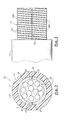
- FIG. 1 is a view in cross section of a first embodiment of an optical fiber cable according to the invention.
- FIG. 2 is a view similar to FIG. 1 of a second embodiment of an optical fiber cable according to the invention.
- FIG. 3 is a side view of the optical cable shown in FIG. 2.
- FIG. 1 shows a first embodiment of an optical fiber cable according to the invention.
- the optical cable 10 includes a bundle of conventional optical fibers 12 accommodated in a substantially annular strength member 14 .
- the assembly comprising the strength member 14 and the optical fibers 12 is referred to hereinafter as an optical assembly 16 .
- the optical assembly 16 is covered with a sheath 18 .
- the strength member 14 is therefore radially between the optical fibers 12 and the sheath 18 .
- the strength member 14 is preferably the only strength member of the cable 10 .
- the optical cable 10 includes a relatively small number of optical fibers 12 , for example about twelve fibers.
- the strength member 14 is made from a synthetic material, if necessary reinforced with fibers, in particular glass fibers, to limit contraction of the optical cable 10 at low temperatures.
- the synthetic material can be a material known as fiber-reinforced plastic (FRP) or a material known as glassfiber-reinforced plastic (GRP).
- FRP fiber-reinforced plastic
- GRP glassfiber-reinforced plastic
- the synthetic material can equally well be a thermoplastics material reinforced with glass fibers, in particular in the form of wicks.
- the strength member 14 can be made of metal, in particular of steel, for example by rolling sheet steel.
- the sheath 18 is made from a conventional synthetic material, for example linear low density polyethylene (LLDPE) or high density polyethylene (HDPE).
- LLDPE linear low density polyethylene
- HDPE high density polyethylene
- the strength member 14 has a slot 20 extending in its general longitudinal direction.
- the slot 20 provides easy access to the optical fibers 12 accommodated in the strength member 14 .
- the slot 20 is delimited by edges B 1 , B 2 of the strength member 14 , the distance between which is relatively small but greater than the diameter of an optical fiber 12 .
- edges B 1 , B 2 of the strength member 14 delimiting the slot 20 are straight.
- the edges B 1 , B 2 of the strength member 14 delimiting the slot 20 could have the SZ (complex spiral) shape known in the art.
- the strength member 14 preferably accommodates conventional filler material 22 , for example a gel or a powder, which contributes to sealing the optical cable 10 and to protecting the optical fibers 12 when the sheath 18 is extruded.
- conventional filler material 22 for example a gel or a powder
- the optical cable 10 is preferably fabricated in the following manner.
- the strength member 14 is fabricated, for example by extrusion if the strength member 14 is made of a synthetic material or by bending sheet metal if the strength member 14 is made of metal.
- the optical fibers 12 are inserted into the strength member 14 to form the optical assembly 16 , through the slot 20 .
- the filler material 22 is introduced into the strength member 14 before extruding the sheath 18 , and preferably concomitantly with the insertion of the optical fibers 12 into the strength member 14 .
- the optical assembly 16 can be fabricated on an installation separate from the installation in which the sheath 18 is extruded around the optical assembly 16 . This enables fabrication of the optical assembly 16 to be subcontracted.
- the strength member 14 confers on the optical cable 10 good resistance to crushing and traction and guarantees little contraction of the optical cable 10 at low temperatures.
- the sheath 18 can be extruded around the optical assembly 16 quickly and the thickness of the sheath 18 can be limited, which reduces commensurately the outside diameter of the optical cable 10 .
- FIGS. 2 and 3 show a second embodiment of an optical cable according to the invention.
- components analogous to those in FIG. 1 are designated by the same reference number.
- the strength member 14 comprises two longitudinal half-members 14 A, 14 B.
- Each half-member 14 A, 14 B has edges B 1 , B 2 in contact with the other half-member 14 B, 14 A.
- the contacting edges B 1 , B 2 of the two half-members 14 A, 14 B form contiguous edges delimiting two slots 20 providing access to the optical fibers 12 .
- the edges B 1 , B 2 of the strength member 14 delimiting the two slots 20 are preferably straight.
- the two half-members 14 A, 14 B are held together by means that can be torn or cut, for example a tie 24 wrapped around the strength member 14 (this is known as binding).
- the tie 24 can be a filament or a tape and is fabricated from polyester, Nylon® or aramide, for example.
- One advantage of the invention is that it provides easy access to the optical fibers 12 of the optical cable 10 and thus easy connection of the optical fibers 12 .
- the user obtains access to the optical fibers 12 by cutting the sheath 18 in line with the slot 20 .
- the optical fibers 12 can be easily extracted from the strength member 14 through the slot 20 .
- the user obtains access to the optical fibers 12 by cutting the sheath 18 and cutting or tearing the tie 24 holding the two half-members 14 A, 14 B together.
- the two half-members 14 A, 14 B can then be spread apart to open one of the slots 20 and provide access to the optical fibers 12 accommodated in the strength member 14 .
- the invention therefore proposes an optical cable including a relatively small number of optical fibers and having a small diameter but, thanks to the strength member 14 , retaining the features usually required of this type of cable, namely good resistance to crushing and traction and low contraction at low temperatures.
- optical cable 10 is made from a limited number of components and materials.
- the invention provides easy access to the optical fibers 12 of the optical cable 10 by cutting the sheath 18 , even in the middle of the cable.
- the optical fibers 12 can therefore be connected partway along the optical cable 10 .
- the slot 20 is open, i.e. not stopped up by adhesive or welding.
Landscapes
- Physics & Mathematics (AREA)
- General Physics & Mathematics (AREA)
- Optics & Photonics (AREA)
- Light Guides In General And Applications Therefor (AREA)
- Mechanical Coupling Of Light Guides (AREA)
Applications Claiming Priority (2)
| Application Number | Priority Date | Filing Date | Title |
|---|---|---|---|
| FR0204085 | 2002-04-02 | ||
| FR0204085A FR2837932B1 (fr) | 2002-04-02 | 2002-04-02 | Cable a fibres optiques et procede de fabrication de ce cable |
Publications (1)
| Publication Number | Publication Date |
|---|---|
| US20030185528A1 true US20030185528A1 (en) | 2003-10-02 |
Family
ID=27839390
Family Applications (1)
| Application Number | Title | Priority Date | Filing Date |
|---|---|---|---|
| US10/397,203 Abandoned US20030185528A1 (en) | 2002-04-02 | 2003-03-27 | Optical fiber cable and a method of fabricating it |
Country Status (4)
| Country | Link |
|---|---|
| US (1) | US20030185528A1 (de) |
| EP (1) | EP1351084A1 (de) |
| CN (1) | CN1450376A (de) |
| FR (1) | FR2837932B1 (de) |
Cited By (2)
| Publication number | Priority date | Publication date | Assignee | Title |
|---|---|---|---|---|
| US20100150505A1 (en) * | 2008-12-12 | 2010-06-17 | Draka Comteq, B.V. | Buffered Optical Fiber |
| US11409065B2 (en) * | 2008-05-28 | 2022-08-09 | Commscope Technologies Llc | Fiber optic cable |
Citations (4)
| Publication number | Priority date | Publication date | Assignee | Title |
|---|---|---|---|---|
| US4577925A (en) * | 1982-08-13 | 1986-03-25 | Olin Corporation | Optical fiber communication cables and method and apparatus for assembling same |
| US4647151A (en) * | 1983-10-29 | 1987-03-03 | International Standard Electric Corporation | Optical communication cable |
| US6091871A (en) * | 1996-12-09 | 2000-07-18 | Alcatel | Reinforced optical fiber cable of unitube structure |
| US6744954B1 (en) * | 1998-11-20 | 2004-06-01 | Sumitomo Electric Industries, Ltd. | Submarine optical cable, optical fiber unit employed in the submarine optical cable, and method of making optical fiber unit |
Family Cites Families (6)
| Publication number | Priority date | Publication date | Assignee | Title |
|---|---|---|---|---|
| CH422092A (de) * | 1964-02-03 | 1966-10-15 | Abegg & Co Ag Zuerich | Kabelschutzrohr aus Kunststoff |
| GB1574660A (en) * | 1977-12-05 | 1980-09-10 | Standard Telephones Cables Ltd | Optical communication cable |
| FR2555764B1 (fr) * | 1983-11-24 | 1986-10-10 | Nonclerq Bernard | Cable de transmission par fibre optique et procede de realisation de liaisons en faisant application |
| JPS61233708A (ja) * | 1985-03-29 | 1986-10-18 | Fujikura Ltd | 光フアイバユニツト |
| EP1093594A1 (de) * | 1998-04-15 | 2001-04-25 | Siemens Aktiengesellschaft | Optisches übertragungselement |
| JP2002328277A (ja) * | 2001-04-26 | 2002-11-15 | Fujikura Ltd | 光ケーブル |
-
2002
- 2002-04-02 FR FR0204085A patent/FR2837932B1/fr not_active Expired - Fee Related
-
2003
- 2003-03-21 EP EP03290718A patent/EP1351084A1/de not_active Withdrawn
- 2003-03-27 US US10/397,203 patent/US20030185528A1/en not_active Abandoned
- 2003-04-01 CN CN03121594.7A patent/CN1450376A/zh active Pending
Patent Citations (4)
| Publication number | Priority date | Publication date | Assignee | Title |
|---|---|---|---|---|
| US4577925A (en) * | 1982-08-13 | 1986-03-25 | Olin Corporation | Optical fiber communication cables and method and apparatus for assembling same |
| US4647151A (en) * | 1983-10-29 | 1987-03-03 | International Standard Electric Corporation | Optical communication cable |
| US6091871A (en) * | 1996-12-09 | 2000-07-18 | Alcatel | Reinforced optical fiber cable of unitube structure |
| US6744954B1 (en) * | 1998-11-20 | 2004-06-01 | Sumitomo Electric Industries, Ltd. | Submarine optical cable, optical fiber unit employed in the submarine optical cable, and method of making optical fiber unit |
Cited By (3)
| Publication number | Priority date | Publication date | Assignee | Title |
|---|---|---|---|---|
| US11409065B2 (en) * | 2008-05-28 | 2022-08-09 | Commscope Technologies Llc | Fiber optic cable |
| US20100150505A1 (en) * | 2008-12-12 | 2010-06-17 | Draka Comteq, B.V. | Buffered Optical Fiber |
| US8346040B2 (en) * | 2008-12-12 | 2013-01-01 | Draka Comteq, B.V. | Buffered optical fiber |
Also Published As
| Publication number | Publication date |
|---|---|
| EP1351084A1 (de) | 2003-10-08 |
| FR2837932A1 (fr) | 2003-10-03 |
| CN1450376A (zh) | 2003-10-22 |
| FR2837932B1 (fr) | 2004-11-05 |
Similar Documents
| Publication | Publication Date | Title |
|---|---|---|
| CN100480761C (zh) | 具有接纳光纤的护套管道的光缆 | |
| US6256438B1 (en) | Fiber optic drop cable | |
| JP4547367B2 (ja) | 光ファイバ配線ケーブルの製造方法 | |
| AU2001275704B2 (en) | Optical fibre cable | |
| AU2015207954B2 (en) | Cable breakout assembly | |
| JP2007304550A (ja) | 光ファイバ配線ケーブルの製造方法 | |
| US20230112428A1 (en) | Optical fiber cable that provides enhanced sealing and selectively tears so as to provide enhanced access to an optical fiber | |
| CA1299406C (en) | Optical cable connecting section in electric power and optical composite cable | |
| US20020085820A1 (en) | Cable assembly having ripcords with excess length and ripcords attached to tape | |
| US7149392B2 (en) | Round multi-fiber cable assembly and a method of forming same | |
| CN101872044A (zh) | 光纤分配缆线及其结构 | |
| CN102640028A (zh) | 光缆 | |
| DE19728286C1 (de) | Verkabelungselement | |
| US6625358B2 (en) | Optical fiber cable and a method of fabricating it | |
| JP5193015B2 (ja) | スロット型光ケーブル | |
| GB2274175A (en) | Submarine optical cable joint | |
| JP2001215340A (ja) | 少心数の光ケーブルの接続部および接続部材 | |
| US6002825A (en) | Optical cable | |
| JP2007304552A (ja) | 光ファイバ配線ケーブルを製造するための部品のキット | |
| JP2005323480A (ja) | パイプケーブル及びパイプケーブル用接続治具 | |
| JP2003235142A (ja) | ケーブル敷設用管及びその製造方法 | |
| US20150371732A1 (en) | Water blocking structure for insulation-coated wire and wire harness | |
| FR2837932A1 (fr) | Cable a fibres optiques et procede de fabrication de ce cable | |
| JPH0723308U (ja) | 細径光ファイバケーブル | |
| JP2005070564A (ja) | 光ドロップケーブルの直線接続部構造 |
Legal Events
| Date | Code | Title | Description |
|---|---|---|---|
| AS | Assignment |
Owner name: ALCATEL, FRANCE Free format text: ASSIGNMENT OF ASSIGNORS INTEREST;ASSIGNOR:BOURGET, VINCENT;REEL/FRAME:013917/0459 Effective date: 20030318 |
|
| STCB | Information on status: application discontinuation |
Free format text: ABANDONED -- FAILURE TO RESPOND TO AN OFFICE ACTION |