EP1351729B1 - Interfaces de seringue - Google Patents
Interfaces de seringue Download PDFInfo
- Publication number
- EP1351729B1 EP1351729B1 EP02702043A EP02702043A EP1351729B1 EP 1351729 B1 EP1351729 B1 EP 1351729B1 EP 02702043 A EP02702043 A EP 02702043A EP 02702043 A EP02702043 A EP 02702043A EP 1351729 B1 EP1351729 B1 EP 1351729B1
- Authority
- EP
- European Patent Office
- Prior art keywords
- syringe
- retaining member
- flange
- injector
- interface
- Prior art date
- Legal status (The legal status is an assumption and is not a legal conclusion. Google has not performed a legal analysis and makes no representation as to the accuracy of the status listed.)
- Expired - Lifetime
Links
Images






Classifications
-
- A—HUMAN NECESSITIES
- A61—MEDICAL OR VETERINARY SCIENCE; HYGIENE
- A61M—DEVICES FOR INTRODUCING MEDIA INTO, OR ONTO, THE BODY; DEVICES FOR TRANSDUCING BODY MEDIA OR FOR TAKING MEDIA FROM THE BODY; DEVICES FOR PRODUCING OR ENDING SLEEP OR STUPOR
- A61M5/00—Devices for bringing media into the body in a subcutaneous, intra-vascular or intramuscular way; Accessories therefor, e.g. filling or cleaning devices, arm-rests
- A61M5/14—Infusion devices, e.g. infusing by gravity; Blood infusion; Accessories therefor
- A61M5/142—Pressure infusion, e.g. using pumps
- A61M5/145—Pressure infusion, e.g. using pumps using pressurised reservoirs, e.g. pressurised by means of pistons
- A61M5/1452—Pressure infusion, e.g. using pumps using pressurised reservoirs, e.g. pressurised by means of pistons pressurised by means of pistons
- A61M5/1458—Means for capture of the plunger flange
-
- A—HUMAN NECESSITIES
- A61—MEDICAL OR VETERINARY SCIENCE; HYGIENE
- A61M—DEVICES FOR INTRODUCING MEDIA INTO, OR ONTO, THE BODY; DEVICES FOR TRANSDUCING BODY MEDIA OR FOR TAKING MEDIA FROM THE BODY; DEVICES FOR PRODUCING OR ENDING SLEEP OR STUPOR
- A61M5/00—Devices for bringing media into the body in a subcutaneous, intra-vascular or intramuscular way; Accessories therefor, e.g. filling or cleaning devices, arm-rests
- A61M5/14—Infusion devices, e.g. infusing by gravity; Blood infusion; Accessories therefor
- A61M5/142—Pressure infusion, e.g. using pumps
- A61M5/145—Pressure infusion, e.g. using pumps using pressurised reservoirs, e.g. pressurised by means of pistons
- A61M5/1452—Pressure infusion, e.g. using pumps using pressurised reservoirs, e.g. pressurised by means of pistons pressurised by means of pistons
- A61M5/14546—Front-loading type injectors
-
- A—HUMAN NECESSITIES
- A61—MEDICAL OR VETERINARY SCIENCE; HYGIENE
- A61M—DEVICES FOR INTRODUCING MEDIA INTO, OR ONTO, THE BODY; DEVICES FOR TRANSDUCING BODY MEDIA OR FOR TAKING MEDIA FROM THE BODY; DEVICES FOR PRODUCING OR ENDING SLEEP OR STUPOR
- A61M5/00—Devices for bringing media into the body in a subcutaneous, intra-vascular or intramuscular way; Accessories therefor, e.g. filling or cleaning devices, arm-rests
- A61M5/14—Infusion devices, e.g. infusing by gravity; Blood infusion; Accessories therefor
- A61M5/142—Pressure infusion, e.g. using pumps
- A61M5/145—Pressure infusion, e.g. using pumps using pressurised reservoirs, e.g. pressurised by means of pistons
- A61M5/1452—Pressure infusion, e.g. using pumps using pressurised reservoirs, e.g. pressurised by means of pistons pressurised by means of pistons
- A61M5/14566—Pressure infusion, e.g. using pumps using pressurised reservoirs, e.g. pressurised by means of pistons pressurised by means of pistons with a replaceable reservoir for receiving a piston rod of the pump
Definitions
- the present invention relates generally to syringe interfaces and, more particularly, to syringe interfaces for use with medical injectors and to medical injector systems using such syringe interfaces.
- U.S. Patent No. 4,006,736 discloses an injector and syringe for injecting fluid into the vascular system of a human being or an animal.
- injectors comprise drive members such as pistons that connect to a syringe plunger.
- 4,677,980 discloses an angiographic injector and syringe wherein the drive member of the injector can be connected to, or disconnected from, the syringe plunger at any point along the travel path of the plunger via a releasable mechanism.
- a front-loading syringe and injector system is also disclosed in U.S. Patent No. 5,383,858 .
- the front-loading injector of U.S. Patent No. 5,383,858 includes a mounting mechanism for securing the syringe to the front wall of the injector.
- Other types of mounting mechanisms for front-loading syringes are disclosed in PCT Publication No. WO 01/37903 and U.S. Patent Application Publication No. 2001-47153 , each assigned to the assignee of the present invention.
- Specifically designed mounting mechanisms generally prevent the use of syringes of other various types with front-loading injectors.
- Syringe adapters attachable to those front-loading injectors are sometimes used to allow the use of such syringes with the front-loading injectors.
- U.S. Patent No. 5,520,653 discloses several adapters designed to allow the use of various syringes with a front-loading injector.
- the adapter of U.S. Patent No. 5,520,653 includes a syringe carrier having a front end, a rear end, and syringe-retaining channel located between the carrier front and rear ends for engaging at least a portion of the syringe flange.
- Mounting flanges near the rearward end of the carrier releasably mount the carrier in a desired position relative to the front wall of the injector.
- 09-122234 discloses another adapter that allows use of various syringes with a front-loading injector.
- a pair of pinching elements rotates to contact a portion of a syringe including a rear syringe flange and retain the syringe upon the adapter.
- EP-A-0 919 251 discloses a syringe interface for releasably attaching a syringe comprising a flange to an injector comprising a piston, the syringe interface comprising a housing defining a passage and a retaining member disposed within the passage, the retaining member operable to move in a direction generally perpendicular to an axis of the piston to engage at least a portion of the syringe flange.
- the retaining members rotate with a ring and simultaneously move between retracted positions and locked positions by the camming action of a mechanism.
- Each of the retaining members is provided with a cam follower slot in which is located a cam pin.
- DE-C-196 21 394 discloses a syringe interface comprising indicators operable to provide information about the syringe to the injector.
- WO-A-01/37903 discloses a syringe interface with an elliptical retaining ring.
- the upper and lower sections thereof act as two retaining members engaging a portion of a syringe flange.
- the retaining ring has two release members.
- the elliptical retaining ring is deformed when the release members are depressed such that the upper and lower sections of the ring move linearly outwardly and the sections on the left and right move linearly inwardly perpendicular to the longitudinal axis of the syringe. This movement takes place within the passage of the interface housing.
- the invention provides for a syringe interface with the features of claim 1.
- the invention further provides for an injector with the features of claim 16 and a method of attaching a syringe with the features of claim 18.
- Advantageous embodiments are described in the subclaims.
- the syringe interface according to the invention is characterized in that the retaining member is operable to slide only linearly in a direction generally perpendicular to the longitudinal axis of the syringe.
- the present invention provides syringe interfaces for removably or releasably attaching a syringe to an injector.
- the syringe interfaces or retaining members of the present invention can be permanently attached to an injector or can be attachable or removably attachable to an injector via an attachment mechanism (for example, to a different type of syringe interface on the injector).
- an attachment mechanism for example, to a different type of syringe interface on the injector.
- the syringe interface can be used as an adapter to attach a syringe to the injector that would otherwise be unusable with that injector.
- the present invention provides a syringe interface for releasably attaching a syringe including a flange on a rearward end thereof to a front-loading injector including a reciprocating drive member or piston.
- the syringe interface includes a retaining member slideably positioned within a passage in the syringe interface to slide in a direction generally perpendicular to the orientation or to the axis of the piston to engage the syringe flange and retain the syringe within the syringe interface.
- the syringe interface can also include a rear portion including an attachment mechanism to attach the syringe interface to the injector (via, for example, a different type of syringe interface on the injector that cooperates with the attachment mechanism).
- the present invention also provides injectors and injector systems including the syringe interfaces and adapters of the present invention, and methods for attaching syringes to the syringe interfaces and adapters.
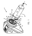
- FIG. 1 An embodiment of a front-loading injector system 5 of the present invention is illustrated in Figure 1 .
- Injector system 5 includes a powered injector 10 and a syringe 20 for injection of, for example, a contrast medium.
- An example of an injector 10 suitable for use in the present invention is the MEDRAD VISTRON CT ® injector available from Medrad, Inc. of Indianola, Pennsylvania.
- the present invention may be used in connection with other fluid delivery systems, including injectors and infusion pumps for magnetic resonance imaging, computed tomography, ultrasound and angiographic procedures.
- injector housing 30 of injector 10 preferably includes a first drive member or piston 40 therein which cooperates with a syringe plunger (not shown in Figure 1 ; see, for example, Figure 7C) slideably disposed in syringe 20 to inject a fluid from the interior of syringe 20 into a patient.
- a syringe plunger (not shown in Figure 1 ; see, for example, Figure 7C) slideably disposed in syringe 20 to inject a fluid from the interior of syringe 20 into a patient.
- axial refer generally to, for example, an axis A around which syringe 20 and piston 40 are preferably formed (although not necessarily symmetrically therearound) and to directions collinear with or parallel to axis A.
- proximal refer generally to an axial or a longitudinal direction toward the end of injector housing 30 opposite the end to which syringe 20 is mounted.
- distal refer generally to an axial or a longitudinal direction toward a syringe tip 26 of syringe 20 (from which pressurized fluid exits syringe 20).
- radial refers generally to a direction normal to an axis such as axis A.
- Syringe 20 is preferably removably connected to injector 10 as described, for example, in U.S. Patent No. 5,383,858 .
- front-loading injector 10 preferably includes a front portion or faceplate 60 having a first opening 62 formed therein.
- Piston 40 is reciprocally mounted within injector 10 and is extendible through opening 62.
- Piston 40 preferably includes a piston flange or head 44 to assist in forming a connection with the syringe plunger.
- Faceplate 60 includes receiving slots 66a and 66b, which are preferably positioned opposite one another around opening 62.
- Receiving flanges 68a and 68b are preferably positioned opposite one another and between receiving slots 66a and 66b and extend inwardly into opening 62.
- the rearward end of syringe 20 preferably includes a mounting mechanism such as a pair of mounting flanges 22a and 22b for mounting syringe 20 in a desired position relative to the front wall 60 of injector 10.
- Flange 22b is not shown in Figure 1 but is generally identical to flange 22a and positioned opposite flange 22a.
- Mounting flanges 22a and 22b may include one or more indicators (not shown), such as one or more detent(s), bar code(s), protrusion(s) or notch(es), which provide information to the injector 10, for example, about the type of syringe 20 and injection fluid being used.
- injector 10 preferably includes any suitable detection mechanism (not shown) such as one or more sensors for reading information from the indicators.
- Piston flange 44 preferably engages a capture mechanism on the rear of the syringe plunger (as, for example, described in U.S. Patent No. 5,383,858 ).
- Injector 10 may include a stop mechanism (not shown), for example, extending from at least one of the retaining slots 68a and 68b, to prevent rotation of syringe 20 more than 90 degrees.
- Tactile, visual or audible feedback can be provided to the operator via, for example, cooperating members on syringe 20 and injector 10 to inform the operator that a secure connection has been achieved.
- advancing piston 40 in a forward direction will apply a motive force to the plunger to advance the plunger forward within syringe 20, thereby forcing the contents of syringe 20 out of syringe tip 26 into the fluid path to the patient.
- Retracting piston 40 in a rearward direction will cause the plunger to move rearward within syringe 20, thereby drawing fluid into syringe 20.
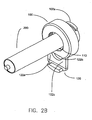
- FIGS 2A-2C illustrate one embodiment of a syringe interface/adapter 100 that is preferably attachable to injector 10 in a similar manner as described above for attachment of syringe 20 to injector 10.
- a rearward portion or section of adapter 100 preferably includes a mounting mechanism such as a pair of mounting flanges 102a and 102b (not shown, but symmetrical to and positioned generally 180° opposite of mounting flange 102a) for mounting adapter 100 in a desired position relative to the front wall 60 of injector 10.
- Mounting flanges 102a and 102b may include indicators, such as detents or notches as described above, which provide information to injector 10 about the type of adapter and/or syringe being used.
- adapter 100 To attach adapter 100 to injector 10, the rearward end of adapter 100 is inserted into injector opening 62 such that mounting flanges 102a and 102b are inserted into receiving slots 66a and 66b, respectively.
- the operator preferably rotates adapter 100 approximately 90 degrees such that mounting flanges 102a and 102b move behind and are engaged by receiving flanges 68a and 68b, respectively.
- a stop mechanism may, for example, extend from at least one of the retaining slots 68a and 68b, to prevent rotation of adapter 100 more than 90 degrees.
- tactile, visual or audible feedback can be provided to the operator via, for example, cooperating members on adapter 100 and injector 10 to inform the operator that a secure connection has been achieved.
- Adapter 100 can, for example, be used to attach a syringe 200 including, for example, a rearward flange 220, to injector 10.
- a syringe 200 including, for example, a rearward flange 220, to injector 10.
- rearward flange 220 has a generally circular shape with straight or flattened, opposing sides 222a and 222b.
- advancing piston 40 in a forward direction applies a motive force to a plunger 210 (see, for example, Figure 7C) within syringe 200 through passage 110 in adapter 100 to advance syringe plunger 210 forward within syringe 200, thereby forcing contrast medium in syringe 200 out of syringe tip 250 into the fluid path to the patient.
- a plunger 210 see, for example, Figure 7C
- syringe 200 is first aligned with passage 110 in adapter 100.
- syringe 200 is then moved rearward until flange 220 is positioned to the rear of abutment members 122a and 122b.
- movement of syringe 200 to the rear can involve the attachment of a syringe plunger 210 to a plunger adapter 800 (see Figure 8E) via, for example, rotating syringe 200 to thread syringe plunger 210 onto plunger adapter 800.
- retaining member 120 is slid upward or radially inward to a closed or secure position as illustrated in Figure 2C .
- advancing piston 40 in a forward direction will cause the forward surface of syringe flange 220 to abut the rearward surfaces of abutment members 122a and 122b of retaining member 120 as well as the rearward surface of lower abutment member 122c (which connects abutment member 122a and 122b to form a generally U-shaped abutment member in retaining member 120), thereby retaining syringe 200 within adapter 100.
- Adapter 100 can also include a rear abutment surface 140 to assist in properly positioning syringe 200 within adapter 100. Should piston 40 be retracted, the rear surface of syringe flange 220 abuts rear abutment surface 140 to prevent syringe 200 from moving rearward within adapter 100.
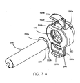
- FIG. 3A-3C Another embodiment of an adapter 500 of the present invention is illustrated in Figures 3A-3C .
- Adapter 500 is similar in operation to adapter 100.
- adapter 500 includes two, generally opposing sliding retaining members 520a and 520b.
- syringe 200 is first aligned with passage 510 in adapter 500.
- no specific orientation of generally flat sides 222a and 222b of syringe flange 220 is required with respect to the orientation of sliding retaining members 520a and 520b, which are slideably positioned within passages 530a and 530b in adapter 500.
- syringe 200 is moved rearward until flange 220 is positioned to the rear of U-shaped abutment members 522a and 522b of sliding retaining members 520a and 520b, respectively.
- rearward movement of syringe 200 can include attachment (for example, by rotation relative thereto) of syringe plunger 210 to plunger adapter 800.
- Adapter 500 can also include a rear abutment surface 540.
- the two sliding retaining members 520a and 520b of adapter 500 fully engage or encompass rear flange 220 of syringe 200 (that is, U-shaped abutment members 522a and 522b contact the forward surface of flange 220 around the entire perimeter of flange 220). Because the contact is symmetrical about the axis of syringe 200, advancing piston 40 does not result in bending moments upon syringe 200, as described above for adapter 400.
- full contact around the perimeter of syringe flange 220 by adapter 500 distributes forces over the entirety of syringe flange 220 and thus enables syringe flange 220 to endure greater force without distortion or failure as compared to the case in which only part of flange 220 is contacted by a retaining or abutment member.
- full contact with syringe flange 220 enables manufacture of syringe 200 from materials that might fail under conditions of only partial contact of a retaining member with syringe flange 220.
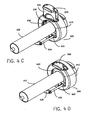
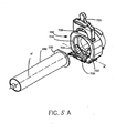
- FIGS 4A-4D illustrate another embodiment of an adapter 600 including a sliding retaining member 620 having a generally U-shaped abutment member 622 that operates in generally the same manner as sliding retaining member 520a described above.
- Adapter 600 also includes a retaining carriage 630 that is generally axially slideable within passage 610 of adapter 600 via passages 632 (see Figures 4C and 4D ) that cooperate with or slide upon guide rails 634. End member 636 prevents carriage 630 from being removed from guide rails 634.
- Retaining carriage 630 also includes a generally U-shaped abutment member 638 (similar to retention or abutment member 322 of adapter 300) in which syringe flange 220 is preferably seated (and, in some embodiments, as discussed above in connection with retention member 322, rotatably (about its axis) seated).
- abutment member 638 similar to retention or abutment member 322 of adapter 300
- syringe flange 220 is preferably seated (and, in some embodiments, as discussed above in connection with retention member 322, rotatably (about its axis) seated).
- a syringe 200 is seated within retention or abutment member 638 of carriage 630.
- Carriage 630 is then slid rearward within adapter 600 to the position illustrated in Figure 4C .
- abutment member 622 of retaining member 620 is in general alignment with syringe flange 220 and abutment member 638 so that retaining member 620 can be slid radially inward to engage flange 220 with abutment member 622 as illustrated in Figure 4D .
- abutment member 622 and abutment member 638 symmetrically and fully encompass or engage syringe flange 220 when in the closed or secured position of Figure 4D .
- Sliding retaining member 620 and carriage 630 can, for example, interlock to secure the adapter in a closed position.
- FIGS 5A-5G illustrate an embodiment of an adapter 700 that includes a sliding retaining member 720 having a generally U-shaped abutment member or retention member 722 that operates in a similar manner as described above for sliding retention member 622.
- Adapter 700 also includes a second retaining member 730 that pivots about an axis A' radially offset from, and oriented generally perpendicular to, axis A" of syringe 200 and adapter 700.
- syringe 200 is preferably aligned with passage 710 in adapter 700. Syringe 200 is then moved rearward so that the rear surface of syringe flange 220 contracts a contact member 732 of second retaining member 730 as illustrated in Figures 5B, 5C and 5F .
- Contact of flange 220 with contact member 732 and further rearward movement of syringe 200 causes second retaining member 730 to pivot or rock rearward about axis A' so that second retaining member 730 becomes generally vertically oriented (generally perpendicular to axis A") and generally in plane with retaining member 720.
- This position of syringe 200 within adapter 700 is shown in Figure 5D .
- abutment surface 734 of second retaining member 730 comes into contact with the forward surface of flange 220.
- retaining member 720 is slid radially inward (or downward in the orientation of Figures 5A through 5G ) to interlock with second retaining member 730 (via, for example, interlocking extending members 726 and 736) to secure syringe 200 within adapter 700.
- Retaining members 720 and 730 symmetrically and fully encompass syringe flange 220.
- Adapter 700 enables the removal of syringe 200 from adapter 700 without the rearward retraction of piston 40.
- first retaining member 720 can be slid radially outward and second retaining member 730 pivoted forward to fully release syringe 200.
- retaining member 730 can be biased in an open position using, for example, a spring loaded extension arm 740 attached to or in operative connection with retaining member 730.
- a spring loaded extension arm 740 attached to or in operative connection with retaining member 730.
- retaining member 730 is biased in an open or receiving position to receive another syringe.
- FIG. 6A illustrates the use of a plunger adapter 800 with injector 10, syringe 200 (including plunger 210) and syringe adapter 700 (as discussed in connection with Figures 5A through 5G ).
- piston 40 includes a flanged extension 46 on piston flange 44.
- Plunger adapter 800 includes a slot 810 adapted to receive flanged extension 46 therein to attach plunger adapter 800 to piston 40 as illustrated, for example, in Figure 6C .
- Flanged extension 46 can also include a depression 48 that cooperates with a biased detent mechanism in slot 810 (for example, a spring-loaded ball 820) to assist in forming a secure connection between plunger adapter 800 and piston 40.
- FIG. 6D illustrates injector 10 with syringe adapter 700 and plunger adapter 800 attached thereto.
- Plunger adapter 800 includes on the forward end thereof an attachment mechanism 830 for forming a connection with a capture member 212 on the rearward portion of plunger 210 (see Figures 5C and 6E ).
- plunger attachment mechanism 830 includes threading 832 that cooperates with mating threading on the interior of plunger capture member 212.
- syringe 200 proceeds generally as discussed above.
- syringe flange 220 makes contact with contact member 732 of second retaining member 730
- threaded plunger attachment mechanism 830 preferably also comes into contact with threaded plunger capture member 212.
- the user can rotate syringe 200 about its axis so that attachment mechanism 830 and capture member 212 form a secure connection.
- Rotating syringe 200 also causes syringe 200 to move rearward as attachment mechanism 830 is threaded onto capture member 212.
- Piston 40 and plunger adapter 800 are preferably properly positioned (using, for example, an appropriate positioning setting on injector 10), and syringe adapter 700, attachment mechanism 830 and capture member 212 are preferably properly dimensioned such that when plunger attachment mechanism 830 and capture member 212 are fully connected, syringe 220 has moved rearward into the position of Figures 5D and 5E .
- second retaining member 730 has pivoted to a generally vertical position. In this position, retaining member 720 can be slid radially inward to a closed position to secure syringe 200 within adapter 700.
- Plunger adapter 800 is also suitable for use with the other syringe adapters discussed above.
- FIG. 7A illustrates another embodiment of a syringe adapter 700' which is similar in operation to syringe adapter 700, except for the manner in which adapter 700' is attached to an injector syringe interface / release mechanism 4010.
- Release mechanism 4010 includes a connector housing 4024 which contains at least two elements that facilitate connection of syringe adapter 700' to an injector 4014.
- the first element is a flex ring 4026 disposed within release mechanism 4010 near front end 4020.
- the second element is a rotating ring 4028 disposed within release mechanism 4010 near rearward end 4016.
- Flex ring 4026 and rotating ring 4028 are adapted to cooperate with one another, as described in greater detail below, to permit connection and release of syringe adapter 700' (and, accordingly, syringe 200) to and from release mechanism 4010 (and, accordingly, to and from injector 4014).
- Injector 4014 and release mechanism 4010 are described in detail in PCT Publication No. WO 01/37903 and U.S. Patent Application Publication No. 2001-47153 .
- a flange or ridge 764' is preferably integrally formed on syringe adapter 700' toward rearward end 760' of syringe adapter 700'.
- Ridge 764' includes two parts, a sloping section 766' and a shoulder section 768' that is essentially perpendicular to axis A"' around which syringe adapter 700' is formed (although, not necessarily symmetrically therearound).
- At least one, and preferably two or more, extending tabs or projections 770' are provided at rearward end 760' of syringe adapter 700'. Tabs 770' engage grooves 4052 provided in ring 4028 as discussed below.
- slots, recesses or divots, etc. could be provided in rear end 760' of syringe adapter 700' and cooperating tabs or projections could be provided on the interior surface of rotating ring 4028.
- Release / connector mechanism 4010 includes, for example, a front plate 4054 and a rear plate 4056.
- Front plate 4054 and rear plate 4056 can, for example, be constructed of aluminum coated with a fluoropolymer (such as TuframTM, which is the product name of a fluoropolymer manufactured by the General Magna Plate Company).
- the fluoropolymer coating provides improved resistance to wear and also provides lubricity to the exterior surfaces of front plate 4054 and rear plate 4056. Lubricity is particularly advantageous because, when contrast medium crystallizes on the exterior surface of front plate 4054 or rear plate 4056, it easily flakes off of the surface when the surface is coated with the fluoropolymer.
- any suitable alternative coating material may be used on the exterior surface of front plate 4054 or rear plate 4056.
- a coating may not need to be applied to the surface of front plate 4054 or rear plate 4056 if either plate is made of a suitable material.
- front plate 4054 and rear plate 4056 are constructed of a high density plastic (an acetyl copolymer, for example) the material itself can provide resistance to caking of contrast media, similar to the fluoropolymer coating on aluminum.
Landscapes
- Health & Medical Sciences (AREA)
- Vascular Medicine (AREA)
- Engineering & Computer Science (AREA)
- Anesthesiology (AREA)
- Biomedical Technology (AREA)
- Heart & Thoracic Surgery (AREA)
- Hematology (AREA)
- Life Sciences & Earth Sciences (AREA)
- Animal Behavior & Ethology (AREA)
- General Health & Medical Sciences (AREA)
- Public Health (AREA)
- Veterinary Medicine (AREA)
- Infusion, Injection, And Reservoir Apparatuses (AREA)
Abstract
Claims (20)
- Interface de seringue pour fixer relâchablement une seringue (200) comprenant une bride (220) à un injecteur (10) comprenant un piston (40), l'interface de seringue (100; 500; 600; 700) comprenant un boîtier définissant un passage (110; 510; 610; 710) et un élément de retenue (120; 520a; 620; 720) disposé d'une manière coulissante dans le passage (110; 510; 610; 710), l'élément de retenue (120; 520a; 620; 720) étant apte à coulisser dans une direction généralement perpendiculaire à l'axe longitudinal (A") de la seringue (200) pour venir en prise avec au moins une portion de la bride de seringue (220),
caractérisée en ce que
l'élément de retenue (120; 520a; 602; 720) est apte à coulisser seulement linéairement dans une direction généralement perpendiculaire à l'axe longitudinal (A") de la seringue (200). - Interface de seringue selon la revendication 1, dans laquelle le boîtier comprend en outre une portion arrière comprenant un mécanisme de fixation, le mécanisme de fixation étant apte à fixer l'interface de seringue (100; 500; 600; 700) à l'injecteur (10).
- Interface de seringue selon la revendication 2, dans laquelle le mécanisme de fixation comprend une ou plusieurs brides de montage (102a, 102b).
- Interface de seringue selon la revendication 3, dans laquelle le mécanisme de fixation comprend en outre au moins une projection d'extension.
- Interface de seringue selon l'une quelconque des revendications 1 à 4, dans laquelle le boîtier comprend en outre un ou plusieurs indicateurs aptes à fournir des informations sur la seringue (200) à l'injecteur (10).
- Interface de seringue selon l'une quelconque des revendications 1 à 5, dans laquelle l'interface de seringue comprend un deuxième élément de retenue (520b) positionné d'une manière coulissante dans un passage dans l'interface de seringue (500) pour glisser dans une direction généralement perpendiculaire à l'axe (A") du piston (40), le premier élément de retenue (520a) étant généralement opposé au deuxième élément de retenue (520b), le premier élément de retenue (520a) et le deuxième élément de retenue (520b) étant aptes à venir en prise avec la bride de seringue (220) et à retenir la seringue (200) dans l'interface de seringue (500).
- Interface de seringue selon la revendication 6, dans laquelle le premier élément de retenue (520a) et le deuxième élément de retenue (520b) coopèrent pour une mise en prise avec la bride de seringue (220) autour de tout le périmètre de la bride de seringue (200).
- Interface de seringue selon l'une quelconque des revendications 1 à 5, dans laquelle l'interface de seringue comprend une cartouche (630) reliée d'une manière coulissante à l'interface de seringue (600) dans une direction (A") généralement parallèle au piston (40), le chariot (600) comprenant un élément de siège (638) apte à venir en prise avec une portion de la bride de seringue (220), le chariot (630) pouvant coulisser à une position arrière dans l'interface de seringue (600) à laquelle l'élément de retenue (620) peut coulisser radialement vers l'intérieur pour venir en prise avec une autre portion de la bride de seringue (220) et pour retenir la seringue (200) dans l'interface de seringue (600).
- Interface de seringue selon la revendication 8, dans laquelle le chariot (630) et l'élément de retenue (620) coopèrent pour une mise en prise de la bride de seringue (220) autour de tout le périmètre de la bride de seringue (220).
- Interface de seringue selon l'une quelconque des revendications 1 à 5, comprenant en outre un deuxième élément de retenue (730) fonctionnellement associé au boîtier, le deuxième élément de retenue (730) étant apte à pivoter autour d'un axe (A') généralement perpendiculaire à et décalé de l'axe (A") du piston (40) pour venir en prise avec une portion de la bride de seringue (220).
- Interface de seringue selon la revendication 10, dans laquelle le deuxième élément de retenue (730) pivote dans une direction arrière.
- Interface de seringue selon la revendication 10 ou 11, dans laquelle l'élément de retenue (720) et le deuxième élément de retenue (730) coopèrent pour une mise en prise de la bride de seringue (220) autour du périmètre entier de la bride de seringue (220).
- Interface de seringue selon les revendications 10 à 12, dans laquelle le deuxième élément de retenue (730) est sollicité vers une position ouverte.
- Interface de seringue selon les revendications 10 à 13, comprenant en outre un élément de contact (732) fonctionnellement associé au deuxième élément de retenue (730), l'élément de contact (732) étant apte à amener le deuxième élément de retenue (730) pour pivoter autour de l'axe (A') généralement perpendiculaire à et décalé de l'axe (A") du piston (40).
- Interface de seringue selon les revendications 1 à 14, dans laquelle l'élément de retenue comprend un élément de butée généralement en forme de U apte à venir en prise avec au moins une portion de la bride de seringue (220).
- Injecteur comprenant l'interface de seringue (100; 500; 600; 700) selon l'une quelconque des revendications 1 à 15.
- Injecteur selon la revendication 16, comprenant un mécanisme de montage sur un avant de l'injecteur (10) et un piston (40) déplaçable selon un mouvement alternatif par le mécanisme de montage.
- Procédé de fixation d'une seringue (200) comprenant une bride (220) à l'interface de seringue (100; 500; 600; 700) selon l'une quelconque des revendications 1 à 15, comprenant:insérer la bride de seringue (220) dans le boîtier de l'interface de seringue (100; 500; 600; 700); etfaire coulisser l'élément de retenue (120; 520a, 620, 720) radialement vers l'intérieur dans une direction généralement perpendiculaire à un axe (A") d'un piston d'injecteur (40) pour une mise en prise avec au moins une portion de la bride de seringue (220).
- Procédé selon la revendication 17, comprenant en outre:faire pivoter le deuxième élément de retenue (730) autour d'un axe (A') généralement perpendiculaire à et décalé de l'axe (A'#) du piston d'injecteur (40) pour une mise en prise avec une portion de la bride de seringue (220).
- Procédé selon la revendication 17 ou 18, comprenant en outre:faire tourner la seringue (200) pour fixer un plongeur (210) de la seringue (200) au piston d'injecteur (40).
Applications Claiming Priority (3)
| Application Number | Priority Date | Filing Date | Title |
|---|---|---|---|
| US26252001P | 2001-01-18 | 2001-01-18 | |
| US262520P | 2001-01-18 | ||
| PCT/US2002/001657 WO2002056945A2 (fr) | 2001-01-18 | 2002-01-18 | Interfaces et adaptateurs de seringue pour injecteurs medicaux |
Publications (2)
| Publication Number | Publication Date |
|---|---|
| EP1351729A2 EP1351729A2 (fr) | 2003-10-15 |
| EP1351729B1 true EP1351729B1 (fr) | 2011-07-06 |
Family
ID=22997848
Family Applications (1)
| Application Number | Title | Priority Date | Filing Date |
|---|---|---|---|
| EP02702043A Expired - Lifetime EP1351729B1 (fr) | 2001-01-18 | 2002-01-18 | Interfaces de seringue |
Country Status (5)
| Country | Link |
|---|---|
| US (1) | US7273477B2 (fr) |
| EP (1) | EP1351729B1 (fr) |
| JP (1) | JP4245350B2 (fr) |
| CN (1) | CN100473425C (fr) |
| WO (1) | WO2002056945A2 (fr) |
Families Citing this family (87)
| Publication number | Priority date | Publication date | Assignee | Title |
|---|---|---|---|---|
| US8034026B2 (en) | 2001-05-18 | 2011-10-11 | Deka Products Limited Partnership | Infusion pump assembly |
| EP1815879A3 (fr) | 2001-05-18 | 2007-11-14 | Deka Products Limited Partnership | Perfuseur pour pompe à liquide |
| US7041084B2 (en) | 2001-05-24 | 2006-05-09 | Fojtik Shawn P | Hand-held, hand operated power syringe and methods |
| GB0224505D0 (en) * | 2002-10-22 | 2002-11-27 | Medical House The Plc | Needles injection device |
| FR2850283B1 (fr) * | 2003-01-28 | 2005-12-16 | Sedat | Dispositif de support de seringue angiographique et ses combinaisons avec une seringue angiographique et avec un injecteur angiographique |
| US20050020980A1 (en) * | 2003-06-09 | 2005-01-27 | Yoshio Inoue | Coupling system for an infusion pump |
| FR2880809B1 (fr) * | 2005-01-17 | 2007-02-23 | Fresenius Vial Soc Par Actions | Dispositif de retenue pour bloquer la tete de piston d'une seringue sur le poussoir d'un pousse seringue |
| ATE415181T1 (de) * | 2005-02-23 | 2008-12-15 | Mallinckrodt Inc | Stützplattenadapter für einen spritzenkolben |
| DE102005045391A1 (de) * | 2005-09-23 | 2007-03-29 | Medtron Ag | Spritzenaufnahme für einen medizinischen Injektor |
| US11318249B2 (en) | 2006-02-09 | 2022-05-03 | Deka Products Limited Partnership | Infusion pump assembly |
| US11478623B2 (en) | 2006-02-09 | 2022-10-25 | Deka Products Limited Partnership | Infusion pump assembly |
| US11497846B2 (en) | 2006-02-09 | 2022-11-15 | Deka Products Limited Partnership | Patch-sized fluid delivery systems and methods |
| US11364335B2 (en) | 2006-02-09 | 2022-06-21 | Deka Products Limited Partnership | Apparatus, system and method for fluid delivery |
| US12274857B2 (en) | 2006-02-09 | 2025-04-15 | Deka Products Limited Partnership | Method and system for shape-memory alloy wire control |
| CN104162200B (zh) | 2006-02-09 | 2018-03-27 | 德卡产品有限公司 | 外围系统 |
| US12370305B2 (en) | 2006-02-09 | 2025-07-29 | Deka Products Limited Partnership | Patch-sized fluid delivery systems and methods |
| US12070574B2 (en) | 2006-02-09 | 2024-08-27 | Deka Products Limited Partnership | Apparatus, systems and methods for an infusion pump assembly |
| US12151080B2 (en) | 2006-02-09 | 2024-11-26 | Deka Products Limited Partnership | Adhesive and peripheral systems and methods for medical devices |
| US11027058B2 (en) | 2006-02-09 | 2021-06-08 | Deka Products Limited Partnership | Infusion pump assembly |
| US9492606B2 (en) | 2006-02-09 | 2016-11-15 | Deka Products Limited Partnership | Apparatus, system and methods for an infusion pump assembly |
| JPWO2007122808A1 (ja) * | 2006-04-19 | 2009-09-03 | 株式会社根本杏林堂 | シリンジホルダー、薬液注入装置、薬液注入装置の制御方法 |
| WO2007130061A1 (fr) * | 2006-05-10 | 2007-11-15 | Medrad, Inc. | Injecteur médical à chargement frontal et seringues correspondantes |
| US20080098564A1 (en) * | 2006-10-24 | 2008-05-01 | Fojtik Shawn P | Locking Hinges for Syringe Handles, Syringes Including Locking Hinges, and Associated Methods |
| US8672893B2 (en) | 2007-10-23 | 2014-03-18 | Control Medical Technology, Llc | Syringe with rotatable element, aspiration systems including the syringe, and associated methods |
| US10058656B2 (en) | 2006-10-24 | 2018-08-28 | Pmt Partners, Llc | Syringe with rotatable element, systems including the syringe, and associated methods |
| EP2114493B1 (fr) * | 2006-11-22 | 2011-10-05 | Mallinckrodt LLC | Adaptateur universel pour un piston de seringue |
| US8454560B2 (en) * | 2006-12-05 | 2013-06-04 | Mallinckrodt Llc | Syringe mount for a medical fluid injector |
| EP2121077A1 (fr) | 2007-02-09 | 2009-11-25 | Deka Products Limited Partnership | Ensemble d'insertion automatisé |
| US20090088702A1 (en) * | 2007-10-01 | 2009-04-02 | Fojtik Shawn P | Methods for manually injecting/aspirating fluids through small diameter catheters and needles and manual injection/aspiration systems including small diameter catheters and needles |
| US11191931B2 (en) * | 2007-10-01 | 2021-12-07 | Pmt Partners, Llc | Methods for manually injecting/aspirating fluids through small diameter catheters and needles and manual injection/aspiration systems including small diameter catheters and needles |
| WO2009073644A1 (fr) * | 2007-12-07 | 2009-06-11 | Mallinckrodt Inc. | Système de montage pour seringue d'injecteur |
| EP2227276B1 (fr) * | 2007-12-07 | 2019-05-01 | Liebel-Flarsheim Company LLC | Support pour seringue de systèmes d'injecteurs de type pousserpour installer |
| US10188787B2 (en) | 2007-12-31 | 2019-01-29 | Deka Products Limited Partnership | Apparatus, system and method for fluid delivery |
| WO2009088956A2 (fr) | 2007-12-31 | 2009-07-16 | Deka Products Limited Partnership | Système de pompe à perfusion |
| US8900188B2 (en) | 2007-12-31 | 2014-12-02 | Deka Products Limited Partnership | Split ring resonator antenna adapted for use in wirelessly controlled medical device |
| US12447265B2 (en) | 2007-12-31 | 2025-10-21 | Deka Products Limited Partnership | Apparatus, system and method for fluid delivery |
| CN110251769B (zh) | 2007-12-31 | 2022-04-01 | 德卡产品有限公司 | 输注泵组件 |
| US8881774B2 (en) | 2007-12-31 | 2014-11-11 | Deka Research & Development Corp. | Apparatus, system and method for fluid delivery |
| US10080704B2 (en) | 2007-12-31 | 2018-09-25 | Deka Products Limited Partnership | Apparatus, system and method for fluid delivery |
| US9456955B2 (en) | 2007-12-31 | 2016-10-04 | Deka Products Limited Partnership | Apparatus, system and method for fluid delivery |
| US7967785B2 (en) * | 2008-07-14 | 2011-06-28 | Nipro Healthcare Systems, Llc | Insulin reservoir detection via magnetic switching |
| WO2010031059A2 (fr) | 2008-09-15 | 2010-03-18 | Deka Products Limited Partnership | Systèmes et procédés de distribution de fluides |
| CA2680921C (fr) * | 2008-09-30 | 2017-02-28 | Animas Corporation | Capuchon de cartouche a ressort |
| US8708376B2 (en) | 2008-10-10 | 2014-04-29 | Deka Products Limited Partnership | Medium connector |
| US8262616B2 (en) | 2008-10-10 | 2012-09-11 | Deka Products Limited Partnership | Infusion pump assembly |
| US9180245B2 (en) | 2008-10-10 | 2015-11-10 | Deka Products Limited Partnership | System and method for administering an infusible fluid |
| US8016789B2 (en) | 2008-10-10 | 2011-09-13 | Deka Products Limited Partnership | Pump assembly with a removable cover assembly |
| US12370327B2 (en) | 2008-10-10 | 2025-07-29 | Deka Products Limited Partnership | Infusion pump methods, systems and apparatus |
| US8267892B2 (en) | 2008-10-10 | 2012-09-18 | Deka Products Limited Partnership | Multi-language / multi-processor infusion pump assembly |
| US12186531B2 (en) | 2008-10-10 | 2025-01-07 | Deka Products Limited Partnership | Infusion pump assembly |
| US8066672B2 (en) | 2008-10-10 | 2011-11-29 | Deka Products Limited Partnership | Infusion pump assembly with a backup power supply |
| US8223028B2 (en) | 2008-10-10 | 2012-07-17 | Deka Products Limited Partnership | Occlusion detection system and method |
| US8968246B2 (en) * | 2009-03-18 | 2015-03-03 | Nemoto Kyorindo Co., Ltd. | Syringe adapter |
| US9242040B2 (en) | 2009-04-23 | 2016-01-26 | Bayer Healthcare Llc | Syringe assemblies, methods of forming syringe assemblies and adapters for forming syringe assemblies |
| JP2013501583A (ja) * | 2009-08-13 | 2013-01-17 | マリンクロッド エルエルシー | 電動注入器シリンジアセンブリ |
| CA2771085A1 (fr) | 2009-08-13 | 2011-02-17 | Mallinckrodt Llc | Ensemble seringue a injecteur de puissance |
| CA2787178C (fr) | 2010-01-22 | 2019-02-12 | Deka Products Limited Partnership | Procede et systeme pour le controle d'un fil en acier allie a memoire de forme |
| JP5684490B2 (ja) * | 2010-04-23 | 2015-03-11 | バイエル メディカル ケア インコーポレーテッド | シリンジアセンブリ、シリンジアセンブリを形成する方法、及びシリンジアセンブリを形成するアダプタ |
| US11524151B2 (en) | 2012-03-07 | 2022-12-13 | Deka Products Limited Partnership | Apparatus, system and method for fluid delivery |
| WO2015003145A1 (fr) | 2013-07-03 | 2015-01-08 | Deka Products Limited Partnership | Appareil, système et procédé pour administrer un fluide |
| WO2016049607A1 (fr) | 2014-09-25 | 2016-03-31 | Pmt Partners, Llc | Seringue avec poignée rotative et systèmes et procédés associés |
| US9199033B1 (en) | 2014-10-28 | 2015-12-01 | Bayer Healthcare Llc | Self-orienting syringe and syringe interface |
| NO2689315T3 (fr) | 2014-10-28 | 2018-04-14 | ||
| CN107106761B (zh) | 2014-10-28 | 2020-11-03 | 拜耳医药保健有限公司 | 自定向压力护套以及压力护套到注射器的接口 |
| RU2017118366A (ru) | 2014-10-28 | 2018-11-30 | БАЙЕР ХелсКер ЛЛСи | Самоориентирующийся кожух высокого давления и механизм стыковки кожуха высокого давления и инъектора |
| EP3374002A1 (fr) | 2015-11-13 | 2018-09-19 | Bayer Healthcare LLC | Ensemble seringue emboîtée |
| US10821233B2 (en) * | 2015-12-30 | 2020-11-03 | Baxter Corporation Englewood | Syringe gripping apparatus and method |
| US10596321B2 (en) * | 2016-04-08 | 2020-03-24 | Allergan, Inc. | Aspiration and injection device |
| AU2017345167B2 (en) * | 2016-10-17 | 2022-12-15 | Bayer Healthcare Llc | Fluid injector with syringe engagement mechanism |
| WO2018140341A1 (fr) | 2017-01-24 | 2018-08-02 | Bayer Healthcare Llc | Systèmes d'injecteur et adaptateurs de seringue destinés à être utilisés avec lesdits systèmes |
| CN106913937B (zh) * | 2017-04-21 | 2022-07-22 | 苏州恒瑞迪生医疗科技有限公司 | 一种针筒及实现该针筒快速装载和释放的装置 |
| WO2019055497A1 (fr) | 2017-09-13 | 2019-03-21 | Bayer Healthcare Llc | Capuchon coulissant de seringue pour remplissage et distribution séparés |
| US11191893B2 (en) | 2018-01-31 | 2021-12-07 | Bayer Healthcare Llc | System and method for syringe engagement with injector |
| US11523972B2 (en) | 2018-04-24 | 2022-12-13 | Deka Products Limited Partnership | Apparatus, system and method for fluid delivery |
| AU2019340438A1 (en) | 2018-09-11 | 2021-03-04 | Bayer Healthcare Llc | Syringe retention feature for fluid injector system |
| CN109847152A (zh) * | 2019-02-16 | 2019-06-07 | 山东中医药大学 | 一种医用针筒固定系统 |
| IL314250A (en) | 2020-02-21 | 2024-09-01 | Bayer Healthcare Llc | Fluid path connectors for administering medical fluids |
| EP4110452B1 (fr) | 2020-02-28 | 2024-10-16 | Bayer HealthCare LLC | Set de mélange de fluid |
| WO2021183489A1 (fr) * | 2020-03-10 | 2021-09-16 | Zyno Medical, Llc | Seringue de haute précision ayant une unité pompe amovible |
| WO2021188460A1 (fr) | 2020-03-16 | 2021-09-23 | Bayer Healthcare Llc | Appareil d'arrêt pour trajets de fluide d'injecteur d'angiographie |
| CN115697435B (zh) | 2020-06-18 | 2026-03-03 | 拜耳医药保健有限责任公司 | 用于血管造影注入器流体路径的在线气泡悬浮装置 |
| KR20240164970A (ko) | 2020-08-11 | 2024-11-21 | 바이엘 헬쓰케어 엘엘씨 | 혈관 조영술 주사기의 피처 |
| EP4255525A2 (fr) | 2020-12-01 | 2023-10-11 | Bayer HealthCare, LLC | Cassette pour la rétention de composants de trajet de fluide pour système d'injecteur de fluide |
| EP4355382A1 (fr) | 2021-06-17 | 2024-04-24 | Bayer Healthcare LLC | Système et procédé de détection de type de fluide dans un tube pour appareil d'injection de fluide |
| KR20230023153A (ko) * | 2021-08-10 | 2023-02-17 | 주식회사 덴티스 | 치조골을 천공할 때 발생되는 소음 및 마찰력을 감소시키기 위한 무통주사기 |
| US20240399055A1 (en) | 2021-09-30 | 2024-12-05 | Guerbet | Injection device receiving a syringe |
| DE102022132708A1 (de) * | 2022-12-08 | 2024-06-13 | B. Braun Melsungen Aktiengesellschaft | Medizinische Fluidpumpe mit einem Antriebskopf |
Family Cites Families (15)
| Publication number | Priority date | Publication date | Assignee | Title |
|---|---|---|---|---|
| US4006736A (en) * | 1974-11-27 | 1977-02-08 | Medrad, Inc. | Angiographic injector |
| ATE51525T1 (de) * | 1984-06-06 | 1990-04-15 | Medrad Inc | Angiographie-injektor und mit diesem verwendbare angiograhie-spritze. |
| US5383858B1 (en) * | 1992-08-17 | 1996-10-29 | Medrad Inc | Front-loading medical injector and syringe for use therewith |
| US5779675A (en) * | 1995-08-25 | 1998-07-14 | Medrad, Inc. | Front load pressure jacket system with syringe holder |
| US5520653A (en) * | 1995-09-01 | 1996-05-28 | Medrad, Inc. | Syringe adapter for front-loading medical injector |
| JP3429922B2 (ja) * | 1995-10-30 | 2003-07-28 | スーガン株式会社 | シリンジ固定用補助器具 |
| US6336913B1 (en) | 1996-03-29 | 2002-01-08 | Medrad, Inc. | Front-loading syringe adapter for front-loading medical injector |
| DE19621394C1 (de) | 1996-05-28 | 1998-01-22 | Claus H Dr Ing Backes | Vorrichtung zur Aufnahme von Injektionszylindern für den Einsatz in maschinellen Hochdruckinjektionsgeräten |
| US5913844A (en) * | 1997-06-17 | 1999-06-22 | Liebel-Flarsheim Company | Power injector and method providing removal of used disposable syringe |
| US5865805A (en) * | 1997-07-16 | 1999-02-02 | Liebel-Flarsheim Company | Power injector and side loadable syringe support therefor for plunger pushrod type syringes |
| EP0919251B1 (fr) | 1997-11-26 | 2007-01-17 | Liebel-Flarsheim Company | Injecteur à chargement frontal et méthode pour le chargement d'une seringue pourvue d'un rebord |
| WO2001008727A1 (fr) | 1999-07-30 | 2001-02-08 | Medrad, Inc. | Systemes d'injecteurs et adaptateurs de seringue s'utilisant avec ces systemes |
| AU1786601A (en) * | 1999-11-24 | 2001-06-04 | Medrad, Inc. | Front-loading medical injector and syringes, syringe interfaces, syringe adapters and syringe plungers for use therewith |
| US6652489B2 (en) * | 2000-02-07 | 2003-11-25 | Medrad, Inc. | Front-loading medical injector and syringes, syringe interfaces, syringe adapters and syringe plungers for use therewith |
| EP1351730B1 (fr) * | 2001-01-18 | 2006-06-28 | Medrad, Inc. | Interfaces et adaptateurs de seringue pour injecteurs medicaux |
-
2002
- 2002-01-18 EP EP02702043A patent/EP1351729B1/fr not_active Expired - Lifetime
- 2002-01-18 JP JP2002557452A patent/JP4245350B2/ja not_active Expired - Fee Related
- 2002-01-18 CN CNB028037170A patent/CN100473425C/zh not_active Expired - Fee Related
- 2002-01-18 WO PCT/US2002/001657 patent/WO2002056945A2/fr not_active Ceased
- 2002-01-18 US US10/466,413 patent/US7273477B2/en not_active Expired - Lifetime
Also Published As
| Publication number | Publication date |
|---|---|
| JP2005504556A (ja) | 2005-02-17 |
| WO2002056945A8 (fr) | 2002-10-03 |
| US7273477B2 (en) | 2007-09-25 |
| EP1351729A2 (fr) | 2003-10-15 |
| CN100473425C (zh) | 2009-04-01 |
| CN1638827A (zh) | 2005-07-13 |
| WO2002056945A3 (fr) | 2002-12-12 |
| JP4245350B2 (ja) | 2009-03-25 |
| WO2002056945A2 (fr) | 2002-07-25 |
| US20040116893A1 (en) | 2004-06-17 |
Similar Documents
| Publication | Publication Date | Title |
|---|---|---|
| EP1351729B1 (fr) | Interfaces de seringue | |
| EP1351730B1 (fr) | Interfaces et adaptateurs de seringue pour injecteurs medicaux | |
| US6743205B2 (en) | Injector systems and syringe adapters for use therewith | |
| US7497843B1 (en) | Syringe interfaces, syringe adapters and injector systems | |
| US11596735B2 (en) | Medical injector system | |
| CN102123752B (zh) | 具有rfid天线的动力注射器针筒夹持组件 | |
| US7553294B2 (en) | Syringe plunger sensing mechanism for a medical injector | |
| EP2243505B1 (fr) | Dispositifs à seringue, procédés de formations de dispositifs à seringue | |
| US7419478B1 (en) | Front-loading syringe for medical injector having a flexible syringe retaining ring | |
| US20040039368A1 (en) | Devices, systems and methods for injecting multiple fluids into a patient | |
| WO2020055785A1 (fr) | Élément de retenue de seringue pour système d'injecteur de fluide | |
| CN102573964A (zh) | 动力注射器针筒组件 | |
| CN114502214A (zh) | 用于血管造影术流体注入器的压力护套和注射器保持特征 | |
| US20030045789A1 (en) | Syringe interfaces for variable size syringes and syringe drive including such syringe interfaces | |
| CN102573951A (zh) | 动力注射器针筒组件 | |
| HK1241303A1 (en) | Front-loading medical injector and syringes, syringe interfaces, syringe adapters and syringe plungers for use therewith |
Legal Events
| Date | Code | Title | Description |
|---|---|---|---|
| PUAI | Public reference made under article 153(3) epc to a published international application that has entered the european phase |
Free format text: ORIGINAL CODE: 0009012 |
|
| 17P | Request for examination filed |
Effective date: 20030710 |
|
| AK | Designated contracting states |
Kind code of ref document: A2 Designated state(s): AT BE CH CY DE DK ES FI FR GB GR IE IT LI LU MC NL PT SE TR |
|
| 17Q | First examination report despatched |
Effective date: 20050810 |
|
| RTI1 | Title (correction) |
Free format text: SYRINGE INTERFACES |
|
| GRAP | Despatch of communication of intention to grant a patent |
Free format text: ORIGINAL CODE: EPIDOSNIGR1 |
|
| RBV | Designated contracting states (corrected) |
Designated state(s): DE FR IT NL |
|
| GRAS | Grant fee paid |
Free format text: ORIGINAL CODE: EPIDOSNIGR3 |
|
| GRAA | (expected) grant |
Free format text: ORIGINAL CODE: 0009210 |
|
| AK | Designated contracting states |
Kind code of ref document: B1 Designated state(s): DE FR IT NL |
|
| REG | Reference to a national code |
Ref country code: DE Ref legal event code: R096 Ref document number: 60240440 Country of ref document: DE Effective date: 20110825 |
|
| REG | Reference to a national code |
Ref country code: NL Ref legal event code: T3 |
|
| PLBE | No opposition filed within time limit |
Free format text: ORIGINAL CODE: 0009261 |
|
| STAA | Information on the status of an ep patent application or granted ep patent |
Free format text: STATUS: NO OPPOSITION FILED WITHIN TIME LIMIT |
|
| 26N | No opposition filed |
Effective date: 20120411 |
|
| REG | Reference to a national code |
Ref country code: DE Ref legal event code: R097 Ref document number: 60240440 Country of ref document: DE Effective date: 20120411 |
|
| REG | Reference to a national code |
Ref country code: DE Ref legal event code: R082 Ref document number: 60240440 Country of ref document: DE Representative=s name: RECHTS- UND PATENTANWAELTE LORENZ SEIDLER GOSS, DE |
|
| REG | Reference to a national code |
Ref country code: NL Ref legal event code: TD Effective date: 20140418 |
|
| REG | Reference to a national code |
Ref country code: DE Ref legal event code: R081 Ref document number: 60240440 Country of ref document: DE Owner name: BAYER MEDICAL CARE INC., INDIANOLA, US Free format text: FORMER OWNER: MEDRAD, INC., INDIANOLA, PA., US Effective date: 20140331 Ref country code: DE Ref legal event code: R081 Ref document number: 60240440 Country of ref document: DE Owner name: BAYER MEDICAL CARE INC., INDIANOLA, US Free format text: FORMER OWNER: MEDRAD, INC., INDIANOLA, PA., US Effective date: 20110706 Ref country code: DE Ref legal event code: R082 Ref document number: 60240440 Country of ref document: DE Representative=s name: LORENZ SEIDLER GOSSEL RECHTSANWAELTE PATENTANW, DE Effective date: 20140331 Ref country code: DE Ref legal event code: R081 Ref document number: 60240440 Country of ref document: DE Owner name: BAYER MEDICAL CARE INC., US Free format text: FORMER OWNER: MEDRAD, INC., INDIANOLA, US Effective date: 20140331 Ref country code: DE Ref legal event code: R082 Ref document number: 60240440 Country of ref document: DE Representative=s name: RECHTS- UND PATENTANWAELTE LORENZ SEIDLER GOSS, DE Effective date: 20140331 Ref country code: DE Ref legal event code: R081 Ref document number: 60240440 Country of ref document: DE Owner name: BAYER MEDICAL CARE INC., US Free format text: FORMER OWNER: MEDRAD, INC., INDIANOLA, US Effective date: 20110706 Ref country code: DE Ref legal event code: R081 Ref document number: 60240440 Country of ref document: DE Owner name: BAYER HEALTHCARE LLC, WHIPPANY, US Free format text: FORMER OWNER: MEDRAD, INC., INDIANOLA, PA., US Effective date: 20110706 Ref country code: DE Ref legal event code: R081 Ref document number: 60240440 Country of ref document: DE Owner name: BAYER HEALTHCARE LLC, WHIPPANY, US Free format text: FORMER OWNER: MEDRAD, INC., INDIANOLA, PA., US Effective date: 20140331 |
|
| REG | Reference to a national code |
Ref country code: FR Ref legal event code: CA Effective date: 20141118 Ref country code: FR Ref legal event code: CD Owner name: BAYER MEDICAL CARE INC., US Effective date: 20141118 |
|
| REG | Reference to a national code |
Ref country code: FR Ref legal event code: PLFP Year of fee payment: 15 |
|
| PGFP | Annual fee paid to national office [announced via postgrant information from national office to epo] |
Ref country code: NL Payment date: 20160111 Year of fee payment: 15 |
|
| PGFP | Annual fee paid to national office [announced via postgrant information from national office to epo] |
Ref country code: IT Payment date: 20160127 Year of fee payment: 15 |
|
| REG | Reference to a national code |
Ref country code: FR Ref legal event code: PLFP Year of fee payment: 16 |
|
| REG | Reference to a national code |
Ref country code: DE Ref legal event code: R082 Ref document number: 60240440 Country of ref document: DE Representative=s name: LORENZ SEIDLER GOSSEL RECHTSANWAELTE PATENTANW, DE Ref country code: DE Ref legal event code: R081 Ref document number: 60240440 Country of ref document: DE Owner name: BAYER HEALTHCARE LLC, WHIPPANY, US Free format text: FORMER OWNER: BAYER MEDICAL CARE INC., INDIANOLA, PA., US |
|
| REG | Reference to a national code |
Ref country code: NL Ref legal event code: PD Owner name: BAYER HEALTHCARE LLC; US Free format text: DETAILS ASSIGNMENT: CHANGE OF OWNER(S), ASSIGNMENT; FORMER OWNER NAME: BAYER MEDICAL CARE INC. Effective date: 20170215 |
|
| REG | Reference to a national code |
Ref country code: FR Ref legal event code: TP Owner name: BAYER HEALTHCARE LLC, US Effective date: 20170621 |
|
| REG | Reference to a national code |
Ref country code: NL Ref legal event code: MM Effective date: 20170201 |
|
| PG25 | Lapsed in a contracting state [announced via postgrant information from national office to epo] |
Ref country code: NL Free format text: LAPSE BECAUSE OF NON-PAYMENT OF DUE FEES Effective date: 20170201 |
|
| REG | Reference to a national code |
Ref country code: FR Ref legal event code: PLFP Year of fee payment: 17 |
|
| PGFP | Annual fee paid to national office [announced via postgrant information from national office to epo] |
Ref country code: FR Payment date: 20171221 Year of fee payment: 17 |
|
| PG25 | Lapsed in a contracting state [announced via postgrant information from national office to epo] |
Ref country code: IT Free format text: LAPSE BECAUSE OF NON-PAYMENT OF DUE FEES Effective date: 20170118 |
|
| PGFP | Annual fee paid to national office [announced via postgrant information from national office to epo] |
Ref country code: DE Payment date: 20180103 Year of fee payment: 17 |
|
| REG | Reference to a national code |
Ref country code: DE Ref legal event code: R119 Ref document number: 60240440 Country of ref document: DE |
|
| PG25 | Lapsed in a contracting state [announced via postgrant information from national office to epo] |
Ref country code: FR Free format text: LAPSE BECAUSE OF NON-PAYMENT OF DUE FEES Effective date: 20190131 Ref country code: DE Free format text: LAPSE BECAUSE OF NON-PAYMENT OF DUE FEES Effective date: 20190801 |