EP4110452B1 - Set de mélange de fluid - Google Patents
Set de mélange de fluid Download PDFInfo
- Publication number
- EP4110452B1 EP4110452B1 EP21713224.0A EP21713224A EP4110452B1 EP 4110452 B1 EP4110452 B1 EP 4110452B1 EP 21713224 A EP21713224 A EP 21713224A EP 4110452 B1 EP4110452 B1 EP 4110452B1
- Authority
- EP
- European Patent Office
- Prior art keywords
- fluid
- inlet
- injection
- mixing device
- redirecting surface
- Prior art date
- Legal status (The legal status is an assumption and is not a legal conclusion. Google has not performed a legal analysis and makes no representation as to the accuracy of the status listed.)
- Active
Links
Images







Classifications
-
- A—HUMAN NECESSITIES
- A61—MEDICAL OR VETERINARY SCIENCE; HYGIENE
- A61M—DEVICES FOR INTRODUCING MEDIA INTO, OR ONTO, THE BODY; DEVICES FOR TRANSDUCING BODY MEDIA OR FOR TAKING MEDIA FROM THE BODY; DEVICES FOR PRODUCING OR ENDING SLEEP OR STUPOR
- A61M39/00—Tubes, tube connectors, tube couplings, valves, access sites or the like, specially adapted for medical use
- A61M39/10—Tube connectors; Tube couplings
- A61M39/105—Multi-channel connectors or couplings, e.g. for connecting multi-lumen tubes
-
- B—PERFORMING OPERATIONS; TRANSPORTING
- B01—PHYSICAL OR CHEMICAL PROCESSES OR APPARATUS IN GENERAL
- B01F—MIXING, e.g. DISSOLVING, EMULSIFYING OR DISPERSING
- B01F25/00—Flow mixers; Mixers for falling materials, e.g. solid particles
- B01F25/30—Injector mixers
-
- A—HUMAN NECESSITIES
- A61—MEDICAL OR VETERINARY SCIENCE; HYGIENE
- A61M—DEVICES FOR INTRODUCING MEDIA INTO, OR ONTO, THE BODY; DEVICES FOR TRANSDUCING BODY MEDIA OR FOR TAKING MEDIA FROM THE BODY; DEVICES FOR PRODUCING OR ENDING SLEEP OR STUPOR
- A61M39/00—Tubes, tube connectors, tube couplings, valves, access sites or the like, specially adapted for medical use
- A61M39/22—Valves or arrangement of valves
- A61M39/24—Check- or non-return valves
-
- A—HUMAN NECESSITIES
- A61—MEDICAL OR VETERINARY SCIENCE; HYGIENE
- A61M—DEVICES FOR INTRODUCING MEDIA INTO, OR ONTO, THE BODY; DEVICES FOR TRANSDUCING BODY MEDIA OR FOR TAKING MEDIA FROM THE BODY; DEVICES FOR PRODUCING OR ENDING SLEEP OR STUPOR
- A61M5/00—Devices for bringing media into the body in a subcutaneous, intra-vascular or intramuscular way; Accessories therefor, e.g. filling or cleaning devices, arm-rests
- A61M5/007—Devices for bringing media into the body in a subcutaneous, intra-vascular or intramuscular way; Accessories therefor, e.g. filling or cleaning devices, arm-rests for contrast media
-
- A—HUMAN NECESSITIES
- A61—MEDICAL OR VETERINARY SCIENCE; HYGIENE
- A61M—DEVICES FOR INTRODUCING MEDIA INTO, OR ONTO, THE BODY; DEVICES FOR TRANSDUCING BODY MEDIA OR FOR TAKING MEDIA FROM THE BODY; DEVICES FOR PRODUCING OR ENDING SLEEP OR STUPOR
- A61M5/00—Devices for bringing media into the body in a subcutaneous, intra-vascular or intramuscular way; Accessories therefor, e.g. filling or cleaning devices, arm-rests
- A61M5/14—Infusion devices, e.g. infusing by gravity; Blood infusion; Accessories therefor
- A61M5/1407—Infusion of two or more substances
- A61M5/1408—Infusion of two or more substances in parallel, e.g. manifolds, sequencing valves
-
- B—PERFORMING OPERATIONS; TRANSPORTING
- B01—PHYSICAL OR CHEMICAL PROCESSES OR APPARATUS IN GENERAL
- B01F—MIXING, e.g. DISSOLVING, EMULSIFYING OR DISPERSING
- B01F25/00—Flow mixers; Mixers for falling materials, e.g. solid particles
- B01F25/40—Static mixers
- B01F25/42—Static mixers in which the mixing is affected by moving the components jointly in changing directions, e.g. in tubes provided with baffles or obstructions
- B01F25/421—Static mixers in which the mixing is affected by moving the components jointly in changing directions, e.g. in tubes provided with baffles or obstructions by moving the components in a convoluted or labyrinthine path
-
- A—HUMAN NECESSITIES
- A61—MEDICAL OR VETERINARY SCIENCE; HYGIENE
- A61M—DEVICES FOR INTRODUCING MEDIA INTO, OR ONTO, THE BODY; DEVICES FOR TRANSDUCING BODY MEDIA OR FOR TAKING MEDIA FROM THE BODY; DEVICES FOR PRODUCING OR ENDING SLEEP OR STUPOR
- A61M39/00—Tubes, tube connectors, tube couplings, valves, access sites or the like, specially adapted for medical use
- A61M2039/0009—Assemblies therefor designed for particular applications, e.g. contrast or saline injection, suction or irrigation
- A61M2039/0027—Assemblies therefor designed for particular applications, e.g. contrast or saline injection, suction or irrigation for mixing several substances from different containers
-
- A—HUMAN NECESSITIES
- A61—MEDICAL OR VETERINARY SCIENCE; HYGIENE
- A61M—DEVICES FOR INTRODUCING MEDIA INTO, OR ONTO, THE BODY; DEVICES FOR TRANSDUCING BODY MEDIA OR FOR TAKING MEDIA FROM THE BODY; DEVICES FOR PRODUCING OR ENDING SLEEP OR STUPOR
- A61M39/00—Tubes, tube connectors, tube couplings, valves, access sites or the like, specially adapted for medical use
- A61M39/22—Valves or arrangement of valves
- A61M39/24—Check- or non-return valves
- A61M2039/242—Check- or non-return valves designed to open when a predetermined pressure or flow rate has been reached, e.g. check valve actuated by fluid
-
- B—PERFORMING OPERATIONS; TRANSPORTING
- B01—PHYSICAL OR CHEMICAL PROCESSES OR APPARATUS IN GENERAL
- B01F—MIXING, e.g. DISSOLVING, EMULSIFYING OR DISPERSING
- B01F2101/00—Mixing characterised by the nature of the mixed materials or by the application field
- B01F2101/22—Mixing of ingredients for pharmaceutical or medical compositions
Definitions
- the present disclosure is related to fluid mixing devices for use with fluid delivery tubing sets configured for use with powered fluid injectors.
- the present disclosure is also related to fluid delivery tube sets having said fluid mixing devices.
- a medical practitioner such as a physician or radiologist injects a patient with one or more fluids using a powered fluid injector system.
- a powered fluid injector system for pressurized injection of fluids have been developed for use in procedures such as angiography (CV), computed tomography (CT), molecular imaging (such as PET imaging), and magnetic resonance imaging (MRI).
- a first injection fluid such as a contrast agent, may be used to highlight certain internal organs, portions of the circulatory system, or portions of the body during an imaging process.
- a second injection fluid such as saline or a similar flushing agent
- a second injection fluid such as saline or a similar flushing agent
- a second injection fluid such as saline or a similar flushing agent
- a second injection fluid such as saline or a similar flushing agent
- Fluid mixing devices for hot and cold water are known in the art.
- GB1173662A discloses a by-pass-valve.
- the body of the by-pass valve in a water heating system has an outlet connected to a supply riser and provided with a turbulence chamber having fins which mix the streams of hot and cold water entering the valve through ports.
- the ports change cross-section from circular at their outer ends to polygonal at their inner ends to produce a smooth flow through the valve.
- US3,868,967 discloses an adapter for mixing fluids comprising a body provided with a primary chamber having an outlet passage, a plurality of inlet passages communicatively connected to said chamber whereby streams of fluid of different character when forced through said inlet passages will be mixed in said chamber prior to flow outwardly through said outlet passage, and means in or adjacent one or more of the aforesaid passages whereby to facilitate mixing of the fluids in the chamber and retard back flow of the mixture into either or both of the inlet passages whenever the pressure varies in the latter.
- the two fluids When delivering a mixture of the first injection fluid and the second injection fluid, it is desirable for the two fluids to be mixed well before injection into the patient.
- the first and second injection fluids typically have different physical properties, for example specific gravity and/or viscosity, the two fluids may not be thoroughly mixed prior to entering the patient's vascular system, leading to reduced image quality. Accordingly, there is a need in the art for improved fluid delivery systems that promote mixing of two or more injection fluids prior to injection into the patient.
- Subject-matter of the present invention is a fluid mixing device according to claim 1.
- the fluid mixing device further may include at least one of a first check valve in the first fluid inlet, and a second check valve in the second fluid inlet.
- the mixing chamber further may include a first inlet, wherein the first inlet of the mixing chamber is distal to the third redirecting surface.
- the first redirecting surface may be positioned distal to the first fluid inlet and at least partially faces the first inlet to the mixing chamber.
- the mixing chamber further may include a second inlet, wherein the second inlet of the mixing chamber is -distal to the third redirecting surface.
- the second redirecting surface may be positioned distal to the second fluid inlet and at least partially faces the second inlet to the mixing chamber.
- At least one of the first redirecting surface and the second redirecting surface may be substantially concave and have a radius of curvature greater than or equal to 90°. At least one of the first redirecting surface and the second redirecting surface may be substantially concave and have a radius of curvature greater than or equal to 150°.
- the third redirecting surface may have a substantially concave-shaped surface facing the outlet port. The concave-shaped surface may have a radius of curvature of greater than or equal to 90°. The concave-shaped surface may have a radius of curvature of greater than or equal to 150°.
- the first check valve may have a first end in engagement with a first inlet port on the first fluid inlet and a second end in engagement with a first stop element proximal to the first redirecting surface.
- the second check valve may have a first end in engagement with a second inlet port on the second fluid inlet and a second end in engagement with a second stop element proximal to the second redirecting surface.
- the first check valve and the second check valve may be reversibly compressible between the first end and the second end in response to first fluid pressure of the first injection fluid flowing through the first inlet port and a second fluid pressure of the second injection fluid flowing through the second fluid port, respectively.
- the first stop element and the second stop element may have a pointed proximal end.
- the outlet port may have an axis parallel to an axis of the first fluid inlet and an axis of the second fluid inlet.
- the axis of the outlet port may extend between the axis of the first fluid inlet and the axis of the second fluid inlet.
- each of the first redirecting surface and the second redirecting surface may be concave-shaped and face a direction of fluid flow of the first injection fluid in the first fluid inlet and the second injection fluid in the second fluid inlet, respectively.
- At least one of the first fluid inlet, the second fluid inlet, and the outlet port may have an at least partially helical-shaped rifling on at least a portion of an inner surface of the at least one of the first fluid inlet, the second fluid inlet, and the outlet port for creating a corresponding fluid vortex for at least one of the first injection fluid, the second injection fluid, and the mixture of the first injection fluid and the second injection fluid.
- the outlet port further may include a pressure isolation valve integrated therewith.
- the pressure isolation valve may have a first lumen in fluid communication with the outlet port, a second lumen configured for connecting to a pressure transducer, and a valve member between the first lumen and the second lumen, wherein the valve member is configured for isolating the second lumen from the outlet port during a fluid injection procedure.
- a fluid delivery tube set for delivering fluid from a fluid injector to a patient may include: a first inlet tube configured to deliver a first injection fluid; a second inlet tube configured to deliver a second injection fluid; an outlet tube configured to deliver a mixture of the first injection fluid and the second injection fluid to a patient; and the fluid mixing device of claim 1 and the claims dependent thereon.
- ranges or ratios disclosed herein are to be understood to encompass the beginning and ending values and any and all subranges or sub-ratios subsumed therein.
- a stated range or ratio of "1 to 10" should be considered to include any and all subranges or subratios between (and inclusive of) the minimum value of 1 and the maximum value of 10; that is, all subranges or subratios beginning with a minimum value of 1 or more and ending with a maximum value of 10 or less.
- the ranges and/or ratios disclosed herein represent the average values over the specified range and/or ratio.
- the term "at least one of” is synonymous with "one or more of'.
- the phrase "at least one of A, B, and C” means any one of A, B, and C, or any combination of any two or more of A, B, and C.
- "at least one of A, B, and C” includes one or more of A alone; or one or more B alone; or one or more of C alone; or one or more of A and one or more of B; or one or more of A and one or more of C; or one or more of B and one or more of C; or one or more of all of A, B, and C.
- the term “at least two of” is synonymous with "two or more of'.
- the phrase "at least two of D, E, and F” means any combination of any two or more of D, E, and F.
- “at least two of D, E, and F” includes one or more of D and one or more of E; or one or more of D and one or more of F; or one or more of E and one or more of F; or one or more of all of D, E, and F.
- the terms “perpendicular”, “transverse”, “substantially perpendicular”, or “substantially transverse” mean a relative angle as between two objects at their real or theoretical intersection is from 85° to 90°, or from 87° to 90°, or from 88° to 90°, or from 89° to 90°, or from 89.5° to 90°, or from 89.75° to 90°, or from 89.9° to 90°, inclusive of the recited values.
- distal refers to a portion of said component nearest to a patient.
- proximal refers to a portion of said component nearest to the injector of the fluid injector system (i.e., the portion of said component farthest from the patient).
- the term “upstream” refers to a direction away from the patient and towards the injector of the fluid injector system.
- the term “upstream” refers to a direction away from the patient and towards the injector of the fluid injector system.
- the term “downstream” refers to a direction towards the patient and away from the injector of the fluid injector system.
- the first component is located nearer to the patient along the fluid path than the second component is to the patient.
- the present disclosure is described primarily in reference to the MEDRAD ® Stellant CT Injection System, it will be apparent to persons of ordinary skill in the art that the present disclosure can be applied to a variety of injection systems inclusive of their associated disposables (e.g., syringes, tubing, etc.), such as those designed for CT, CV, MR, PET, ultrasound, and other medical injectors configured to inject two or more medical fluids.
- the fluid mixing device may be suited for use with tubing associated with an angiography injector.
- injection systems examples include the MEDRAD ® Salient CT Injection System, MEDRAD ® Stellant FLEX CT Injection System, MEDRAD ® Centargo CT Injection System, MEDRAD ® MRXperion MR Injection System, MEDRAD ® Avanta Injection System, and MEDRAD ® Mark 7 Arterion Injection System offered by Bayer HealthCare LLC, Indianola, PA.
- a non-limiting example of a fluid injector system 100 in accordance with the present disclosure includes at least one fluid reservoir, such as at least one syringe 12 having a reciprocally-movable plunger 14, at least one piston connectable to the plunger 14, and a fluid control module (not pictured).
- the fluid injector system 100 may be configured as a computed tomography (CT) contrast injector system, a magnetic resonance imaging (MRI) contrast injector system, or an angiographic (CV) contrast injector system.
- CT computed tomography
- MRI magnetic resonance imaging
- CV angiographic
- the at least one syringe 12 is generally adapted to interface with at least one component of the system, such as a syringe port 13.
- the fluid injector system 100 is generally configured to deliver at least one fluid F from the at least one syringe 12 to a patient during an injection procedure.
- the fluid injector system 100 is configured to releasably receive the at least one syringe 12, which is to be filled with at least one fluid F, such as a contrast media, saline solution, Ringer's lactate, or any desired medical fluid.
- the system may be a multi-syringe injector, wherein several syringes may be oriented side-by-side or in another spatial relationship and are separately actuated by respective pistons associated with the injector.
- the at least one syringe 12 may be oriented in any manner such as upright, downright, or positioned at any degree angle.
- the injector system 100 may be a dual syringe fluid injector system used during a medical procedure to inject the at least two injection fluids F1 and F2 into the vasculature system of a patient by driving plungers 14 of respective syringes 12 with a drive member, such as a piston (not shown).
- a drive member such as a piston (not shown).
- one or both of the syringes of the dual head fluid injector system may be replaced with a pump, such as a peristaltic pump, without deviating from the scope of the present disclosure.
- the first and second injection fluids F1 and F2 may be a suitable contrast imaging agent and a flushing fluid, respectively.
- the piston may be configured to engage the plunger 14.
- the at least one piston may move the plunger 14 toward the distal end 19 of the at least one syringe 12, for example during a fluid delivery operation, as well as retracting the plunger 14 toward the proximal end 11 of the at least one syringe 12, for example during a filling operation to fill the syringe 12.
- a tubing set 17 (e.g., first and second fluid conduits 17a and 17b configured for connecting to respective first and second syringes 12 and common administration line 20) may be in fluid communication with an outlet port of each syringe 12 to place each syringe in fluid communication with a catheter or other fluid delivery device for delivering the fluid F from each syringe 12 to the a vascular access site.
- the first and second fluid conduits 17a and 17b may be connected to the common administration line 20 by a fluid mixing device 40 according to various embodiments of the present disclosure.
- valves configured of isolating the syringes 12 from one another and from at least a portion of the tubing set 17.
- valves may be added distally of the syringes 12 to convert the fluid injector system 100 of FIG. 1 to a closed system.
- contrast agent For accurate and efficient administration of volumes of contrast agent during an imaging procedure, many injection protocols require a dual flow administration, i.e., where a mixture of both contrast agent and saline are administered concurrently to the patient.
- contrast and the flushing fluid typically have different physical properties, for example specific gravity, viscosity, and/or surface tension properties, the two solutions may not be thoroughly mixed prior to entering the patient's vascular system leading to reduced image quality. For example, in certain cases where inefficient mixing has occurred, laminar flow of the less viscous faster flowing fluid may occur past the more viscous, slower flowing fluid.
- FIG. 2 is a perspective view of a portion of a fluid delivery tube set 202 that may be used with a dual-head injector, such as the fluid injector system 100 of FIG. 1 in place of the tubing set 17, according to some non-limiting embodiments of the present disclosure.
- the fluid delivery tube set 202 includes a first inlet line 217a, a second inlet line 217b, an outlet line 220, and a fluid mixing device 240.
- the first and second inlet lines 217a and 217b are configured to deliver first and second injection fluids, respectively, to the fluid mixing device 240.
- the first and second injection fluids are a contrast media solution and a saline solution, respectively.
- the outlet line 220 is configured to deliver a mixture of the first and second injection fluids from the fluid mixing device 240 to a patient or other downstream fluid path component (e.g., a prime tube).
- the fluid mixing device 240 is configured to mix the first and second injection fluids.
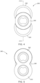
- FIGS. 3 , 4 , 5 , and 6 show top, left, right, and cross-section views, respectively, of the fluid mixing device 240.
- the fluid mixing device 240 has a body defining first and second fluid inlets 242 and 244, each of which is configured to conduct a corresponding one of the first and second injection fluids in a corresponding first and second direction 248 and 250.
- the second direction 250 is along a different axis 276 from the first direction 248.
- the axis of the first direction 248 and the axis of the second direction 250 may be substantially parallel.
- the axis of the first direction 248 may be angled at an acute or an obtuse angle relative to the second direction 250
- first and second redirecting surfaces 252 and 254 are configured to redirect a first fluid and a second fluid entering the first and second fluid inlets 242 and 244, respectively, into the mixing chamber 256 through first and second mixing chamber inlets 270 and 272, where the first and second injection fluids can then be turbulently mixed.
- the first and second injection fluids Prior to entering the mixing chamber 256, the first and second injection fluids independently flow through the first and second fluid inlets 242, 244, respectively.
- the first and second fluids contact the respective first and second redirecting surfaces 252, 254 at distal ends of the first and second fluid inlets 242, 244, respectively.
- the first and second redirecting surfaces 252 and 254 are configured to redirect the first and second injection fluids in a corresponding first and second different direction 258 and 260 that is different than the corresponding first and second directions 248 and 250. Due to this deflection, the first and second injection fluids enter the mixing chamber 256 through first and second mixing chamber inlets 270 and 272 along the corresponding first and second different directions 258 and 260 where the two fluids come into turbulent contact with one another.
- the first and second different directions 258 and 260 are selected so that the first and second injection fluids contact a third redirecting surface 262 at a proximal end of the mixing chamber 256 to turbulently mix the first and second injections fluids together in the mixing chamber 256.
- the third redirecting surface 262 may have a concave-shaped end facing the outlet port 246.
- the mixture of the first and second injection fluids exits the fluid mixing device 240 via the outlet port 246 at a distal end of the fluid mixing device 240 in a direction along a third axis 278.
- the third axis 278 may be parallel with one or both of the first and second axes 274, 276. In other embodiments, the third axis 278 may be arranged at an acute or obtuse angle relative to both of the first and second axes 274, 276.
- the first and second fluid inlets 242 and 244 each have corresponding first and second inlet ports 264 and 266, configured to respectively attach to a first fluid tubing and a second fluid tubing (shown in FIG. 2 ).
- the first fluid tubing and the second fluid tubing may be removably or non-removably connectable to the first and second inlet ports 264, 266.
- the first fluid tubing and the second fluid tubing may be connected to the first and second inlet ports 264, 266 by solvent bonding, laser welding, or other attachment means.
- the first and second redirecting surfaces 252 and 254 are positioned distally relative to the first and second inlet ports 264 and 266, respectively, and the third redirecting surface 262 is positioned proximally relative to the outlet port 246, and the first and second redirecting surfaces 252 and 254.
- the first and second redirecting surfaces 252 and 254 are positioned closer to the outlet port 246 compared to the position of the than the third redirecting surface 262 and the outlet port 246.
- first and second redirecting surfaces 252 and 254 may be formed at a distal end of the corresponding first and second fluid inlets 242 and 244, and each of the first and second redirecting surfaces 252 and 254 at least partially face the corresponding first and second mixing chamber inlets 270 and 272 to the mixing chamber 256, respectively.
- At least one of the first and second redirecting surfaces 252 and 254 may have a concave surface. Concave surface configuration may improve the redirecting nature of the surface with turbulent flow while eliminating corners in which air bubbles may collect or be temporarily suspended during a priming operation.
- each of the first and second redirecting surfaces 252 and 254 may have a radius of curvature greater than or equal to 90°, and in other embodiments being greater than or equal to 150°.
- each of the first and second redirecting surfaces 252 and 254 may have a radius of curvature of from 80° to 160°.
- each of the first and second redirecting surfaces 252 and 254 may have a radius of curvature between 90° and 180°. Accordingly, the injection fluid from each of the inlet lines 217a and 217b contacts the radiused redirecting surfaces 252 and 254, which causes the first and second injection fluids to change the flow direction.
- the radiused redirecting surfaces 252 and 254 may change the flow direction of the first and second injection fluids, respectively, by an angle ranging from 90° to 150° toward different directions 258 and 260 and into the mixing chamber 256. As such, the fluids double back and interact with each other, e.g., turbulently mix, in the mixing chamber 256 in combination with further redirection by the third redirecting surface 262.
- the third redirecting surface 262 may have a radius of curvature greater than or equal to 90°, more preferably being greater than or equal to 150°. In some embodiments, the third redirecting surface 262 may have a radius of curvature between 90° and 180°.
- mixing devices While known mixing devices (not shown) include some swirling of the injection fluids, various conventional mixing devices may still suffer from a density separation, e.g., higher density fluid spinning to the outside of the lower density fluid, which prevents thorough mixing of the first and second fluids.
- the fluid mixing device 240 by way of contrast, produces a substantially homogeneous mixture of the first and second injection fluids during the turbulent mixing process.
- the first and second redirecting surfaces 252 and 254 may include concave-shaped redirecting surfaces that face directions of flow in the first fluid inlet 242 and the second fluid inlet 244, respectively. Additionally, as shown in FIG. 6 , the first fluid inlet 242, the second fluid inlet 244, and the outlet port 246 all have corresponding axes 274, 276, and 278. In some embodiments, the third axis 278 of the outlet port 246 may be positioned between the first and second axes 274 and 276 of the first and second fluid inlets 242 and 244, respectively.
- the third axis 278 of the outlet port 246 may be positioned above or below the first and second axes 274 and 276 of the first and second fluid inlets 242 and 244, respectively. In other embodiments, the third axis 278 of the outlet port 246 may be coaxial with one of the first and second axes 274 and 276 of the first and second fluid inlets 242 and 244. In other embodiments, the first and second different direction 258 and 260 of the fluids entering the mixing chamber 256 may be angled toward each other with a 0 degree to 90 degree angle so that the first and second fluids directly impact each other and turbulently mix.
- the first injection fluid enters the first fluid inlet 242 and the second injection fluid enters the second fluid inlet 244, each from a corresponding one of the first and second inlet lines 217a and 217b (shown in FIG. 2 ).
- the first and second injection fluids then pass through the respective first and second fluid inlets 242 and 244 until they reach the first and second redirecting surfaces 252 and 254.
- the first injection fluid engages the first redirecting surface 252
- the first fluid is redirected in the direction 258 into the mixing chamber 256.
- the second injection fluid engages the second redirecting surface 254 through first mixing chamber inlet 270, the second fluid is redirected in the direction 260 into the mixing chamber 256.
- the first and second injection fluids by having been redirected into the mixing chamber 256 through the second mixing chamber inlet 272, are turbulently mixed together by the flow of the first and second fluids impacting each other and the third redirecting surface 262 in the mixing chamber 256.
- the mixture of the first and second injection fluids is simultaneously engaged with the third redirecting surface 262, upon which time it is redirected through the outlet port 246 and into the outlet line 220, in order to be delivered to the patient or other downstream fluid path component.
- the first and second fluids may be at least partially redirected to flow in opposite directions, such as one flowing in a clockwise direction and the other flowing in a counterclockwise direction in the mixing chamber 256 such that the flow of the first and second fluids engage and impact each other head on to create turbulent mixing.
- the change of inertia associated with the impact of one fluid flowing in a clockwise flow direction and the other fluid flowing in a counterclockwise flow direction results in a turbulently mixed solution of the first and second fluid as the two fluids interact within mixing chamber 256.
- the first and second injection fluids may mix solely in the mixing chamber 256, or in the mixing chamber 256 and in the area of at least one of first redirecting surface 252 and second redirecting surface 254.
- FIG. 7 is a section view of another embodiment of the fluid mixing device 340, according to another example of the present disclosure where at least one of the first fluid inlet 342, the second fluid inlet 344, and the outlet port 346 include a helical "rifling" pattern on an inner surface to further direct and rotate the respective fluid flow in the inlet and/or outlet and increase turbulent mixing of the first and second fluids.
- the pattern may include one or more at least partially helical protrusions or indentations recessed into the inner surface or protruding from the inner surface of at least one of the first fluid inlet 342, the second fluid inlet 344, and the outlet port 346.
- the pattern imparts a rotation of the flow of the fluid within the corresponding fluid path.
- the first fluid inlet 342, the second fluid inlet 344, and the outlet port 346 each have an at least partially helical-shaped portion 343, 345, and 347 for generating a corresponding fluid vortex for at least one of the first injection fluid, the second injection fluid, and the mixture of the first and second injection fluids, respectively, as the respective fluids flow through the channels.
- the helical-shaped portion in one of the inlets or outlet may have directionality (clockwise or counterclockwise) in the same or different direction and may have different dimensions or pitch as the helical-shaped portion in the other portions of the mixing device 340.
- first and second fluid inlets 342 and 344 and the outlet port 346 each have helical-shaped portions 343, 345, and 347, it will be appreciated that any number of the aforementioned regions may be provided with a helical-shaped portion, without departing from the scope of the disclosed concept. By having the helical-shaped portions 343, 345, and 347, mixing may advantageously be further improved. It will be appreciated that the fluid mixing device 340 otherwise functions the same as the fluid mixing device 240 discussed above.
- the outlet port 446 of the fluid mixing device 440 may have one or more baffle members or mixing members 447 located on an interior thereof.
- the baffle member 447 may advantageously further improve mixing of the first and second injection fluids. It will be appreciated that the fluid mixing device 440 otherwise functions the same as the fluid mixing device 240, discussed above.
- the fluid mixing device may include one or more baffle member or mixing member in one or both of the first and second fluid inlets.
- FIG. 9 shows yet a further example of a fluid mixing device 540, in accordance with another embodiment of the present disclosure.
- the fluid mixing device 540 may include a first valve 543 in the first fluid inlet 542 configured to prevent backflow of the second injection fluid into the first fluid inlet 542 and fluid line 217a.
- the fluid mixing device 540 may include a second valve 545 in the second fluid inlet 544 configured to prevent backflow of the first injection fluid into the second fluid inlet 544 and fluid line 217b.
- the fluid mixing device 540 functions the same as the fluid mixing device 240.
- the first direction 648 ( FIG. 12 ) is parallel to, in the opposite direction from, and offset from the second direction 650 ( FIG. 12 ).
- the outlet port 646 of the fluid mixing device 640 has an axis 678 generally perpendicular to the first and second directions 648 and 650.
- the fluid mixing device 640 provides indirect instead of head-on mixing of the two fluids.
- the first direction 648 and the second direction 646 facilitate a direct collision of stream lines of one-half the diameter of the tubing cross-section and indirect mixing of the other one-half of the stream lines. That is, because of the offset of the two opposing fluid directions 648 and 650, half direct mixing and half indirect mixing occurs in the fluid mixing region.
- the first direction 748 is generally perpendicular to the second direction 750.
- the outlet port 746 of the fluid mixing device 740 may have an axis 778 generally parallel and coincidental to an axis 774 of the first fluid inlet 742.
- fluid mixing device 740 (not shown) may have an axis 778 of an outlet port 746 generally parallel and coincidental to an axis of a second fluid inlet 744. At least one notch 745 may be provided between two of the first fluid inlet 742, the second fluid inlet 744, and the outlet port 746.
- the notch 745 may be provided to conserve material in a transition area between two of the first fluid inlet 742, the second fluid inlet 744, and the outlet port 746 to facilitate molding of the fluid mixing device 740.
- the perpendicular collision of the flow paths of the first fluid and the second fluid in the fluid mixing device 740 may create turbulent mixing of the two fluids and limit and/or disrupt any laminar flow of one fluid relative to the other fluid.
- the first direction 848 may be at an angle of between 130° and 165° with respect to the second direction 850.
- the outlet port 846 of the fluid mixing device 840 may have an axis 878 at an angle less than 70° with respect to the first direction 848.
- fluid mixing device 840 (not shown), the outlet port 846 may have an axis 878 at an angle less than 70° with respect to second direction 850.
- the angled but substantially opposite flow of the flow paths of the first fluid and the second fluid in fluid mixing device 840 may create turbulent mixing of the two fluids and limit and/or disrupt any laminar flow of one fluid relative to the other fluid.
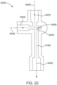
- fluid mixing devices 940A, 940B , and 940C are shown in FIGS. 19-21 .
- the fluid mixing device 940A , 940B , and 940C has a T-shaped 90 degree connector design having one or more offset fluid paths to enhance mixing of the first fluid and the second fluid.
- fluid mixing device 940A includes a first fluid inlet 942A and a second fluid inlet 944A for a first fluid a second fluid respectively, and a fluid outlet 946A. As can be seen in FIG.
- the first fluid flow axis 948A is offset from both the second fluid flow axis 950A and the fluid outlet flow axis 978A.
- Fluid mixing occurs at least in fluid mixing region 980A where offset fluid flow lines of the first fluid along axis 948A interact with fluid flow lines of the second fluid line along axis 950A to create a turbulent mixing in fluid mixing region 980A, which may be further enhanced by the offset of the outlet flow axis 978A to the fluid outlet 946A.
- fluid mixing device 940B includes a first fluid inlet 942B and a second fluid inlet 944B for a first fluid and a second fluid respectively, and a fluid outlet 946B.
- the fluid mixing device 940B also includes a turbulent fluid mixing chamber 956B where further turbulent mixing may occur.
- the first fluid flow axis 948B is offset from both the second fluid flow axis 950B and the fluid outlet flow axis 978B.
- Fluid mixing occurs at least in fluid mixing region 980B where the fluid mixing chamber 956B and the offset fluid flow lines of the first fluid along axis 948B interact with fluid flow lines of the second fluid line along axis 950B to create a turbulent mixing in fluid mixing region 980B, which may be further enhanced by the offset of the outlet flow axis 978B to fluid outlet 946B.
- fluid mixing device 940C includes a first fluid inlet 942C and a second fluid inlet 944C for a first fluid and a second fluid respectively, and a fluid outlet 946C.
- the fluid mixing device 940C also includes a turbulent fluid mixing chamber 956C where further turbulent mixing may occur.
- the first fluid flow axis 948C is offset from and the fluid outlet flow axis 978C, particularly on the side of the flow path opposite the second fluid inlet 944C.
- Fluid mixing occurs at least in fluid mixing region 980C where the fluid mixing chamber 956C and the fluid flow lines of the first fluid along axis 948C interact with fluid flow lines of the second fluid line along axis 950C to create a turbulent mixing in fluid mixing region 980C, which may be further enhanced by the offset of the outlet flow axis 978C to the fluid outlet 946C.
- FIG. 22 is a perspective view of a fluid mixing device 1040 according to some non-limiting embodiments of the present disclosure.
- the fluid mixing device 1040 may be used as part of a fluid delivery tube set, such as the fluid delivery tube set 202 shown in FIG. 2 , wherein the fluid mixing device 1040 is connected to a pair of fluid inlet lines and an outlet line.
- the fluid mixing device 1040 has a body defining first and second fluid inlets 1042 and 1044, each of which is configured to conduct a corresponding one of the first and second injection fluids.
- the fluid mixing device 1040 further has an outlet port 1046 that is configured for delivering a mixture of the first and second injection fluids from the fluid mixing device 1040 to the patient or other downstream fluid path component.
- the fluid mixing device 1040 has a body 1041with a first portion 1043 and a second portion 1045.
- the first portion 1043 and the second portion 1045 may be manufactured separately and are connected together to form the body 1041 of the fluid mixing device 1040.
- the first portion 1043 and the second portion 1045 are connected together in a non-removable manner, such as by adhesive, welding (e.g., laser welding or ultrasonic welding), friction fit, solvent gluing, or other non-removable connection mechanism.
- the first portion 1043 and the second portion 1045 may be removably connected together.
- the first portion 1043 defines a portion of the first and second fluid inlets 1042 and 1044, and has a receiving cavity 1047 for receiving a check valve 1049 in each of the first and second fluid inlets 1042 and 1044.
- the second portion 1045 has a corresponding inner cavity 1051 (shown in FIG. 24A ) that is configured to receive the first portion 1043, including the check valves 1049.
- a second part of the first and second fluid inlets 1042 and 1044 is defined by the inner cavity 1051 of the second portion 1045 (shown in FIGS. 24A-24B ).
- Each check valve 1049 may be configured to prevent backflow of the first and second injection fluids during injection procedures where fluid pressures in the respective first and second tubes delivering the first and second injection fluids to the fluid mixing device 1040 are not equal.
- the check valves 1049 may be made from a compressible material, such as an elastomeric polymer, that may be compressed under the pressurized flow of the fluid from an expanded state to a compressed state.
- the compressible material may be selected as appropriate to provide the appropriate stiffness so that the check valve opens at a selected fluid pressure.
- the check valves 1049 may also be used to isolate the fluid injector system from dampening a hemodynamic blood pressure signal, as discussed herein with reference to FIGS. 28-30 .
- the check valves 1049 may be used to isolate contamination from patient to patient when the fluid mixing device 1040 is configured for multi-patient use. Furthermore, the check valves 1049 prevent "dribbling" of the first and second injection fluids to the outlet after the injection of first and second injection fluids ceases, such as due to release of built-up capacitance or "swelling" of the fluid injector components under pressure.
- FIGS. 24A-24B which show a cross-sectional plan view of the fluid mixing device 1040 taken along line F - F shown in FIG. 22 , the check valves 1049 are shown positioned in the receiving cavity 1047 of each of the first and second fluid inlets 1042 and 1044 of the first portion 1043.
- the receiving cavity 1047 for each valve 1049 is aligned with a direction of fluid flow through each of the first and second fluid inlets 1042 and 1044.
- Each check valve 1049 has a proximal end 1053 that is configured to be in contact with a corresponding sealing face 1055 on the first and second fluid inlets 1042 and 1044 in the first portion 1043 when the check valve 1049 is in a closed position ( FIG.
- Each check valve 1049 further has a distal end 1057 that is engaged with a stop element 1059 positioned within each of the first and second fluid inlets 1042 and 1044.
- each stop element 1059 may be a support structure that is connected to an inner sidewall of the respective first and second fluid inlet 1042, 1044 downstream of the check valve 1049 and is configured to prevent movement of the distal end 1057 of the check valve 1049, thus allowing the check valve 1049 to compress when subject to a pressure force on the proximal end 1053.
- each stop element 1059 may have a pointed proximal end 1071 that is configured to reduce the contact area with the check valve 1049, thereby allowing for a greater compression of the check valve 1049 between its proximal and distal ends 1053 and 1057 at a lower fluid pressure.
- the distal end 1057 may compress and mold around the pointed proximal end 1061 of the stop element 1059 allowing the outer circumference of the proximal end 1053 to more readily release from the sealing face 1055.
- the pointed stop element 1059 allows for decreased pressure drops by allowing easier opening during injections compared to stop elements with a flat supporting surface.
- stop element 1059 is made from a silicone material.
- the first and second injection fluids are urged under pressure through the first and second fluid inlets 1042 and 1044 such that the first and second fluids engage respective proximal ends 1053 of the check valves 1049.
- the proximal ends 1053 engage the sealing face 1055 on the first portion 1043 ( FIG. 24A ) to block the passage of the first and second injection fluids past the check valve 1049.
- the force on the proximal end 1053 of the check valves 1049 increases.
- each check valve 1049 Due to the compressible nature of each check valve 1049, the proximal end 1053 is urged in the distal direction, thereby creating a gap between the proximal end 1053 of the check valves 1049 and the sealing face 1055 on the first portion 1043. As shown in FIG. 24B , such a gap is formed only when sufficient fluid pressure P is imparted on the proximal end 1053, such as, for example, during atypical injection procedure. The pressurized first and second injection fluids then travel around the respective check valves 1049 and through the fluid mixing device 1040, as described herein.
- each check valve 1049 in the fluid inlet with the lower pressure may close to prevent a backflow of the fluid in an upstream direction, for example due to the back pressure of the higher pressure fluid on the distal end 1055 of the lower pressure check valve 1049.
- the resilient nature of each check valve 1049 causes the check valve 1049 to expand axially such that the proximal end 1053 engages the sealing face 1055 on the first portion 1043 to prevent additional fluid from flowing past the check valve 1049. In this manner, any excess fluid is prevented from flowing through the fluid mixing device 1040 after the completion of the injection procedure. Further, any backflow of one fluid into the other fluid path is prevented.
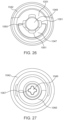
- each check valve 1049 is dimensioned such that its outer diameter is slightly smaller than an inner diameter of a channel 1060 defined by the receiving cavity 1047 of the first portion 1043 (shown in FIGS. 23A- 24B ) and the corresponding inner cavity 1051 of the second portion 1045 of the body 1043 (shown in FIG. 26 ).
- fluid may pass around the body of each check valve 1049 and through the channel 1060.
- the channel 1060 may have a non-circular cross-section and the check valve 1049 may have a circular cross-section. In this manner, the channel 1060 defines a flow path for the first and second injection fluids to flow around the respective check valves 1049, when the check valve 1049 is in the open position.
- the channel 1060 may have a fluted cross-section with one or more flutes 1061.
- the flutes 1061 may be spaced apart from each other at equal or unequal spacing about a perimeter of the channel 1060.
- the number of flutes 1061, the radial depth, and/or the circumferential width of the flutes 1061 may be selected based on a desired flow rate of the first and second fluids through the channel 1061 when the respective check valves 1049 are in the open position.
- Each check valve 1049 is desirably an elastomeric part that is at least partially compressible in a longitudinal direction when acted upon by fluid pressure.
- the check valve 1049 in the first fluid inlet 1042 may be the same or different compared to the check valve 1049 in the second fluid inlet 1044.
- the opening pressure of each check valve 1049 may be selected based on the characteristics of the fluid injector, and/or the characteristics of the first and second injection fluids, such as the fluid viscosity, and the temperature range, flow rate range, and the pressure range at which the first and second injections fluids will be injected.
- an inlet opening 1065 surrounding the sealing face 1055 may have a shape that corresponds to the shape of the channel 1060 (shown in FIG. 25 ).
- the inlet opening 1065 may have a taper 1067 that tapers radially inward in a direction from the proximal end toward the distal end of the fluid mixing device 1040.
- the cross-sectional shape of the inlet opening 1065 is chosen to achieve a low pressure drop and a lower opening pressure for the check valve 1049.
- the fluid mixing device 1040 creates turbulent mixing of the first and second fluids similar to the fluid mixing device 240, discussed herein.
- the first and second fluid inlets 1042 and 1044 have corresponding first and second redirecting surfaces 1052 and 1054.
- the fluid mixing device 1040 further has a mixing chamber 1056 in fluid communication with the first and second fluid inlets 1042 and 1044 and an outlet port 1046 in fluid communication with the mixing chamber 1056.
- the mixing chamber 1056 is configured to turbulently mix the first and second injection fluids together.
- the first and second redirecting surfaces 1052 and 1054 are configured to redirect a first fluid and a second fluid entering the first and second fluid inlets 1042 and 1044, respectively, into the mixing chamber 1056, where the first and second injection fluids can then be turbulently mixed.
- the first and second redirecting surfaces 1052 and 1054 are configured to redirect the first and second injection fluids in a corresponding first and second different directions that are different than the corresponding first and second directions in which the first and second injection fluids flow prior to contacting the first and second redirecting surfaces 1052 and 1054.
- the first and second injection fluids enter the mixing chamber 1056 along the corresponding first and second different directions and contact a third redirecting surface 1062 at a proximal end of the mixing chamber 1056 to turbulently mix the first and second injections fluids together in the mixing chamber 1056.
- the mixture of the first and second injection fluids exits the fluid mixing device 1040 via the outlet port 1046 at a distal end of the fluid mixing device 1040.
- the outlet port 1046 may have a connection element 1070 configured for permitting removable connection of the outlet port 1046 with outlet tubing, such as the outlet line 220 shown in FIG. 2 .
- the connection element 1070 may be a male luer lock that is configured to removably connect with a corresponding female luer lock on the proximal end of the outlet line 220.
- the connection element 1070 may be a female luer lock that is configured to removably connect with a corresponding male luer lock on the proximal end of the outlet line 220.
- fluid path connectors such as described in International PCT Application Nos. PCT/US2021/018523 and PCT/US2016/063448 .
- the fluid mixing device 1040 can be removably connected to an outlet line 220 to thereby permit the use of the fluid mixing device 1040 with multiple patients, for example if one or more check valves are attached upstream of the connector on the outlet port 1046.
- a fluid mixing device 1140 having a body 1141 defining first and second fluid inlets 1142 and 1144, each of which is configured to conduct a corresponding one of the first and second injection fluids.
- the body of the fluid mixing device 1140 further includes an outlet port 1146 configured for delivering a mixture of the first and second injection fluids to outlet tubing (not shown).
- the body 1141 with a first portion 1143 and a second portion 1145 that are non-removably or removably connected together.
- a check valve 1149 is disposed in a channel 1155 of each of the first and second fluid inlets 1142 and 1144 (shown in FIG.
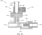
- FIGS. 28- 30 The structure and functionality of the fluid mixing device 1140 shown in FIGS. 28- 30 is substantially identical to the structure and functionality of the fluid mixing device 1040 described herein with reference to FIGS. 22-27 . Accordingly, only the relative differences between the two embodiments will now be discussed.
- the outlet port 1146 may have a pressure isolation valve 1150 configured to allow for connecting a pressure transducer to the fluid path so that hemodynamic blood pressure signal readings may be obtained during fluid delivery.
- the pressure isolation valve 1150 isolates the high pressure fluid injector system from interfering with a low pressure measurement of a hemodynamic blood pressure signal.
- the pressure isolation valve 1150 includes a housing 1152, which may be a unitary structure or, preferably, a multi-piece structure as shown in FIG. 29 .
- the housing 1152 is a two-piece housing including a first portion 1152a and a second portion 1152b, which are adapted to connect together to form the housing 1150.
- the first and second portions 1152a, 1152b are preferably formed for non-removable engagement with each other.
- suitable pressure isolation valves are described in U.S. Patent Nos. 6,866,654 ; 7,611,503 ; 8,919,384 ; and 8,992,489 , the disclosures of which are incorporated by reference.
- the first portion 1152a of the housing 1152 defines a high pressure lumen 1154, which forms a high pressure side of the pressure isolation valve 1150.
- the high-pressure lumen 1154 is in fluid communication with the outlet port 1146.
- the second portion 1152b of the housing 1152 defines a low pressure lumen 1156, which generally forms a low pressure side of the pressure isolation valve 1150.
- the second portion 1152b of the housing 1152 further includes a pressure isolation port 1158 to which a pressure transducer (not shown) may be connected.
- the structure forming pressure isolation port 1158 may terminate in a luer connector or other suitable medical connector for connecting a pressure transducer to the pressure isolation port 1158.
- the first and second portions 1152a, 1152b of the housing 1152 may define an internal chamber 1160 generally in fluid communication with the high pressure lumen 1154 and the low pressure lumen 1156.
- An internal valve member 1162 is located in the internal chamber 1160 and is biased to a normally open position, wherein the high pressure lumen 1154 is in fluid communication with the low pressure lumen 1156.
- the valve member 1162 is generally further adapted to isolate the low pressure lumen 1156 once fluid pressure in the high pressure lumen 1154 reaches a preset pressure.
- the low pressure lumen 1156 further includes a flow initiating port 1164 having a flow initiating valve 1166 that is generally adapted to initiate a small flow around the valve member 1162 such that the valve member 1162 operates to a closed position substantially upon flow initiation.
- fluid mixing devices for mixing two injection fluids
- similar fluid mixing devices with three or even four total fluid inlets, each having corresponding redirecting surfaces, where the fluid inlets are in fluid communication with a mixing chamber similar to as described herein may also be possible.
- Such fluid mixing devices fall within the scope of the present disclosure.
Landscapes
- Health & Medical Sciences (AREA)
- Heart & Thoracic Surgery (AREA)
- Public Health (AREA)
- Veterinary Medicine (AREA)
- Anesthesiology (AREA)
- Biomedical Technology (AREA)
- Hematology (AREA)
- Life Sciences & Earth Sciences (AREA)
- Animal Behavior & Ethology (AREA)
- General Health & Medical Sciences (AREA)
- Engineering & Computer Science (AREA)
- Pulmonology (AREA)
- Chemical & Material Sciences (AREA)
- Vascular Medicine (AREA)
- Chemical Kinetics & Catalysis (AREA)
- Dispersion Chemistry (AREA)
- Infusion, Injection, And Reservoir Apparatuses (AREA)
- Injection Moulding Of Plastics Or The Like (AREA)
- Liquid Crystal Substances (AREA)
- Accessories For Mixers (AREA)
- Processing And Handling Of Plastics And Other Materials For Molding In General (AREA)
Claims (14)
- Dispositif de mélangeage de fluides (240) pour le mélangeage d'un premier fluide d'injection (F1) et d'un second fluide d'injection (F2), le dispositif de mélangeage de fluides (240) comprenant :une première entrée de fluide,une seconde entrée de fluide,une chambre de mélangeage, etun orifice de sortie,caractérisé en ce quela première entrée de fluide (242) est configurée pour diriger le premier fluide d'injection (F1) dans une première direction (248) le long d'un premier axe (274) vers une première surface de réorientation concave (252), la première entrée de fluide (242) ayant une première surface de réorientation (252) ;la seconde entrée de fluide (244) est configurée pour diriger le second fluide d'injection (F2) dans une seconde direction (250) le long d'un deuxième axe (276) différent du premier axe (274) et vers une deuxième surface de réorientation concave (254), la seconde entrée de fluide (244) ayant la deuxième surface de réorientation (254), dans lequel le premier axe (274) de la première direction (248) et le deuxième axe (276) de la seconde direction (250) sont sensiblement parallèles ;la chambre de mélangeage (256) est en communication fluidique avec la première entrée de fluide (242) et la seconde entrée de fluide (244) et a une troisième surface de réorientation concave (262) à l'extrémité proximale de la chambre de mélangeage, la chambre de mélangeage (256) est configurée pour mélanger le premier fluide d'injection (F1) et le second fluide d'injection (F2) ; etl'orifice de sortie (246) est à une extrémité distale du dispositif de mélangeage de fluides (240) et en communication fluidique avec la chambre de mélangeage (256) et distale à la première entrée de fluide (242) et à la seconde entrée de fluide (244),dans lequel la première entrée de fluide (242) et la seconde entrée de fluide (244) ont un premier orifice d'entrée (264) et un second orifice d'entrée (266), respectivement, dans lequel la première surface de réorientation (252) et la deuxième surface de réorientation (254) sont positionnées distalement relativement au premier orifice d'entrée (264) et au second orifice d'entrée (266), respectivement, et dans lequel la troisième surface de réorientation (262) est positionnée proximalement relativement à l'orifice de sortie (246), à la première surface de réorientation (252), et à la deuxième surface de réorientation (254),dans lequel la première surface de réorientation (252) est configurée pour réorienter le premier fluide d'injection (F1) dans une première direction différente (258), par rapport à la première direction (248), pour entrer dans la chambre de mélangeage (256) le long de la première direction différente (258), et la deuxième surface de réorientation (254) est configurée pour réorienter le second fluide d'injection (F2) dans une seconde direction différente (260), par rapport à la seconde direction (250), pour entrer dans la chambre de mélangeage (256) le long de la seconde direction différente (260), dans lequel la première direction différente (258) et la seconde direction différente (260) sont sélectionnées de telle sorte que le premier fluide d'injection (F1) et le second fluide d'injection (F2) entrent en contact avec la troisième surface de réorientation (262) de la chambre de mélangeage (256) pour mélanger de façon turbulente le premier fluide d'injection (F1) et le second fluide d'injection (F2) dans la chambre de mélangeage (256), etdans lequel un mélange du premier fluide d'injection (F1) et du second fluide d'injection (F2) sort du dispositif de mélangeage de fluides (240) à travers l'orifice de sortie (246) dans une direction le long d'un troisième axe (278), dans lequel le troisième axe (278) est sensiblement parallèle au premier axe (274) et au deuxième axe (276).
- Dispositif de mélangeage de fluides (240) de la revendication 1, comprenant en outre au moins une d'une première soupape de non-retour (1049) dans la première entrée de fluide (242) ; et d'une seconde soupape de non-retour (1049) dans la seconde entrée de fluide (244).
- Dispositif de mélangeage de fluides (240) de la revendication 1 ou 2, dans lequel la chambre de mélangeage (256) comprend en outre une première entrée (270), dans lequel la première entrée (270) de la chambre de mélangeage (256) est distale à la troisième surface de réorientation (262), et dans lequel la première surface de réorientation (252) est positionnée distalement à la première entrée de fluide (242) et fait au moins partiellement face à la première entrée (270) donnant sur la chambre de mélangeage (256).
- Dispositif de mélangeage de fluides (240) de l'une quelconque des revendications 1 à 3, dans lequel la chambre de mélangeage (256) comprend en outre une seconde entrée (272), dans lequel la seconde entrée (272) de la chambre de mélangeage (256) est distale à la troisième surface de réorientation (262), et dans lequel la deuxième surface de réorientation (254) est positionnée distalement à la seconde entrée de fluide (244) et fait au moins partiellement face à la seconde entrée (272) donnant sur la chambre de mélangeage (256).
- Dispositif de mélangeage de fluides (240) de l'une quelconque des revendications 1 à 4, dans lequel au moins une de la première surface de réorientation (252) et de la deuxième surface de réorientation (254) a un rayon de courbure supérieur ou égal à 90 °, de préférence dans lequel au moins une de la première surface de réorientation (252) et de la deuxième surface de réorientation (254) a un rayon de courbure supérieur ou égal à 150 °.
- Dispositif de mélangeage de fluides (240) de quelconques des revendications 1 à 5, dans lequel la troisième surface de réorientation de forme sensiblement concave fait face à l'orifice de sortie (246).
- Dispositif de mélangeage de fluides (240) de la revendication 6, dans lequel la surface de forme concave de la troisième surface de réorientation (262) a un rayon de courbure supérieur ou égal à 90 °, de préférence dans lequel la surface de forme concave a un rayon de courbure supérieur ou égal à 150 °.
- Dispositif de mélangeage de fluides (240) de l'une quelconque des revendications 2 à 7, dans lequel la première soupape de non-retour (1049) a une première extrémité (1053) en prise avec un premier orifice d'entrée (264) sur la première entrée de fluide (1042) et une seconde extrémité (1057) en prise avec un premier élément de butée (1059) proximal à la première surface de réorientation (1052), dans lequel la seconde soupape de non-retour (1049) a une première extrémité (1053) en prise avec un second orifice d'entrée (266) sur la seconde entrée de fluide (1044) et une seconde extrémité (1057) en prise avec un second élément de butée (1059) proximal à la deuxième surface de réorientation (1054), et dans lequel la première soupape de non-retour (1049) et la seconde soupape de non-retour (1049) sont réversiblement compressibles entre la première extrémité (1053) et la seconde extrémité (1057) en réponse à une première pression de fluide du premier fluide d'injection (F1) s'écoulant à travers le premier orifice d'entrée (264) et à une seconde pression de fluide du second fluide d'injection (F2) s'écoulant à travers le second orifice de fluide (266), respectivement, de préférence dans lequel le premier élément de butée (1059) et le second élément de butée (1059) ont chacun une extrémité proximale pointue (1071).
- Dispositif de mélangeage de fluides (240) de l'une quelconque des revendications 1 à 8, dans lequel l'orifice de sortie (246) a un axe (278) parallèle à un axe de la première direction (248) de la première entrée de fluide (242) et à un axe de la seconde direction (250) de la seconde entrée de fluide (244), de préférence dans lequel l'axe (278) de l'orifice de sortie (246) s'étend entre l'axe de la première direction (248) de la première entrée de fluide (242) et l'axe de la seconde direction (250) de la seconde entrée de fluide (244).
- Dispositif de mélangeage de fluides (240) de l'une quelconque des revendications 1 à 9, dans lequel chacune de la première surface de réorientation (252) et de la deuxième surface de réorientation (254) est de forme concave et fait face à la première direction d'écoulement de fluide (248) du premier fluide d'injection (F1) dans la première entrée de fluide (242) et à la seconde direction d'écoulement de fluide (250) du second fluide d'injection (F2) dans la seconde entrée de fluide (244), respectivement.
- Dispositif de mélangeage de fluides (240) de l'une quelconque des revendications 1 à 10, dans lequel au moins un de la première entrée de fluide (242), de la seconde entrée de fluide (244), et de l'orifice de sortie (246) a une rayure au moins partiellement hélicoïdale (343, 345, 347) sur au moins une partie d'une surface intérieure de l'au moins un de la première entrée de fluide (242), de la seconde entrée de fluide (244), et de l'orifice de sortie (246) afin de créer un tourbillon de fluide correspondant pour au moins un du premier fluide d'injection (F1), du second fluide d'injection (F2), et du mélange du premier fluide d'injection (F1) et du second fluide d'injection (F2).
- Dispositif de mélangeage de fluides (240) de l'une quelconque des revendications 1 à 11, dans lequel l'orifice de sortie (246) comprend en outre une soupape d'isolement de pression (1150) intégrée avec celui-ci.
- Dispositif de mélangeage de fluides (240) de la revendication 12, dans lequel la soupape d'isolement de pression (1150) comprend un logement (1152) ayant une première lumière (1154) en communication fluidique avec l'orifice de sortie (246), une seconde lumière (1156) configurée pour le raccordement à un transducteur de pression, et un organe de soupape (1162) entre la première lumière (1154) et la seconde lumière (1156), dans lequel l'organe de soupape (1162) est configuré pour l'isolement de la seconde lumière (1156) par rapport à l'orifice de sortie (246) durant une procédure d'injection de fluide.
- Ensemble de tubes d'administration de fluide (202) pour l'administration de fluide depuis un injecteur de fluide (100) à un patient, l'ensemble de tubes d'administration de fluide (202) comprenant :un premier tube d'entrée (217a) configuré pour administrer le premier fluide d'injection (F1) ;un second tube d'entrée (217b) configuré pour administrer le second fluide d'injection (F2) ;un tube de sortie (220) configuré pour administrer un mélange du premier fluide d'injection (F1) et du second fluide d'injection (F2) au patient ; etle dispositif de mélangeage de fluides (240) selon l'une quelconque des revendications 1 à 13.
Priority Applications (4)
| Application Number | Priority Date | Filing Date | Title |
|---|---|---|---|
| HRP20241714TT HRP20241714T1 (hr) | 2020-02-28 | 2021-02-25 | Komplet za miješanje fluida |
| SI202130257T SI4110452T1 (sl) | 2020-02-28 | 2021-02-25 | Komplet za mešanje tekočin |
| RS20250035A RS66407B1 (sr) | 2020-02-28 | 2021-02-25 | Komplet za mešanje tečnosti |
| EP24199121.5A EP4537889A3 (fr) | 2020-02-28 | 2021-02-25 | Set de melange de fluid |
Applications Claiming Priority (2)
| Application Number | Priority Date | Filing Date | Title |
|---|---|---|---|
| US202062982995P | 2020-02-28 | 2020-02-28 | |
| PCT/US2021/019507 WO2021173743A1 (fr) | 2020-02-28 | 2021-02-25 | Ensemble de mélange de fluide |
Related Child Applications (2)
| Application Number | Title | Priority Date | Filing Date |
|---|---|---|---|
| EP24199121.5A Division-Into EP4537889A3 (fr) | 2020-02-28 | 2021-02-25 | Set de melange de fluid |
| EP24199121.5A Division EP4537889A3 (fr) | 2020-02-28 | 2021-02-25 | Set de melange de fluid |
Publications (2)
| Publication Number | Publication Date |
|---|---|
| EP4110452A1 EP4110452A1 (fr) | 2023-01-04 |
| EP4110452B1 true EP4110452B1 (fr) | 2024-10-16 |
Family
ID=75108820
Family Applications (2)
| Application Number | Title | Priority Date | Filing Date |
|---|---|---|---|
| EP21713224.0A Active EP4110452B1 (fr) | 2020-02-28 | 2021-02-25 | Set de mélange de fluid |
| EP24199121.5A Pending EP4537889A3 (fr) | 2020-02-28 | 2021-02-25 | Set de melange de fluid |
Family Applications After (1)
| Application Number | Title | Priority Date | Filing Date |
|---|---|---|---|
| EP24199121.5A Pending EP4537889A3 (fr) | 2020-02-28 | 2021-02-25 | Set de melange de fluid |
Country Status (26)
| Country | Link |
|---|---|
| US (3) | US11712552B2 (fr) |
| EP (2) | EP4110452B1 (fr) |
| JP (2) | JP7684324B2 (fr) |
| KR (2) | KR102882030B1 (fr) |
| CN (2) | CN115175726B (fr) |
| AU (2) | AU2021227677B2 (fr) |
| CA (1) | CA3173295A1 (fr) |
| CL (1) | CL2022002331A1 (fr) |
| CO (1) | CO2022011741A2 (fr) |
| CR (1) | CR20220391A (fr) |
| DK (1) | DK4110452T3 (fr) |
| ES (1) | ES3003561T3 (fr) |
| FI (1) | FI4110452T3 (fr) |
| HR (1) | HRP20241714T1 (fr) |
| HU (1) | HUE069993T2 (fr) |
| IL (1) | IL295599B2 (fr) |
| LT (1) | LT4110452T (fr) |
| MX (2) | MX2022010694A (fr) |
| NZ (1) | NZ791617A (fr) |
| PH (1) | PH12022552286A1 (fr) |
| PL (1) | PL4110452T3 (fr) |
| PT (1) | PT4110452T (fr) |
| RS (1) | RS66407B1 (fr) |
| SI (1) | SI4110452T1 (fr) |
| WO (1) | WO2021173743A1 (fr) |
| ZA (1) | ZA202409850B (fr) |
Families Citing this family (14)
| Publication number | Priority date | Publication date | Assignee | Title |
|---|---|---|---|---|
| WO2021168076A1 (fr) | 2020-02-21 | 2021-08-26 | Bayer Healthcare Llc | Raccords de trajet de fluide permettant l'administration de fluide médical |
| MX2022010694A (es) | 2020-02-28 | 2022-09-26 | Bayer Healthcare Llc | Juego de mezcla de fluidos. |
| US12427247B2 (en) | 2020-03-16 | 2025-09-30 | Bayer Healthcare Llc | Stopcock apparatus for angiography injector fluid paths |
| CN115697435B (zh) | 2020-06-18 | 2026-03-03 | 拜耳医药保健有限责任公司 | 用于血管造影注入器流体路径的在线气泡悬浮装置 |
| EP4168065A1 (fr) | 2020-06-18 | 2023-04-26 | Bayer HealthCare, LLC | Système et procédé pour un enclenchement de piston de seringue avec un injecteur |
| HRP20250659T1 (hr) | 2020-08-11 | 2025-08-01 | Bayer Healthcare Llc | Značajke angiografske štrcaljke |
| CN116547022A (zh) | 2020-12-01 | 2023-08-04 | 拜耳医药保健有限责任公司 | 用于保持流体注入器系统的流体路径部件的盒 |
| EP4088758A1 (fr) * | 2021-05-12 | 2022-11-16 | Fresenius Medical Care Deutschland GmbH | Site de perfusion d'un système de tubulures sanguines |
| JP7670866B2 (ja) | 2021-06-17 | 2025-04-30 | バイエル・ヘルスケア・エルエルシー | 流体注入器装置用のチュービング内の流体タイプを検出するためのシステムおよび方法 |
| AU2023263999A1 (en) | 2022-05-04 | 2024-10-31 | Bayer Healthcare Llc | System, method, and computer program product for guided workflow features for operating a fluid injector system |
| WO2023244580A1 (fr) | 2022-06-14 | 2023-12-21 | Bayer Healthcare Llc | Capuchon de désinfection pour élément trajet de fluide |
| JP2025534080A (ja) | 2022-10-18 | 2025-10-09 | バイエル・ヘルスケア・エルエルシー | 流体インジェクタのチューブセットのための圧力解放アセンブリ |
| WO2024263922A2 (fr) * | 2023-06-23 | 2024-12-26 | The Methodist Hospital | Connecteur à lumières multiples |
| AU2024382435A1 (en) | 2023-11-17 | 2026-05-07 | Bayer Healthcare Llc | System and method for sensing presence of injector pressure jacket |
Citations (1)
| Publication number | Priority date | Publication date | Assignee | Title |
|---|---|---|---|---|
| US3868967A (en) * | 1973-02-16 | 1975-03-04 | Shropshire Kenneth W | Adapter for mixing fluids |
Family Cites Families (398)
| Publication number | Priority date | Publication date | Assignee | Title |
|---|---|---|---|---|
| US508584A (en) | 1893-11-14 | Device for mixing hot and gold water for bathing | ||
| US352715A (en) | 1886-11-16 | Clock-movement frame | ||
| US798093A (en) | 1904-05-11 | 1905-08-29 | Edward F Dean | Hypodermic syringe. |
| US817054A (en) | 1904-11-10 | 1906-04-03 | James W Lynd | Syringe. |
| US937029A (en) | 1907-10-30 | 1909-10-12 | Blessing B Strong | Means for hypodermic medication. |
| US945143A (en) | 1909-07-28 | 1910-01-04 | Iacques Szamek | Apparatus for mixing liquids. |
| US1388946A (en) | 1920-05-18 | 1921-08-30 | Semi Unit Corp | Hypodermic syringe |
| US1930929A (en) | 1931-05-12 | 1933-10-17 | Eisenberg Moses Joel | Hypodermic implement |
| US2062285A (en) | 1934-05-02 | 1936-12-01 | Bergman Sam | Syringe |
| US2514575A (en) | 1945-02-17 | 1950-07-11 | Howard T Hein | Introversion syringe |
| US2511291A (en) | 1947-03-12 | 1950-06-13 | Grover C Mueller | Mixer for liquids |
| US2616422A (en) | 1948-10-18 | 1952-11-04 | Jones John Leslie | Vaginal applicator |
| US2592381A (en) | 1949-10-13 | 1952-04-08 | Premo Pharmaceutical Lab Inc | Hypodermic syringe |
| US2583206A (en) | 1949-12-01 | 1952-01-22 | Separator Ab | Apparatus for homogenizing |
| US2690179A (en) | 1950-01-20 | 1954-09-28 | Fox Dorothy Brown | Syringe |
| US2673561A (en) | 1951-03-22 | 1954-03-30 | Jr Charles B Peterson | Disposable double-action syringe |
| US2672866A (en) | 1951-03-31 | 1954-03-23 | Kater Hermann | Medical syringe |
| US2667163A (en) | 1951-10-13 | 1954-01-26 | Arthur E Smith | Unitary syringe |
| US2688963A (en) | 1951-10-13 | 1954-09-14 | Arthur E Smith | Syringe unit |
| US2688964A (en) | 1951-12-26 | 1954-09-14 | Arthur E Smith | Syringe |
| US2667165A (en) | 1952-03-19 | 1954-01-26 | Arthur E Smith | Disposable syringe |
| US2667872A (en) | 1952-03-19 | 1954-02-02 | Arthur E Smith | Syringe unit |
| US2667164A (en) | 1952-03-19 | 1954-01-26 | Arthur E Smith | Syringe |
| US2717598A (en) | 1952-11-21 | 1955-09-13 | Louis R Krasno | Hypodermic syringe |
| BE536964A (fr) | 1954-09-03 | |||
| US2911972A (en) | 1954-09-14 | 1959-11-10 | Elinger Adolfo Scholcoff | Hypodermic syringe-ampulla |
| US2805662A (en) | 1955-02-16 | 1957-09-10 | Becton Dickinson Co | Syringe assembly |
| US2950717A (en) | 1955-03-21 | 1960-08-30 | R K Price Associates Inc | Ampules |
| US2915986A (en) | 1955-05-03 | 1959-12-08 | Doreen Elizabeth Sisson | Hand pump for liquids |
| FR1288915A (fr) | 1961-02-17 | 1962-03-30 | Dispositif de déformation de récipients souples | |
| US3199511A (en) | 1961-04-26 | 1965-08-10 | Kulick George | Apparatus for precise administration of parenteral fluids |
| NL122709C (fr) | 1961-06-13 | |||
| FR1307952A (fr) | 1961-09-12 | 1962-11-03 | Récipient distributeur à fond mobile | |
| US3166070A (en) | 1961-12-05 | 1965-01-19 | Lapis Engineering Company Ltd | Syringe for hypodermic injection |
| US3155281A (en) | 1962-04-09 | 1964-11-03 | Questron America Inc | Container |
| US3159312A (en) | 1962-09-28 | 1964-12-01 | Budd Co | Dispensing device for mixing two viscous fluids |
| US3161195A (en) | 1963-01-29 | 1964-12-15 | American Cyanamid Co | Two-compartment aspirating hypodermic syringe |
| US3161194A (en) | 1963-02-04 | 1964-12-15 | Samuel L Chapman | Hypodermic syringe |
| US3190619A (en) | 1963-05-27 | 1965-06-22 | Union Carbide Corp | Fluid mixing container assembly |
| US3172577A (en) | 1963-07-23 | 1965-03-09 | R E Hartung Company Inc | Pump bottle |
| GB1095316A (en) | 1963-08-08 | 1967-12-13 | Arthur Bane | Improvements in ampoules for surgical hypodermic syringes |
| US3276472A (en) | 1963-12-03 | 1966-10-04 | Medex Inc | Medical valve |
| US3301293A (en) | 1964-12-16 | 1967-01-31 | Owens Illinois Inc | Collapsible container |
| US3353537A (en) | 1965-08-11 | 1967-11-21 | George W Knox | Automatic multi-dosage inoculating instrument |
| SE326083B (fr) * | 1966-02-01 | 1970-07-13 | Shunt Ab Vaermeteknik | |
| GB1175184A (en) | 1966-02-08 | 1969-12-23 | Arthur Bane | Improvements in Syringe Ampoules. |
| CH461034A (fr) | 1966-06-27 | 1968-08-15 | Werding Wienfried | Appareil de transfusion |
| US3411503A (en) | 1966-06-27 | 1968-11-19 | Louis S. Santomieri | Collapsible mixing syringe with extrusion casing |
| US3390821A (en) | 1966-09-28 | 1968-07-02 | Mullan Joseph | Collapsible container |
| US3471058A (en) | 1966-10-06 | 1969-10-07 | Peter A Latham | Collapsible dispensing container |
| US3412906A (en) | 1966-12-05 | 1968-11-26 | Amp Inc | Plasma infusor |
| US3527215A (en) | 1967-02-20 | 1970-09-08 | American Hospital Supply Corp | Syringe construction having internal bladder |
| US3442424A (en) | 1967-08-31 | 1969-05-06 | Rexall Drug Chemical | Multiple compartment collapsible tubes |
| US3474844A (en) | 1967-12-14 | 1969-10-28 | Rudolph O Lindstrom | Latching device for collapsible container |
| US3557788A (en) | 1968-03-08 | 1971-01-26 | Betty J Swartz | Disposable syringe |
| US3506163A (en) | 1968-05-22 | 1970-04-14 | James A Rauh | Article for holding and dispensing flowable materials |
| DE1806461B1 (de) | 1968-10-31 | 1970-03-12 | Otto Berkmueller | Tube od.dgl. hohlzylindrischer Behaelter zur Bevorratung und Abgabe eines fluessigen oder pastoesen Fuellgutes |
| US3618846A (en) | 1969-02-17 | 1971-11-09 | Patrick J Poli | Manually operated suction device |
| BE758739A (fr) | 1969-11-13 | 1971-04-16 | Fuji Photo Film Co Ltd | Procede et appareil en vue de transporter un fluide |
| US3699961A (en) | 1970-03-12 | 1972-10-24 | Sebon Corp The | Syringe and method |
| US3873003A (en) | 1970-07-06 | 1975-03-25 | Mayer & Co Inc O | Dome-bottomed container |
| US3635444A (en) | 1970-09-08 | 1972-01-18 | Amvit | Static mixer |
| US3671208A (en) | 1970-10-09 | 1972-06-20 | Wayne G Medsker | Fluid mixing apparatus |
| US3826409A (en) | 1971-06-25 | 1974-07-30 | E Chilcoate | Liquid dosage dispenser |
| BE792131A (fr) | 1972-02-15 | 1973-03-16 | Sherwood Medical Ind Inc | Dispositifs pour l'injection de medicaments |
| US3785367A (en) | 1972-03-13 | 1974-01-15 | Pharmasel Division American Ho | Arterial blood sampler |
| DE2341400C3 (de) | 1973-08-16 | 1979-01-18 | Frupack-Plastic, Kunststoffverarbeitungswerk Ingeborg Luetten, 2000 Hamburg | Verfahren und Vorrichtung zum Herstellen eines mit vorzugsweise einem flüssigen Medium gefüllten Hohlkörpers |
| US4066080A (en) | 1973-08-20 | 1978-01-03 | Sneider Vincent R | Disposable syringes |
| US3938514A (en) | 1974-07-18 | 1976-02-17 | Boucher Lionel J | Bladder wash method and apparatus |
| US4044836A (en) | 1974-11-19 | 1977-08-30 | Martin Edward J | Axial compression powder dispenser |
| US4140117A (en) | 1975-05-12 | 1979-02-20 | Alza Corporation | Cartridge for liquid infusion apparatus |
| US4041944A (en) | 1975-07-21 | 1977-08-16 | Rhodes William A | Body fluid transfusion and displacement apparatus and method |
| US3998223A (en) | 1975-10-24 | 1976-12-21 | The United States Of America As Represented By The Secretary Of The Navy | Syringe apparatus |
| US4064879A (en) | 1976-04-06 | 1977-12-27 | Metatech Corporation | Pressure-indicating syringe |
| GB1583157A (en) | 1976-05-07 | 1981-01-21 | Kenova Ab | Syringes |
| US4131217A (en) | 1977-05-19 | 1978-12-26 | Landstingens Inkopscentral, L I C | Device for emptying a container |
| US4171698A (en) | 1977-08-15 | 1979-10-23 | Abbott Laboratories | Prefilled two-compartment syringe |
| US4136802A (en) | 1977-09-21 | 1979-01-30 | The Continental Group, Inc. | Spray dispenser with spring biased flexible container |
| US4329067A (en) | 1978-04-19 | 1982-05-11 | Bruce J. Landis | Fluid mixer |
| US4204775A (en) | 1978-08-08 | 1980-05-27 | General Dynamics Corporation Pomona Division | Mixing device for simultaneously dispensing two-part liquid compounds from packaging kit |
| US4208136A (en) | 1978-12-01 | 1980-06-17 | Komax Systems, Inc. | Static mixing apparatus |
| US4245655A (en) | 1979-07-05 | 1981-01-20 | The Kendall Company | Blood collection device |
| US4349129A (en) | 1979-12-03 | 1982-09-14 | The Procter & Gamble Company | Portable, measured volume dispenser |
| US4318400A (en) | 1980-01-18 | 1982-03-09 | Alza Corporation | Medical infusor |
| US4312344A (en) | 1980-04-03 | 1982-01-26 | Kenova Ab | Syringe |
| JPS5731870A (en) | 1980-08-05 | 1982-02-20 | Korupo Kk | Injector |
| US4526296A (en) | 1981-12-07 | 1985-07-02 | Berger Richard F | Flexible pleated container structure |
| US4411656A (en) | 1982-01-29 | 1983-10-25 | Urologic & Enteric Research Associates | Compressible syringe |
| US4419096A (en) | 1982-02-22 | 1983-12-06 | Alza Corporation | Elastomeric bladder assembly |
| US4441823A (en) | 1982-07-19 | 1984-04-10 | Power Harold H | Static line mixer |
| US4444310A (en) | 1982-07-26 | 1984-04-24 | Becton, Dickinson And Company | Segmented multi-product package assembly |
| US4610665A (en) | 1983-01-18 | 1986-09-09 | Terumo Kabushiki Kaisha | Medical instrument |
| US4438845A (en) | 1983-07-18 | 1984-03-27 | Mochow Charles M | Control package for elongated article |
| US4904239A (en) | 1985-01-07 | 1990-02-27 | Baxter International Inc. | Infusor having a distal flow regulator |
| US4741733A (en) | 1985-01-07 | 1988-05-03 | Baxter Travenol Laboratories, Inc. | Infusor having a distal flow regulator |
| GB8509301D0 (en) | 1985-04-11 | 1985-05-15 | Clinical Products Dev Ltd | Device for surgical procedures |
| SE462538B (sv) | 1986-06-06 | 1990-07-09 | Gambro Ab | Kopplingsdetalj foer slangar eller dylikt |
| US5312018A (en) | 1988-07-08 | 1994-05-17 | Evezich Paul D | Containing and dispensing device for flowable material having relatively rigid and deformable material containment portions |
| US4773458A (en) | 1986-10-08 | 1988-09-27 | William Touzani | Collapsible hollow articles with improved latching and dispensing configurations |
| US5120315A (en) | 1986-11-26 | 1992-06-09 | 501 Baxter International, Inc. | Pressurized fluid dispenser |
| US4747839A (en) | 1986-12-17 | 1988-05-31 | Survival Technology, Inc. | Disposable hypodermic syringe with plastic snap-on needle hub and heat shrink seal therefor |
| US4895570A (en) | 1987-06-05 | 1990-01-23 | Abbott Laboratories | Locking port shroud for peritoneal dialysis tubing connector |
| US4850807A (en) | 1987-06-16 | 1989-07-25 | Frantz Medical Development Ltd. | Disposable cassette for fluid delivery pump systems |
| US5237309A (en) | 1987-07-20 | 1993-08-17 | Frantz Medical Development, Ltd. | Pump cassette and method of pumping |
| ATA228987A (de) | 1987-09-09 | 1993-07-15 | Pickhard Ewald | Injektionsvorrichtung mit einer verformbaren ampulle |
| US6796296B2 (en) | 2002-06-05 | 2004-09-28 | Jay S. Kim | Fluid swirling device for an internal combustion engine |
| US5026348A (en) | 1988-06-06 | 1991-06-25 | The General Hospital Corporation | Apparatus and method for the detection of IV catheter obstruction and extravasation |
| US5000739A (en) | 1988-07-12 | 1991-03-19 | Pinewood Medical, Inc. | Programmable infusion pump |
| US4969879A (en) | 1988-07-26 | 1990-11-13 | Gish Biomedical, Inc. | Body fluid interconnect |
| JPH0288664A (ja) | 1988-09-27 | 1990-03-28 | Mitsubishi Rayon Co Ltd | アクリル系樹脂組成物 |
| NO169002C (no) | 1989-02-03 | 1992-04-29 | Georg Osbakk | Sammentrykkbar flaske av plast. |
| US4952068A (en) | 1989-03-21 | 1990-08-28 | Flint Theodore R | Static mixing device and container |
| US5011477A (en) | 1989-04-21 | 1991-04-30 | Baxter International Inc. | Continuous/bolus infusor |
| FR2653661A1 (fr) | 1989-10-26 | 1991-05-03 | Faure Jean Marie | Conditionnement pour l'administration de liquides steriles, notamment liquides pharmaceutiques. |
| WO1991009643A1 (fr) | 1989-12-21 | 1991-07-11 | Medical Innovations Corporation | Virole et tube enterique comprenant une virole |
| US5048684A (en) | 1990-02-01 | 1991-09-17 | Becton, Dickinson And Company | Compact syringe and catheter package |
| US5033631A (en) | 1990-02-08 | 1991-07-23 | Harold Nightingale | Method and apparatus for expelling air from a flexible liner baby nursing bottle |
| AU7277391A (en) | 1990-03-15 | 1991-09-19 | Abbott Laboratories | A spring-biased valve for use in a positive displacement volumetric pump |
| US5318540A (en) | 1990-04-02 | 1994-06-07 | Pharmetrix Corporation | Controlled release infusion device |
| US5178610A (en) | 1990-07-05 | 1993-01-12 | Nissho Corporation | Liquid infusion device |
| DE4037482A1 (de) | 1990-11-24 | 1992-05-27 | Freudenberg Carl Fa | Faltenbalg aus thermoplastischem elastomer |
| US5163928A (en) | 1991-01-07 | 1992-11-17 | Franklin Electronic Publishers, Incorporated | Self-centering catheter |
| US5238150A (en) | 1991-02-01 | 1993-08-24 | William Dispenser Corporation | Dispenser with compressible piston assembly for expelling product from a collapsible reservoir |
| US5199567A (en) | 1991-05-08 | 1993-04-06 | Centrix, Inc. | Single patient dose dental cartridge tray and organizing system |
| US5300031A (en) | 1991-06-07 | 1994-04-05 | Liebel-Flarsheim Company | Apparatus for injecting fluid into animals and disposable front loadable syringe therefor |
| US5755683A (en) | 1995-06-07 | 1998-05-26 | Deka Products Limited Partnership | Stopcock valve |
| US5242422A (en) | 1991-11-29 | 1993-09-07 | Professional Medical Products, Inc. | One piece molded syringe with tethered cap |
| US5269428A (en) | 1992-01-21 | 1993-12-14 | Gilbert Neil Y | Collapsible container |
| US5370250A (en) | 1992-01-21 | 1994-12-06 | Gilbert; Neil Y. | Collapsible container |
| USRE36377E (en) | 1992-01-21 | 1999-11-09 | Gilbert; Neil Y. | Collapsible container |
| US5238003A (en) | 1992-02-07 | 1993-08-24 | Baidwan Balinderjeet S | Plunger tip for blood gas syringe |
| US5333761A (en) | 1992-03-16 | 1994-08-02 | Ballard Medical Products | Collapsible bottle |
| US5209372A (en) | 1992-04-08 | 1993-05-11 | Norwood Peter M | Collapsible spiral container |
| US5263940A (en) | 1992-04-17 | 1993-11-23 | Science Incorporated | Fluid dispenser |
| US5980489A (en) | 1992-04-17 | 1999-11-09 | Science Incorporated | Fluid dispenser with fill adapter |
| US5316452A (en) | 1992-05-11 | 1994-05-31 | Gilbert Corporation | Dispensing assembly with interchangeable cartridge pumps |
| US5201438A (en) | 1992-05-20 | 1993-04-13 | Norwood Peter M | Collapsible faceted container |
| US5383858B1 (en) | 1992-08-17 | 1996-10-29 | Medrad Inc | Front-loading medical injector and syringe for use therewith |
| US5431185A (en) * | 1992-08-21 | 1995-07-11 | Pacific Device Inc. | Manifold for infusing medical fluids |
| US5603706A (en) | 1992-09-29 | 1997-02-18 | Wyatt; Philip | Infusion apparatus |
| US5318520A (en) | 1992-10-16 | 1994-06-07 | Nakao Naomi L | Safety method and device for intravenous feed systems |
| US5342313A (en) | 1992-11-02 | 1994-08-30 | Infusion Technologies Corporation | Fluid pump for a flexible, variable geometry reservoir |
| US5353961A (en) | 1993-01-15 | 1994-10-11 | Reseal International Limited Partnership | Dual chamber dispenser |
| US5573129A (en) | 1993-02-19 | 1996-11-12 | Fuji Photo Film Co., Ltd. | Collapsible container for a liquid |
| DE4310510C2 (de) | 1993-03-31 | 1995-04-20 | Freudenberg Carl Fa | Faltenbalg |
| US5578005A (en) | 1993-08-06 | 1996-11-26 | River Medical, Inc. | Apparatus and methods for multiple fluid infusion |
| DE69432582T2 (de) | 1993-10-28 | 2003-11-27 | Medrad, Inc. | System zur Administration von Flüssigkeiten bei mehreren Patienten |
| EP0650739B1 (fr) | 1993-10-28 | 2003-02-26 | Medrad, Inc. | Système pour acheminer un moyen de contraste |
| US5592948A (en) | 1994-01-28 | 1997-01-14 | Gatten; Ronald A. | Self contained vial for drawing, storing, sealing and identifying a fluid sample |
| EP0702968B1 (fr) | 1994-04-12 | 2003-06-25 | Tsukada Medical Research Co., Ltd. | Recipient en forme de soufflet pour substance chimique |
| KR960001558U (ko) | 1994-06-09 | 1996-01-19 | 정명길 | 합성수지제 주름용기 |
| US5513855A (en) | 1994-07-05 | 1996-05-07 | Ishikawa Gasket Co., Ltd. | Metal laminate gasket with engaging device having curved edges |
| US5615791A (en) | 1994-08-10 | 1997-04-01 | Vatelot; Yves | System of a bottle and of an associated co-operating device |
| US5609580A (en) | 1994-09-16 | 1997-03-11 | Vital Signs, Inc. | Injection holder for a plungerless syringe and combination plungerless syringe and injection holder |
| ES2154300T3 (es) | 1994-10-11 | 2001-04-01 | Masayosi Mazda | Recipiente en forma de acordeon. |
| US5507535A (en) | 1995-01-09 | 1996-04-16 | Mckamey; Floyd | Conduit swivel connector |
| US5492147A (en) | 1995-01-17 | 1996-02-20 | Aeroquip Corporation | Dry break coupling |
| US5651776A (en) | 1995-03-22 | 1997-07-29 | Angiodynamics, Inc. | Luer-type connector |
| GB9511169D0 (en) | 1995-06-02 | 1995-07-26 | Lilly Co Eli | Containers for liquid medicaments |
| DE19522451C2 (de) | 1995-06-21 | 1997-11-06 | Bernd Hansen | Vorrichtung zur Abgabe eines fließfähigen Stoffes aus einem Behälter |
| US6465024B1 (en) | 1995-08-21 | 2002-10-15 | Luciano Di Scala | Baby bottle with pump |
| US5779675A (en) | 1995-08-25 | 1998-07-14 | Medrad, Inc. | Front load pressure jacket system with syringe holder |
| US5520653A (en) | 1995-09-01 | 1996-05-28 | Medrad, Inc. | Syringe adapter for front-loading medical injector |
| WO1997009079A1 (fr) | 1995-09-08 | 1997-03-13 | Yoshino, Shigeo | Seringue servant egalement d'ampoule et seringue de prelevement sanguin |
| JPH09173450A (ja) | 1995-12-26 | 1997-07-08 | Nissho Corp | プレフィルドシリンジ |
| US5814022A (en) | 1996-02-06 | 1998-09-29 | Plasmaseal Llc | Method and apparatus for applying tissue sealant |
| BR9600722A (pt) | 1996-02-14 | 1997-12-30 | Jorge Antonio Rodrigues Claro | Bomba de infusão para contidos em bolsas plásticas flexíveis |
| KR0122190Y1 (ko) | 1996-06-19 | 1998-08-01 | 신웅식 | 탄산음료류 용기 |
| US5794107A (en) | 1996-09-09 | 1998-08-11 | Xerox Corporation | Toner container with molded spring |
| TW330907B (en) | 1996-09-09 | 1998-05-01 | Riso Kagaku Corp | The ink container and ink supplied device for packing ink container |
| WO1998020920A2 (fr) | 1996-11-12 | 1998-05-22 | Medrad, Inc. | Seringues preremplissables, et pistons et injecteurs convenant a de telles seringues |
| US5944694A (en) | 1996-11-12 | 1999-08-31 | Medrad, Inc. | Prefillable syringes and injectors for use therewith |
| US5873861A (en) | 1996-11-12 | 1999-02-23 | Medrad, Inc. | Plunger systems |
| US5868710A (en) | 1996-11-22 | 1999-02-09 | Liebel Flarsheim Company | Medical fluid injector |
| US6105815A (en) | 1996-12-11 | 2000-08-22 | Mazda; Masayosi | Contraction-controlled bellows container |
| JP3293122B2 (ja) | 1996-12-13 | 2002-06-17 | ニプロ株式会社 | プレフィルドシリンジ |
| US5984378A (en) | 1996-12-20 | 1999-11-16 | Itt Automotive, Inc. | Inline quick connector |
| FR2758088B1 (fr) | 1997-01-06 | 1999-04-16 | Medex Sa | Dispositif d'injection de liquide medical |
| US6054194A (en) | 1997-02-11 | 2000-04-25 | Kane; Nathan R. | Mathematically optimized family of ultra low distortion bellow fold patterns |
| JP3207799B2 (ja) | 1997-12-03 | 2001-09-10 | 株式会社パイオラックス | 薬液持続注入器 |
| US5957898A (en) | 1997-05-20 | 1999-09-28 | Baxter International Inc. | Needleless connector |
| US6332876B1 (en) | 1997-09-08 | 2001-12-25 | Richard Q. Poynter | Compressible syringe |
| US6077252A (en) | 1997-09-17 | 2000-06-20 | Siegel; Robert | Single or multiple dose syringe |
| IT236202Y1 (it) | 1997-09-30 | 2000-08-08 | Sar Spa | Contenitore ad ingombro riducibile durante l'uso, con becco erogatoredotato di valvola di non ritorno |
| US5976112A (en) | 1997-11-07 | 1999-11-02 | Lyza Weiss Jennings & Shea | Injector syringe |
| DE19753766A1 (de) | 1997-12-04 | 1999-06-17 | Schott Glas | Länglicher Kunststoff-Hohlkörper und Verfahren zu seiner Herstellung |
| SE9704769D0 (sv) | 1997-12-19 | 1997-12-19 | Astra Ab | Medical device |
| US6224577B1 (en) | 1998-03-02 | 2001-05-01 | Medrad, Inc. | Syringes and plungers for use therein |
| US6177049B1 (en) | 1998-06-10 | 2001-01-23 | Dsu Medical Corporation | Reversing flow blood processing system |
| EP0992438A1 (fr) | 1998-10-09 | 2000-04-12 | Wilhelm A. Keller | Cartouche à paroi mince pour dispositif distributeur réutilisable |
| US6620134B1 (en) | 1998-11-23 | 2003-09-16 | Medrad, Inc. | Syringes and injector systems with collapsible cartridges |
| US6575930B1 (en) | 1999-03-12 | 2003-06-10 | Medrad, Inc. | Agitation devices and dispensing systems incorporating such agitation devices |
| EP1166026B1 (fr) | 1999-03-27 | 2006-12-20 | CHART HEAT EXCHANGERS Limited Partnership | Echangeur de chaleur |
| US6339718B1 (en) | 1999-07-30 | 2002-01-15 | Medrad, Inc. | Programmable injector control |
| JP4838468B2 (ja) | 1999-07-30 | 2011-12-14 | メドラッド インコーポレーテッド | 注入器システム及び該注入器システムに用いられるシリンジアダプター |
| US6216915B1 (en) | 1999-08-24 | 2001-04-17 | Owens-Brockway Plastic Products Inc. | Dual chamber package |
| US6270482B1 (en) | 1999-09-09 | 2001-08-07 | Tri-Med International, Llc | Multiple-dose syringe |
| US7011650B2 (en) | 1999-09-09 | 2006-03-14 | Paradigm Medical, Llc | Multiple-dose syringe with collapsible container |
| DE19943877B4 (de) | 1999-09-14 | 2008-08-07 | Alfred Fischbach Kg Kunststoff-Spritzgusswerk | Zweikomponentenkartusche für fließfähige Medien |
| US6328715B1 (en) | 1999-09-21 | 2001-12-11 | William B. Dragan | Unit dose low viscosity material dispensing system |
| US6315761B1 (en) | 1999-09-29 | 2001-11-13 | Alexis Shcherbina | Injection device with bellowed reservoir |
| US20010018575A1 (en) | 1999-10-19 | 2001-08-30 | Lyza Henry Walter | Injector syringe |
| US6306191B1 (en) | 1999-11-12 | 2001-10-23 | Millipore Corporation | Sanitary seal design and vent using such seal |
| US6450993B1 (en) | 1999-11-12 | 2002-09-17 | Bih-Chern Lin | Half-disposable syringe barrel |
| US6652489B2 (en) | 2000-02-07 | 2003-11-25 | Medrad, Inc. | Front-loading medical injector and syringes, syringe interfaces, syringe adapters and syringe plungers for use therewith |
| US6485471B1 (en) | 2000-03-03 | 2002-11-26 | Roche Diagnostics Corporation | Bellowed fluid delivery apparatus |
| US6855130B2 (en) | 2000-03-07 | 2005-02-15 | Becton, Dickinson And Company | Passive safety device for needle of IV infusion or blood collection set |
| US6250505B1 (en) | 2000-03-29 | 2001-06-26 | The Gillette Company | Fluid dispensers |
| CA2403586A1 (fr) | 2000-04-13 | 2001-10-25 | Hospitalcareonline.Com Inc. | Soins a distance pour patients |
| US6673048B1 (en) | 2000-05-24 | 2004-01-06 | Acist Medical Systems, Inc. | Pressure sleeve assembly |
| AUPQ867900A0 (en) | 2000-07-10 | 2000-08-03 | Medrad, Inc. | Medical injector system |
| GB2374143A (en) | 2000-07-26 | 2002-10-09 | Diamond H Controls Ltd | Thermally-responsive actuator with rolling diaphragm |
| ES2185534T3 (es) | 2000-09-27 | 2003-05-01 | Schering Ag | Jeringa con un cilindro que aloja a un medio fluido y con una caperuza de cierre. |
| GB2367756B (en) | 2000-10-12 | 2003-01-08 | Bespak Plc | Dispensing apparatus |
| US7094216B2 (en) | 2000-10-18 | 2006-08-22 | Medrad, Inc. | Injection system having a pressure isolation mechanism and/or a handheld controller |
| KR100373458B1 (ko) | 2000-11-14 | 2003-02-25 | 고려알파라인(주) | 용기 |
| US7462166B2 (en) | 2000-12-11 | 2008-12-09 | Medrad, Inc. | Encoding and sensing of syringe information |
| WO2002056945A2 (fr) | 2001-01-18 | 2002-07-25 | Medrad, Inc. | Interfaces et adaptateurs de seringue pour injecteurs medicaux |
| WO2002066100A2 (fr) | 2001-02-20 | 2002-08-29 | Medrad, Inc. | Seringues, connecteurs, et ensembles seringue et connecteur s'utilisant dans des systemes d'apport de fluide |
| US7308300B2 (en) | 2001-05-30 | 2007-12-11 | Acist Medical Systems, Inc. | Medical injection system |
| US6773417B2 (en) | 2001-07-06 | 2004-08-10 | Ispg, Inc. | Epidural space locating device |
| US7004213B2 (en) | 2001-07-17 | 2006-02-28 | Bernd Hansen | Device for distributing substances |
| US7549977B2 (en) | 2002-12-20 | 2009-06-23 | Medrad, Inc. | Front load pressure jacket system with syringe holder and light illumination |
| US20070161970A1 (en) | 2004-04-16 | 2007-07-12 | Medrad, Inc. | Fluid Delivery System, Fluid Path Set, and Pressure Isolation Mechanism with Hemodynamic Pressure Dampening Correction |
| US7563249B2 (en) | 2002-12-20 | 2009-07-21 | Medrad, Inc. | Syringe having an alignment flange, an extending lip and a radial expansion section of reduced wall thickness |
| US20080154214A1 (en) | 2006-12-22 | 2008-06-26 | Medrad, Inc. | Flow Based Pressure Isolation and Fluid Delivery System Including Flow Based Pressure Isolation |
| US8540698B2 (en) | 2004-04-16 | 2013-09-24 | Medrad, Inc. | Fluid delivery system including a fluid path set and a check valve connector |
| US7611503B2 (en) | 2004-04-16 | 2009-11-03 | Medrad, Inc. | Fluid delivery system, fluid path set, sterile connector and improved drip chamber and pressure isolation mechanism |
| US6840164B2 (en) | 2002-01-31 | 2005-01-11 | Eastman Outdoors, Inc. | Convertible marinade container/dispenser having a flexibly compressible wall, and method of using same |
| US6723074B1 (en) | 2002-04-09 | 2004-04-20 | Thor R. Halseth | Sequential delivery syringe |
| US6616000B1 (en) | 2002-04-19 | 2003-09-09 | Playtex Products, Inc. | Infant feeding and storage system |
| US7457804B2 (en) | 2002-05-10 | 2008-11-25 | Medrad, Inc. | System and method for automated benchmarking for the recognition of best medical practices and products and for establishing standards for medical procedures |
| US20030216695A1 (en) | 2002-05-17 | 2003-11-20 | Chang-Ming Yang | Needle syringe |
| US7553294B2 (en) | 2002-05-30 | 2009-06-30 | Medrad, Inc. | Syringe plunger sensing mechanism for a medical injector |
| DE10245318A1 (de) | 2002-09-27 | 2004-04-08 | Hansen, Bernd, Dipl.-Ing. | Formverfahren, insbesondere Blas- und/oder Vakuumformverfahren, zum Herstellen eines mit einem abzugebenden Medium gefüllten Abgabebehälters |
| US20040068224A1 (en) | 2002-10-02 | 2004-04-08 | Couvillon Lucien Alfred | Electroactive polymer actuated medication infusion pumps |
| FR2845607B1 (fr) | 2002-10-10 | 2005-06-24 | Vygon | Connecteur de fluide a usage medical et ses applications |
| ITMO20020321A1 (it) | 2002-11-06 | 2004-05-07 | Sidam Di Azzolini Graziano E C S A S | Gruppo per la miscelazione di fluidi inseribile lungo linee |
| US7192416B1 (en) | 2002-12-20 | 2007-03-20 | Medrad, Inc. | Front load pressure jacket system with grooved syringe holder |
| US20040186457A1 (en) | 2003-03-17 | 2004-09-23 | Truitt Timothy Lee | Needleless access vial |
| US20040254541A1 (en) | 2003-04-21 | 2004-12-16 | K. C. Wong | Non-sharp vascular infusion cannula |
| JP4338447B2 (ja) | 2003-06-06 | 2009-10-07 | 株式会社根本杏林堂 | 薬液注入システム |
| CN100503377C (zh) | 2003-06-13 | 2009-06-24 | 森明英 | 可延伸的容器 |
| US7419478B1 (en) | 2003-06-25 | 2008-09-02 | Medrad, Inc. | Front-loading syringe for medical injector having a flexible syringe retaining ring |
| US20050082828A1 (en) | 2003-09-12 | 2005-04-21 | Wicks Jeffrey C. | Releasable connection assembly for joining tubing sections |
| GB0323918D0 (en) | 2003-10-11 | 2003-11-12 | Kvaerner Process Systems As | Fluid phase distribution adjuster |
| US7666169B2 (en) | 2003-11-25 | 2010-02-23 | Medrad, Inc. | Syringe and syringe plungers for use with medical injectors |
| US6951228B2 (en) | 2003-12-04 | 2005-10-04 | B Braun Medical Inc. | Bulk compounder manifold |
| EP1722834B1 (fr) | 2003-12-22 | 2012-06-27 | Regentis Biomaterials Ltd. | Matrice comprenant un squelette proteique reticule naturel |
| CZ298274B6 (cs) | 2003-12-22 | 2007-08-15 | Kinyo Holding Inc. | Plastová skládací láhev s harmonikově uspořádanými žebry |
| US7581559B2 (en) | 2004-03-05 | 2009-09-01 | Mallinckrodt Inc. | Check valve for a fluid administration system |
| US7497843B1 (en) | 2004-03-12 | 2009-03-03 | Medrad, Inc. | Syringe interfaces, syringe adapters and injector systems |
| US7556619B2 (en) | 2004-04-16 | 2009-07-07 | Medrad, Inc. | Fluid delivery system having a fluid level sensor and a fluid control device for isolating a patient from a pump device |
| US7250039B2 (en) | 2004-07-15 | 2007-07-31 | P. Rowan Smith, Jr. | Compression bulb hypodermic syringe |
| US8038682B2 (en) | 2004-08-17 | 2011-10-18 | Boston Scientific Scimed, Inc. | Apparatus and methods for delivering compounds into vertebrae for vertebroplasty |
| CN100544781C (zh) | 2004-09-14 | 2009-09-30 | 株式会社根本杏林堂 | 漏出检测装置 |
| EP1807140B1 (fr) | 2004-11-05 | 2010-07-07 | Gambro Lundia AB | Procede de fabrication d'un catheter d'acces vasculaire |
| US7651481B2 (en) | 2004-12-30 | 2010-01-26 | CareFusion 303 Inc. | Self-sealing male connector device with collapsible body |
| US7686788B2 (en) | 2005-03-03 | 2010-03-30 | Boston Scientific Scimed, Inc. | Catheter having a distal drug delivery unit and method of using same |
| SE529693C2 (sv) | 2005-03-04 | 2007-10-30 | Millipore Ab | Steril spruta |
| US7563248B2 (en) | 2005-03-17 | 2009-07-21 | Smisson-Cartledge Biomedical Llc | Infusion fluid heat exchanger and cartridge |
| US7766883B2 (en) | 2007-10-30 | 2010-08-03 | Medrad, Inc. | System and method for proportional mixing and continuous delivery of fluids |
| DK1896097T3 (da) | 2005-06-28 | 2010-11-22 | Unomedical As | Emballage til infusionssæt samt fremgangsmåde til anvendelse af et infusionssæt |
| US7604623B2 (en) | 2005-08-30 | 2009-10-20 | Kimberly-Clark Worldwide, Inc. | Fluid applicator with a press activated pouch |
| KR101373220B1 (ko) | 2005-09-14 | 2014-03-11 | 어시스트 메디칼 시스템즈, 인크. | 의료용 유체 주입 시스템 |
| JP2007090138A (ja) | 2005-09-27 | 2007-04-12 | Yokogawa Electric Corp | 化学処理用カートリッジおよびその使用方法 |
| KR101437341B1 (ko) | 2005-11-21 | 2014-09-05 | 어시스트 메디칼 시스템즈, 인크. | 의료용 유체 주입 시스템 |
| US8852167B2 (en) | 2005-12-01 | 2014-10-07 | Bayer Medical Care Inc. | Medical connector |
| US20090218243A1 (en) | 2006-02-13 | 2009-09-03 | Unomedical A/S | Packing for Injection Device |
| JP4775638B2 (ja) | 2006-03-31 | 2011-09-21 | 株式会社ジェイ・エム・エス | 連通部材、およびそれを用いた医療用容器、並びに輸液調剤用具セット |
| EP2012670B1 (fr) | 2006-04-19 | 2014-10-08 | ACIST Medical Systems, Inc. | Dispositif de detection d'extravasation |
| WO2007133942A2 (fr) | 2006-05-11 | 2007-11-22 | Acist Medical System, Inc. | Purge d'air dans un système d'injection de fluide |
| US20080045925A1 (en) | 2006-06-19 | 2008-02-21 | Stepovich Matthew J | Drug delivery system |
| US7805978B2 (en) | 2006-10-24 | 2010-10-05 | Zevex, Inc. | Method for making and using an air bubble detector |
| ITFI20060265A1 (it) | 2006-10-27 | 2008-04-28 | Luciano Alcidi | Apparato e motodo per individuare la presenza di bolle e per procedere alla loro rimozione |
| US7861893B2 (en) | 2006-11-10 | 2011-01-04 | Ethicon Endo-Surgery, Inc. | Adhesive dispenser for surgery |
| CN101360525B (zh) | 2006-11-22 | 2012-07-04 | 马林克罗特有限公司 | 用于注射器柱塞的通用适配器 |
| US8350761B2 (en) | 2007-01-04 | 2013-01-08 | Apple Inc. | Antennas for handheld electronic devices |
| US8439863B2 (en) | 2007-05-04 | 2013-05-14 | Mallinckrodt Llc | Methods for controlling medical fluid injections |
| US20090137941A1 (en) | 2007-06-06 | 2009-05-28 | Luna Innovations Incorporation | Method and apparatus for acoustically enhanced removal of bubbles from a fluid |
| CA2635168A1 (fr) | 2007-06-27 | 2008-12-27 | Tyco Healthcare Group Lp | Orifice a verrouillage a deplacement positif pour fluide |
| CN101861177B (zh) | 2007-08-13 | 2014-09-10 | 马林克罗特有限公司 | 用于医用注射器的驱动推杆 |
| WO2009038955A1 (fr) | 2007-09-20 | 2009-03-26 | Mallinckrodt Inc. | Montage de seringue pour injecteur de puissance à charge frontale |
| EP2767299B1 (fr) | 2007-09-28 | 2017-09-06 | Calibra Medical, Inc. | Dispositif de perfusion jetable avec système de soupape double |
| EP2098258A1 (fr) | 2008-03-03 | 2009-09-09 | Jean-Denis Rochat | Dispositif de distribution d'un liquide d'injection et procédé de fabrication d'une cartouche |
| WO2009157165A1 (fr) | 2008-06-24 | 2009-12-30 | 株式会社根本杏林堂 | Dispositif médical d'injection de fluide, système de radiographie fluoroscopique comportant le dispositif médical d'injection de fluide, programme d'ordinateur pour dispositif médical d'injection de fluide et procédé de traitement de données |
| FR2933307B1 (fr) | 2008-07-07 | 2012-08-03 | Jean Paul Cahen | Dispositif d'injection d'un fluide a usage medicale |
| WO2010014654A1 (fr) | 2008-07-29 | 2010-02-04 | Mallinckrodt Inc. | Cassette à seringues multiples |
| JP5815181B2 (ja) | 2008-09-09 | 2015-11-17 | バクスター・インターナショナル・インコーポレイテッドBaxter International Incorp0Rated | 注入ラインのプライミングを示すための装置 |
| US8708376B2 (en) | 2008-10-10 | 2014-04-29 | Deka Products Limited Partnership | Medium connector |
| JP5253081B2 (ja) | 2008-10-14 | 2013-07-31 | キヤノン株式会社 | 投影光学系、露光装置及びデバイスの製造方法 |
| US8882708B2 (en) | 2008-10-30 | 2014-11-11 | Acist Medical Systems, Inc. | Mating mechanism for a pressurizing unit and corresponding sleeve in a medical fluid injection device |
| US7922700B2 (en) | 2008-10-30 | 2011-04-12 | Acist Medical Systems, Inc. | Pinch valve mechanism for a medical fluid injection device |
| US9421330B2 (en) | 2008-11-03 | 2016-08-23 | Bayer Healthcare Llc | Mitigation of contrast-induced nephropathy |
| JP5897798B2 (ja) | 2008-11-19 | 2016-03-30 | 株式会社根本杏林堂 | 漏出検出システム |
| US8080001B2 (en) | 2008-11-26 | 2011-12-20 | Acist Medical Systems, Inc. | Fluid connection assembly with locking mechanism |
| EP2353118A1 (fr) | 2008-11-28 | 2011-08-10 | Mallinckrodt Inc. | Interface utilisateur entraînée par le flux de traitement pour des systèmes d'administration de fluides médicaux |
| CN102176937B (zh) | 2009-02-04 | 2014-04-09 | 马林克罗特有限公司 | 具有可视使用指示器的针筒 |
| US20100286650A1 (en) | 2009-05-07 | 2010-11-11 | Alan Fitzgerald | Medical Fluid Container |
| US9867788B2 (en) | 2009-07-09 | 2018-01-16 | Boston Scientific Scimed, Inc. | Multi-chamber cellular mixing and delivery system and method |
| CN104888306B (zh) | 2009-07-24 | 2018-07-24 | 拜耳医药保健有限公司 | 多流体医用注射器系统以及操作方法 |
| US8175222B2 (en) | 2009-08-27 | 2012-05-08 | Varian Medical Systems, Inc. | Electron emitter and method of making same |
| DE102009040783B4 (de) | 2009-09-09 | 2012-04-26 | F. Holzer Gmbh | Dosiervorrichtung zur dosierten Ausgabe von Flüssigpräparaten, Verfahren zur Befüllung sowie Verwendung einer erfindungsgemäßen Dosiervorrichtung |
| EP2489727A4 (fr) | 2009-10-08 | 2013-05-08 | Seoul Nat Univ Hospital | Procédé d'induction d'une activité élevée des cellules souches adipeuses humaines et milieu associé |
| KR101173662B1 (ko) | 2009-11-03 | 2012-08-14 | (주)지엘디테크 | Led 검사 장비용 백라이트 유닛 |
| JP5511409B2 (ja) | 2010-01-28 | 2014-06-04 | 株式会社根本杏林堂 | 薬液注入システム |
| JP5804543B2 (ja) | 2010-04-05 | 2015-11-04 | 株式会社根本杏林堂 | ミキシングデバイス、ミキシングチューブ、薬液注入システム及び薬液の混合方法 |
| JP5878115B2 (ja) | 2010-04-16 | 2016-03-08 | 株式会社根本杏林堂 | シリンジ保持構造 |
| US8366658B2 (en) | 2010-05-06 | 2013-02-05 | Becton, Dickinson And Company | Systems and methods for providing a closed venting hazardous drug IV set |
| US8303571B2 (en) | 2010-07-30 | 2012-11-06 | Errorless Medical, Llc | Multiple-line connective devices for infusing medication |
| WO2012061140A1 (fr) | 2010-10-25 | 2012-05-10 | Medrad, Inc. | Système de distribution de fluide à seringue à vessie |
| US9498570B2 (en) | 2010-10-25 | 2016-11-22 | Bayer Healthcare Llc | Bladder syringe fluid delivery system |
| CN104772056A (zh) | 2010-12-23 | 2015-07-15 | 赢创有限公司 | 用来制备乳化液的设备和方法 |
| US20120245560A1 (en) | 2011-03-22 | 2012-09-27 | Hochman Mark N | Multi-vessel computer control drug delivery |
| EP3326674B1 (fr) | 2011-03-28 | 2020-08-19 | Becton, Dickinson and Company | Bouchon en plastique |
| JP5882595B2 (ja) | 2011-03-31 | 2016-03-09 | 株式会社根本杏林堂 | 漏出検出センサおよび薬液注入システム |
| CN106955398B (zh) | 2011-03-31 | 2020-04-17 | 株式会社根本杏林堂 | 泄漏检测传感器和化学液体注射系统 |
| EP2707049B1 (fr) | 2011-05-12 | 2019-07-03 | Bayer Healthcare LLC | Système d'injection de fluide ayant différents systèmes pour commander une procédure d'injection |
| US9623196B2 (en) | 2011-08-30 | 2017-04-18 | Carefusion 303, Inc. | System and method for trapping air bubbles |
| HK1199851A1 (en) | 2011-09-21 | 2015-07-24 | Bayer Healthcare Llc | Continuous multi-fluid pump device, drive and actuating system and method |
| CN103842006B (zh) | 2011-10-05 | 2015-11-25 | 斯冈株式会社 | 启动加注方法 |
| JP6352807B2 (ja) | 2011-10-19 | 2018-07-04 | バイエル・ヘルスケア・エルエルシーBayer HealthCare LLC | 滅菌性を維持する医療用コネクタアセンブリと方法 |
| US9265877B2 (en) | 2012-02-03 | 2016-02-23 | Merit Medical Systems, Inc. | Devices, systems and methods for carbon dioxide angiography |
| US9180252B2 (en) | 2012-04-20 | 2015-11-10 | Bayer Medical Care Inc. | Bellows syringe fluid delivery system |
| US8817258B2 (en) | 2012-05-21 | 2014-08-26 | Common Sensing Inc. | Dose measurement system and method |
| JP6122118B2 (ja) | 2012-08-17 | 2017-04-26 | エフ.ホフマン−ラ ロシュ アーゲーF. Hoffmann−La Roche Aktiengesellschaft | ピラゾールカルボン酸誘導体を調製するための方法 |
| US9901725B2 (en) | 2012-10-01 | 2018-02-27 | Bayer Healthcare Llc | Overmolded medical connector tubing and method |
| EP2719420A1 (fr) | 2012-10-12 | 2014-04-16 | Becton Dickinson France | Adaptateur pour un dispositif d'administration de médicament et procédé pour monter ledit adaptateur sur celui-ci |
| US20140124087A1 (en) | 2012-11-08 | 2014-05-08 | Nordson Corporation | Fluid delivery assemblies for withdrawing biomaterial fluid from a vial and for dispensing the biomaterial fluid, fluid control devices therefor, and related methods |
| US9555379B2 (en) | 2013-03-13 | 2017-01-31 | Bayer Healthcare Llc | Fluid path set with turbulent mixing chamber, backflow compensator |
| US10035011B2 (en) | 2013-03-15 | 2018-07-31 | Cook Medical Technologies Llc | Catheter attachment mechanism |
| US11058811B2 (en) | 2013-03-15 | 2021-07-13 | Bayer Healthcare Llc | Intelligent and configurable fluid delivery system and methods for its use |
| WO2014162337A1 (fr) * | 2013-04-01 | 2014-10-09 | テルモ株式会社 | Procédé de production de capuchon |
| US9433721B2 (en) | 2013-06-25 | 2016-09-06 | Fresenius Medical Care Holdings, Inc. | Vial spiking assemblies and related methods |
| US9180260B2 (en) * | 2013-08-30 | 2015-11-10 | Covidien Lp | Systems and methods for monitoring an injection procedure |
| WO2015058088A1 (fr) | 2013-10-18 | 2015-04-23 | Bayer Medical Care Inc. | Gaine de pression magnétique pour injecteur de liquide |
| JP2017501046A (ja) | 2013-11-01 | 2017-01-12 | バイエル・ヘルスケア・エルエルシーBayer HealthCare LLC | インジェクターと使用するための、ブロー成形されたシリンジ |
| MX390270B (es) | 2014-01-10 | 2025-03-20 | Bayer Healthcare Llc | Conector para conjunto desechable de un solo uso. |
| WO2015138906A1 (fr) | 2014-03-14 | 2015-09-17 | Colder Products Company | Dispositifs de couplage de type ni mâle ni femelle |
| US10342915B2 (en) | 2014-03-27 | 2019-07-09 | Nemoto Kyorindo Co., Ltd. | Sensor pad kit for leak detection sensor, leak detection system, and chemical liquid injection system |
| KR102462244B1 (ko) | 2014-04-25 | 2022-11-03 | 바이엘 헬스케어 엘엘씨 | 롤링 다이어프램을 갖는 시린지 |
| WO2016010979A1 (fr) | 2014-07-14 | 2016-01-21 | Bayer Medical Care Inc. | Seringue et système d'injection de fluide avec code d'identification indépendant de l'orientation |
| AU2015308144B2 (en) | 2014-08-26 | 2020-07-02 | Debiotech S.A. | Detection of an infusion anomaly |
| DE102014115122A1 (de) | 2014-10-17 | 2016-04-21 | HARTING Electronics GmbH | Steckverbinder zur kapazitiven Datenübertragung |
| US9199033B1 (en) | 2014-10-28 | 2015-12-01 | Bayer Healthcare Llc | Self-orienting syringe and syringe interface |
| CN107106764B (zh) | 2014-10-28 | 2020-10-16 | 拜耳医药保健有限公司 | 自定向压力护套和压力护套到注射器的接口 |
| CN107106761B (zh) | 2014-10-28 | 2020-11-03 | 拜耳医药保健有限公司 | 自定向压力护套以及压力护套到注射器的接口 |
| NO2689315T3 (fr) | 2014-10-28 | 2018-04-14 | ||
| RU2714926C2 (ru) | 2015-01-09 | 2020-02-21 | БАЙЕР ХелсКер ЛЛСи | Многофлюидная система доставки с многоразовым расходным комплектом и ее конструкционные особенности |
| WO2016122382A1 (fr) | 2015-01-27 | 2016-08-04 | Pharmacolog I Uppsala Ab | Procédé et système de régulation de débit de dose dans un traitement par perfusion de médicament |
| JP6710677B2 (ja) | 2015-03-30 | 2020-06-17 | テルモ株式会社 | 医療用コネクタ |
| CA2983589C (fr) | 2015-04-24 | 2024-11-12 | Bayer Healthcare Llc | Seringue avec diaphragme roulant |
| JP6552258B6 (ja) | 2015-05-01 | 2019-09-04 | 学校法人 岩手医科大学 | 漏出検出装置 |
| US10300219B2 (en) | 2015-05-26 | 2019-05-28 | Carefusion 2200, Inc. | Air in-line sensing system for IV infusion lines |
| JP2018519883A (ja) | 2015-05-27 | 2018-07-26 | バイエル・ヘルスケア・エルエルシーBayer HealthCare LLC | 流体注入システムおよび機能 |
| CA2996525C (fr) | 2015-08-28 | 2024-02-20 | Bayer Healthcare Llc | Systeme et procede pour la verification du remplissage par un fluide d'une seringue et de reconnaissance d'image de caracteristiques d'un systeme d'injecteur de puissance |
| WO2017038575A1 (fr) | 2015-08-28 | 2017-03-09 | 株式会社根本杏林堂 | Circuit d'injection de liquide médicamenteux, système d'injection de liquide médicamenteux doté dudit circuit d'injection de liquide médicamenteux et système d'imagerie médicale |
| US11642464B2 (en) | 2015-11-25 | 2023-05-09 | Bayer Healthcare Llc | Syringe tip with fluid wicking drip flanges |
| TWI732800B (zh) | 2015-11-25 | 2021-07-11 | 美商拜耳保健公司 | 注射器填充適配器及流體傳輸組件 |
| RU2731402C2 (ru) | 2015-11-25 | 2020-09-02 | БАЙЕР ХелсКер ЛЛСи | Шприцевая и коннекторная система |
| WO2017096072A1 (fr) | 2015-12-04 | 2017-06-08 | Icu Medical, Inc. | Systèmes, procédés et composants pour le transfert de fluides médicaux |
| CN105521533A (zh) | 2016-02-03 | 2016-04-27 | 西安力邦医疗电子有限公司 | 一种可感应加热快速输注设备及使用方法 |
| US10625009B2 (en) | 2016-02-17 | 2020-04-21 | Baxter International Inc. | Airtrap, system and method for removing microbubbles from a fluid stream |
| CA2958003C (fr) | 2016-02-19 | 2022-04-05 | Paul Stanley Addison | Systeme et methode de surveillance des signes vitaux fondee sur la video |
| DE102016109505A1 (de) | 2016-05-24 | 2017-11-30 | Gerresheimer Regensburg Gmbh | Komponente für eine Spritze sowie Spritze |
| EP3871707B1 (fr) | 2016-06-15 | 2026-03-25 | Bayer Healthcare LLC | Seringue pour système jetable à usages multiples |
| CA3036818C (fr) | 2016-09-16 | 2024-01-09 | Bayer Healthcare Llc | Enveloppe de pression ayant un element de retenue de seringue |
| RS59840B8 (sr) | 2016-09-21 | 2026-02-27 | Celanese Int Corp | Kompozicije acesulfam-kalijuma i postupci za njihovu proizvodnju |
| EP4302808A3 (fr) | 2016-10-17 | 2024-04-17 | Bayer Healthcare LLC | Injecteur de fluide avec mécanisme de mise en prise de seringue |
| AU2017345167B2 (en) | 2016-10-17 | 2022-12-15 | Bayer Healthcare Llc | Fluid injector with syringe engagement mechanism |
| JP6802034B2 (ja) | 2016-10-21 | 2020-12-16 | 株式会社メテク | 輸液システム |
| US20180280630A1 (en) | 2017-04-04 | 2018-10-04 | Vanderbilt University | Apparatus and method for removing air from a fluid |
| JP2020521559A (ja) | 2017-05-26 | 2020-07-27 | バイエル・ヘルスケア・エルエルシーBayer HealthCare LLC | 血行動態監視を伴う注入器状態ロジック |
| JP6938019B2 (ja) | 2017-07-27 | 2021-09-22 | 株式会社根本杏林堂 | 着脱装置、及び複数回注入装置 |
| CA3068739A1 (fr) | 2017-08-31 | 2019-03-07 | Bayer Healthcare Llc | Evaluation d'impedance de trajet de fluide permettant d'ameliorer les performances de distribution de fluide |
| JP7372153B2 (ja) | 2017-08-31 | 2023-10-31 | バイエル・ヘルスケア・エルエルシー | 多段階注入プロトコルにおいて移行段階を有するシステムおよび方法 |
| EP3675929B1 (fr) | 2017-08-31 | 2026-05-13 | Bayer Healthcare LLC | Procédé de commande de pression dynamique dans un système d'injecteur de fluide |
| US20210361875A1 (en) | 2018-02-05 | 2021-11-25 | Bayer Healthcare Llc | Surface Texturization for Rolling Diaphragm Syringe |
| AU2019253679A1 (en) | 2018-04-10 | 2020-09-24 | Bayer Healthcare Llc | Independent workflow aware user interfaces for power injector system operation |
| EP3781239A1 (fr) | 2018-04-18 | 2021-02-24 | Krui Medical AB | Seringue |
| EP3781234B1 (fr) | 2018-04-19 | 2024-07-10 | Bayer HealthCare LLC | Procédé d'élimination de gaz d'un réservoir |
| CN116966369A (zh) | 2018-04-19 | 2023-10-31 | 拜耳医药保健有限公司 | 流体注入器中空气检测的系统和方法 |
| EP3849636A1 (fr) | 2018-09-11 | 2021-07-21 | Bayer HealthCare LLC | Élément de retenue de seringue pour système d'injecteur de fluide |
| WO2020055818A1 (fr) | 2018-09-12 | 2020-03-19 | Bayer Healthcare Llc | Bride et bâti de seringues |
| WO2020055788A1 (fr) | 2018-09-12 | 2020-03-19 | Bayer Healthcare Llc | Système de conduite d'une procédure d'injection de fluide |
| CA3120135C (fr) | 2018-11-26 | 2025-04-22 | Kpr U.S., Llc | Cassette pour appareil de commande de flux |
| WO2021050507A1 (fr) | 2019-09-10 | 2021-03-18 | Bayer Healthcare Llc | Gaines de pression et caractéristiques de retenue de seringue pour injecteurs de fluide d'angiographie |
| WO2021168076A1 (fr) | 2020-02-21 | 2021-08-26 | Bayer Healthcare Llc | Raccords de trajet de fluide permettant l'administration de fluide médical |
| MX2022010694A (es) | 2020-02-28 | 2022-09-26 | Bayer Healthcare Llc | Juego de mezcla de fluidos. |
| US12427247B2 (en) | 2020-03-16 | 2025-09-30 | Bayer Healthcare Llc | Stopcock apparatus for angiography injector fluid paths |
| WO2021188416A1 (fr) | 2020-03-16 | 2021-09-23 | Bayer Healthcare Llc | Trajets de fluide pour ensemble injecteur d'angiographie |
| EP4142826A1 (fr) | 2020-05-01 | 2023-03-08 | Bayer HealthCare LLC | Vanne à manchon pour système injecteur de fluide |
| CN115836355A (zh) | 2020-06-02 | 2023-03-21 | 拜耳医药保健有限责任公司 | 基于液压阻力控制流体注射系统的系统、方法和计算机程序产品 |
| EP4168065A1 (fr) | 2020-06-18 | 2023-04-26 | Bayer HealthCare, LLC | Système et procédé pour un enclenchement de piston de seringue avec un injecteur |
| CN115697435B (zh) | 2020-06-18 | 2026-03-03 | 拜耳医药保健有限责任公司 | 用于血管造影注入器流体路径的在线气泡悬浮装置 |
| HRP20250659T1 (hr) | 2020-08-11 | 2025-08-01 | Bayer Healthcare Llc | Značajke angiografske štrcaljke |
| CN116018177B (zh) | 2020-08-13 | 2026-03-24 | 拜耳医药保健有限责任公司 | 注射器的灌注管构型 |
| JP7670866B2 (ja) | 2021-06-17 | 2025-04-30 | バイエル・ヘルスケア・エルエルシー | 流体注入器装置用のチュービング内の流体タイプを検出するためのシステムおよび方法 |
-
2021
- 2021-02-25 MX MX2022010694A patent/MX2022010694A/es unknown
- 2021-02-25 CA CA3173295A patent/CA3173295A1/fr active Pending
- 2021-02-25 ES ES21713224T patent/ES3003561T3/es active Active
- 2021-02-25 SI SI202130257T patent/SI4110452T1/sl unknown
- 2021-02-25 EP EP21713224.0A patent/EP4110452B1/fr active Active
- 2021-02-25 CN CN202180017411.XA patent/CN115175726B/zh active Active
- 2021-02-25 CN CN202411257768.7A patent/CN119158432A/zh active Pending
- 2021-02-25 JP JP2022552220A patent/JP7684324B2/ja active Active
- 2021-02-25 NZ NZ791617A patent/NZ791617A/en unknown
- 2021-02-25 EP EP24199121.5A patent/EP4537889A3/fr active Pending
- 2021-02-25 LT LTEPPCT/US2021/019507T patent/LT4110452T/lt unknown
- 2021-02-25 KR KR1020227029218A patent/KR102882030B1/ko active Active
- 2021-02-25 US US17/904,399 patent/US11712552B2/en active Active
- 2021-02-25 HU HUE21713224A patent/HUE069993T2/hu unknown
- 2021-02-25 KR KR1020257024162A patent/KR20250116782A/ko active Pending
- 2021-02-25 FI FIEP21713224.0T patent/FI4110452T3/fi active
- 2021-02-25 DK DK21713224.0T patent/DK4110452T3/da active
- 2021-02-25 RS RS20250035A patent/RS66407B1/sr unknown
- 2021-02-25 PT PT217132240T patent/PT4110452T/pt unknown
- 2021-02-25 PL PL21713224.0T patent/PL4110452T3/pl unknown
- 2021-02-25 PH PH1/2022/552286A patent/PH12022552286A1/en unknown
- 2021-02-25 CR CR20220391A patent/CR20220391A/es unknown
- 2021-02-25 IL IL295599A patent/IL295599B2/en unknown
- 2021-02-25 AU AU2021227677A patent/AU2021227677B2/en active Active
- 2021-02-25 HR HRP20241714TT patent/HRP20241714T1/hr unknown
- 2021-02-25 WO PCT/US2021/019507 patent/WO2021173743A1/fr not_active Ceased
-
2022
- 2022-08-19 CO CONC2022/0011741A patent/CO2022011741A2/es unknown
- 2022-08-25 CL CL2022002331A patent/CL2022002331A1/es unknown
- 2022-08-26 MX MX2025015206A patent/MX2025015206A/es unknown
-
2023
- 2023-05-26 US US18/324,674 patent/US12070568B2/en active Active
-
2024
- 2024-08-20 US US18/809,744 patent/US20240408371A1/en active Pending
- 2024-12-19 ZA ZA2024/09850A patent/ZA202409850B/en unknown
-
2025
- 2025-05-14 JP JP2025081351A patent/JP2025107474A/ja active Pending
- 2025-12-04 AU AU2025275251A patent/AU2025275251A1/en active Pending
Patent Citations (1)
| Publication number | Priority date | Publication date | Assignee | Title |
|---|---|---|---|---|
| US3868967A (en) * | 1973-02-16 | 1975-03-04 | Shropshire Kenneth W | Adapter for mixing fluids |
Also Published As
Similar Documents
| Publication | Publication Date | Title |
|---|---|---|
| US12070568B2 (en) | Fluid mixing device and fluid delivery tube set including same | |
| CN109843369B (zh) | 流体控制阀和歧管 | |
| JP2014184347A (ja) | カテーテル孔アレイの効率を改善するためのシステムと方法 | |
| AU2012301509A1 (en) | Systems and methods to increase rigidity and snag-resistance of catheter tip | |
| RU2830618C1 (ru) | Комплект для смешивания текучих сред | |
| HK40082468A (en) | Fluid mixing equipment and fluid delivery kit including the equipment | |
| BR122024003718A2 (pt) | Dispositivo de mistura de fluidos, conjunto de tubos de aplicação de fluidos, método para turbulentamente misturar um primeiro fluido de injeção e um segundo fluido de injeção, e injetor de fluido | |
| HK40082468B (zh) | 流体混合设备和包括该设备的流体递送管路套件 | |
| BR112022014253B1 (pt) | Dispositivo de mistura de fluidos, conjunto de tubos de aplicação de fluidos e método para turbulentamente misturar um primeiro fluido de injeção e um segundo fluido de injeção | |
| BR122024003718B1 (pt) | Injetor de fluido | |
| CA3040503C (fr) | Soupape de regulation de fluide et collecteur |
Legal Events
| Date | Code | Title | Description |
|---|---|---|---|
| STAA | Information on the status of an ep patent application or granted ep patent |
Free format text: STATUS: UNKNOWN |
|
| STAA | Information on the status of an ep patent application or granted ep patent |
Free format text: STATUS: THE INTERNATIONAL PUBLICATION HAS BEEN MADE |
|
| PUAI | Public reference made under article 153(3) epc to a published international application that has entered the european phase |
Free format text: ORIGINAL CODE: 0009012 |
|
| STAA | Information on the status of an ep patent application or granted ep patent |
Free format text: STATUS: REQUEST FOR EXAMINATION WAS MADE |
|
| 17P | Request for examination filed |
Effective date: 20220928 |
|
| AK | Designated contracting states |
Kind code of ref document: A1 Designated state(s): AL AT BE BG CH CY CZ DE DK EE ES FI FR GB GR HR HU IE IS IT LI LT LU LV MC MK MT NL NO PL PT RO RS SE SI SK SM TR |
|
| DAV | Request for validation of the european patent (deleted) | ||
| DAX | Request for extension of the european patent (deleted) | ||
| STAA | Information on the status of an ep patent application or granted ep patent |
Free format text: STATUS: EXAMINATION IS IN PROGRESS |
|
| 17Q | First examination report despatched |
Effective date: 20230915 |
|
| GRAP | Despatch of communication of intention to grant a patent |
Free format text: ORIGINAL CODE: EPIDOSNIGR1 |
|
| STAA | Information on the status of an ep patent application or granted ep patent |
Free format text: STATUS: GRANT OF PATENT IS INTENDED |
|
| INTG | Intention to grant announced |
Effective date: 20240516 |
|
| GRAS | Grant fee paid |
Free format text: ORIGINAL CODE: EPIDOSNIGR3 |
|
| GRAA | (expected) grant |
Free format text: ORIGINAL CODE: 0009210 |
|
| STAA | Information on the status of an ep patent application or granted ep patent |
Free format text: STATUS: THE PATENT HAS BEEN GRANTED |
|
| AK | Designated contracting states |
Kind code of ref document: B1 Designated state(s): AL AT BE BG CH CY CZ DE DK EE ES FI FR GB GR HR HU IE IS IT LI LT LU LV MC MK MT NL NO PL PT RO RS SE SI SK SM TR |
|
| REG | Reference to a national code |
Ref country code: GB Ref legal event code: FG4D |
|
| REG | Reference to a national code |
Ref country code: DE Ref legal event code: R096 Ref document number: 602021020344 Country of ref document: DE Ref country code: CH Ref legal event code: EP |
|
| REG | Reference to a national code |
Ref country code: IE Ref legal event code: FG4D |
|
| REG | Reference to a national code |
Ref country code: DK Ref legal event code: T3 Effective date: 20250108 |
|
| REG | Reference to a national code |
Ref country code: PT Ref legal event code: SC4A Ref document number: 4110452 Country of ref document: PT Date of ref document: 20250114 Kind code of ref document: T Free format text: AVAILABILITY OF NATIONAL TRANSLATION Effective date: 20250109 |
|
| REG | Reference to a national code |
Ref country code: FI Ref legal event code: FGE |
|
| REG | Reference to a national code |
Ref country code: NL Ref legal event code: FP |
|
| REG | Reference to a national code |
Ref country code: SE Ref legal event code: TRGR |
|
| REG | Reference to a national code |
Ref country code: HR Ref legal event code: T1PR Ref document number: P20241714 Country of ref document: HR |
|
| REG | Reference to a national code |
Ref country code: EE Ref legal event code: FG4A Ref document number: E024802 Country of ref document: EE Effective date: 20241227 |
|
| REG | Reference to a national code |
Ref country code: GR Ref legal event code: EP Ref document number: 20250400110 Country of ref document: GR Effective date: 20250211 |
|
| REG | Reference to a national code |
Ref country code: ES Ref legal event code: FG2A Ref document number: 3003561 Country of ref document: ES Kind code of ref document: T3 Effective date: 20250310 |
|
| REG | Reference to a national code |
Ref country code: SK Ref legal event code: T3 Ref document number: E 45742 Country of ref document: SK |
|
| REG | Reference to a national code |
Ref country code: HU Ref legal event code: AG4A Ref document number: E069993 Country of ref document: HU |
|
| PG25 | Lapsed in a contracting state [announced via postgrant information from national office to epo] |
Ref country code: SM Free format text: LAPSE BECAUSE OF FAILURE TO SUBMIT A TRANSLATION OF THE DESCRIPTION OR TO PAY THE FEE WITHIN THE PRESCRIBED TIME-LIMIT Effective date: 20241016 |
|
| REG | Reference to a national code |
Ref country code: DE Ref legal event code: R097 Ref document number: 602021020344 Country of ref document: DE |
|
| REG | Reference to a national code |
Ref country code: HR Ref legal event code: ODRP Ref document number: P20241714 Country of ref document: HR Payment date: 20250627 Year of fee payment: 5 |
|
| PLBE | No opposition filed within time limit |
Free format text: ORIGINAL CODE: 0009261 |
|
| STAA | Information on the status of an ep patent application or granted ep patent |
Free format text: STATUS: NO OPPOSITION FILED WITHIN TIME LIMIT |
|
| PG25 | Lapsed in a contracting state [announced via postgrant information from national office to epo] |
Ref country code: MC Free format text: LAPSE BECAUSE OF FAILURE TO SUBMIT A TRANSLATION OF THE DESCRIPTION OR TO PAY THE FEE WITHIN THE PRESCRIBED TIME-LIMIT Effective date: 20241016 |
|
| 26N | No opposition filed |
Effective date: 20250717 |
|
| PGFP | Annual fee paid to national office [announced via postgrant information from national office to epo] |
Ref country code: AL Payment date: 20250718 Year of fee payment: 5 |
|
| PGFP | Annual fee paid to national office [announced via postgrant information from national office to epo] |
Ref country code: NL Payment date: 20260128 Year of fee payment: 6 |
|
| REG | Reference to a national code |
Ref country code: HR Ref legal event code: ODRP Ref document number: P20241714 Country of ref document: HR Payment date: 20260121 Year of fee payment: 6 |
|
| REG | Reference to a national code |
Ref country code: CH Ref legal event code: U11 Free format text: ST27 STATUS EVENT CODE: U-0-0-U10-U11 (AS PROVIDED BY THE NATIONAL OFFICE) Effective date: 20260301 |
|
| PGFP | Annual fee paid to national office [announced via postgrant information from national office to epo] |
Ref country code: LU Payment date: 20260216 Year of fee payment: 6 |
|
| PGFP | Annual fee paid to national office [announced via postgrant information from national office to epo] |
Ref country code: HU Payment date: 20260213 Year of fee payment: 6 |
|
| PGFP | Annual fee paid to national office [announced via postgrant information from national office to epo] |
Ref country code: SE Payment date: 20260128 Year of fee payment: 6 |
|
| PGFP | Annual fee paid to national office [announced via postgrant information from national office to epo] |
Ref country code: GB Payment date: 20260128 Year of fee payment: 6 Ref country code: LT Payment date: 20260115 Year of fee payment: 6 |
|
| PGFP | Annual fee paid to national office [announced via postgrant information from national office to epo] |
Ref country code: ES Payment date: 20260305 Year of fee payment: 6 |
|
| PGFP | Annual fee paid to national office [announced via postgrant information from national office to epo] |
Ref country code: NO Payment date: 20260211 Year of fee payment: 6 Ref country code: IE Payment date: 20260123 Year of fee payment: 6 Ref country code: DK Payment date: 20260213 Year of fee payment: 6 Ref country code: DE Payment date: 20260121 Year of fee payment: 6 |
|
| PGFP | Annual fee paid to national office [announced via postgrant information from national office to epo] |
Ref country code: HR Payment date: 20260121 Year of fee payment: 6 Ref country code: AT Payment date: 20260127 Year of fee payment: 6 |
|
| PGFP | Annual fee paid to national office [announced via postgrant information from national office to epo] |
Ref country code: RO Payment date: 20260205 Year of fee payment: 6 Ref country code: FI Payment date: 20260213 Year of fee payment: 6 Ref country code: BE Payment date: 20260122 Year of fee payment: 6 Ref country code: IT Payment date: 20260128 Year of fee payment: 6 |
|
| PGFP | Annual fee paid to national office [announced via postgrant information from national office to epo] |
Ref country code: RS Payment date: 20260123 Year of fee payment: 6 |
|
| PGFP | Annual fee paid to national office [announced via postgrant information from national office to epo] |
Ref country code: IS Payment date: 20260204 Year of fee payment: 6 Ref country code: FR Payment date: 20260121 Year of fee payment: 6 |
|
| PGFP | Annual fee paid to national office [announced via postgrant information from national office to epo] |
Ref country code: TR Payment date: 20260224 Year of fee payment: 6 |
|
| PGFP | Annual fee paid to national office [announced via postgrant information from national office to epo] |
Ref country code: CZ Payment date: 20260217 Year of fee payment: 6 Ref country code: PT Payment date: 20260219 Year of fee payment: 6 Ref country code: CH Payment date: 20260301 Year of fee payment: 6 |
|
| PGFP | Annual fee paid to national office [announced via postgrant information from national office to epo] |
Ref country code: GR Payment date: 20260129 Year of fee payment: 6 Ref country code: PL Payment date: 20260128 Year of fee payment: 6 |
|
| PGFP | Annual fee paid to national office [announced via postgrant information from national office to epo] |
Ref country code: EE Payment date: 20260123 Year of fee payment: 6 Ref country code: LV Payment date: 20260120 Year of fee payment: 6 Ref country code: SK Payment date: 20260123 Year of fee payment: 6 |
|
| PGFP | Annual fee paid to national office [announced via postgrant information from national office to epo] |
Ref country code: SI Payment date: 20260126 Year of fee payment: 6 |
|
| PGFP | Annual fee paid to national office [announced via postgrant information from national office to epo] |
Ref country code: BG Payment date: 20260129 Year of fee payment: 6 |
|
| PGFP | Annual fee paid to national office [announced via postgrant information from national office to epo] |
Ref country code: MK Payment date: 20260126 Year of fee payment: 6 |