EP1352782A2 - Vorrichtung zur Einparkhilfe - Google Patents
Vorrichtung zur Einparkhilfe Download PDFInfo
- Publication number
- EP1352782A2 EP1352782A2 EP03007895A EP03007895A EP1352782A2 EP 1352782 A2 EP1352782 A2 EP 1352782A2 EP 03007895 A EP03007895 A EP 03007895A EP 03007895 A EP03007895 A EP 03007895A EP 1352782 A2 EP1352782 A2 EP 1352782A2
- Authority
- EP
- European Patent Office
- Prior art keywords
- vehicle
- parking position
- target parking
- parked
- assist system
- Prior art date
- Legal status (The legal status is an assumption and is not a legal conclusion. Google has not performed a legal analysis and makes no representation as to the accuracy of the status listed.)
- Granted
Links
Images



Classifications
-
- B—PERFORMING OPERATIONS; TRANSPORTING
- B62—LAND VEHICLES FOR TRAVELLING OTHERWISE THAN ON RAILS
- B62D—MOTOR VEHICLES; TRAILERS
- B62D15/00—Steering not otherwise provided for
- B62D15/02—Steering position indicators ; Steering position determination; Steering aids
- B62D15/027—Parking aids, e.g. instruction means
-
- B—PERFORMING OPERATIONS; TRANSPORTING
- B60—VEHICLES IN GENERAL
- B60Q—ARRANGEMENT OF SIGNALLING OR LIGHTING DEVICES, THE MOUNTING OR SUPPORTING THEREOF OR CIRCUITS THEREFOR, FOR VEHICLES IN GENERAL
- B60Q9/00—Arrangement or adaptation of signal devices not provided for in one of main groups B60Q1/00 - B60Q7/00, e.g. haptic signalling
- B60Q9/002—Arrangement or adaptation of signal devices not provided for in one of main groups B60Q1/00 - B60Q7/00, e.g. haptic signalling for parking purposes, e.g. for warning the driver that his vehicle has contacted or is about to contact an obstacle
- B60Q9/004—Arrangement or adaptation of signal devices not provided for in one of main groups B60Q1/00 - B60Q7/00, e.g. haptic signalling for parking purposes, e.g. for warning the driver that his vehicle has contacted or is about to contact an obstacle using wave sensors
-
- B—PERFORMING OPERATIONS; TRANSPORTING
- B60—VEHICLES IN GENERAL
- B60R—VEHICLES, VEHICLE FITTINGS, OR VEHICLE PARTS, NOT OTHERWISE PROVIDED FOR
- B60R1/00—Optical viewing arrangements; Real-time viewing arrangements for drivers or passengers using optical image capturing systems, e.g. cameras or video systems specially adapted for use in or on vehicles
- B60R1/20—Real-time viewing arrangements for drivers or passengers using optical image capturing systems, e.g. cameras or video systems specially adapted for use in or on vehicles
- B60R1/22—Real-time viewing arrangements for drivers or passengers using optical image capturing systems, e.g. cameras or video systems specially adapted for use in or on vehicles for viewing an area outside the vehicle, e.g. the exterior of the vehicle
- B60R1/23—Real-time viewing arrangements for drivers or passengers using optical image capturing systems, e.g. cameras or video systems specially adapted for use in or on vehicles for viewing an area outside the vehicle, e.g. the exterior of the vehicle with a predetermined field of view
- B60R1/26—Real-time viewing arrangements for drivers or passengers using optical image capturing systems, e.g. cameras or video systems specially adapted for use in or on vehicles for viewing an area outside the vehicle, e.g. the exterior of the vehicle with a predetermined field of view to the rear of the vehicle
-
- B—PERFORMING OPERATIONS; TRANSPORTING
- B60—VEHICLES IN GENERAL
- B60R—VEHICLES, VEHICLE FITTINGS, OR VEHICLE PARTS, NOT OTHERWISE PROVIDED FOR
- B60R2300/00—Details of viewing arrangements using cameras and displays, specially adapted for use in a vehicle
- B60R2300/30—Details of viewing arrangements using cameras and displays, specially adapted for use in a vehicle characterised by the type of image processing
- B60R2300/304—Details of viewing arrangements using cameras and displays, specially adapted for use in a vehicle characterised by the type of image processing using merged images, e.g. merging camera image with stored images
- B60R2300/305—Details of viewing arrangements using cameras and displays, specially adapted for use in a vehicle characterised by the type of image processing using merged images, e.g. merging camera image with stored images merging camera image with lines or icons
-
- B—PERFORMING OPERATIONS; TRANSPORTING
- B60—VEHICLES IN GENERAL
- B60R—VEHICLES, VEHICLE FITTINGS, OR VEHICLE PARTS, NOT OTHERWISE PROVIDED FOR
- B60R2300/00—Details of viewing arrangements using cameras and displays, specially adapted for use in a vehicle
- B60R2300/80—Details of viewing arrangements using cameras and displays, specially adapted for use in a vehicle characterised by the intended use of the viewing arrangement
- B60R2300/806—Details of viewing arrangements using cameras and displays, specially adapted for use in a vehicle characterised by the intended use of the viewing arrangement for aiding parking
-
- B—PERFORMING OPERATIONS; TRANSPORTING
- B60—VEHICLES IN GENERAL
- B60T—VEHICLE BRAKE CONTROL SYSTEMS OR PARTS THEREOF; BRAKE CONTROL SYSTEMS OR PARTS THEREOF, IN GENERAL; ARRANGEMENT OF BRAKING ELEMENTS ON VEHICLES IN GENERAL; PORTABLE DEVICES FOR PREVENTING UNWANTED MOVEMENT OF VEHICLES; VEHICLE MODIFICATIONS TO FACILITATE COOLING OF BRAKES
- B60T2201/00—Particular use of vehicle brake systems; Special systems using also the brakes; Special software modules within the brake system controller
- B60T2201/10—Automatic or semi-automatic parking aid systems
-
- G—PHYSICS
- G01—MEASURING; TESTING
- G01S—RADIO DIRECTION-FINDING; RADIO NAVIGATION; DETERMINING DISTANCE OR VELOCITY BY USE OF RADIO WAVES; LOCATING OR PRESENCE-DETECTING BY USE OF THE REFLECTION OR RERADIATION OF RADIO WAVES; ANALOGOUS ARRANGEMENTS USING OTHER WAVES
- G01S5/00—Position-fixing by co-ordinating two or more direction or position line determinations; Position-fixing by co-ordinating two or more distance determinations
- G01S5/16—Position-fixing by co-ordinating two or more direction or position line determinations; Position-fixing by co-ordinating two or more distance determinations using electromagnetic waves other than radio waves
Definitions
- This invention generally relates to a parking assist system.
- a conventional parking assist system for assisting a driver's parking operation has been disclosed in a Japanese Patent Laid-open published as No. 1999-334470, in which an image of a view in a vehicle moving direction captured by a camera is shown on a monitor display installed in a vehicle. More particularly, the disclosed parking assist system assists the driver's parking operation by superposing an expected vehicle moving path in response to a steering angle of a steering handle on the back view captured by the camera. Therefore, the driver turns the steering handle so as to park the vehicle at a predetermined parking position with reference to the expected vehicle moving path along with a parking marker on a screen of the monitor display, the other parked vehicle of the screen thereof, or the like.
- the above-disclosed parking assist system is effective for a driver, who is not accustomed to the parking operation, to easily park at an intended parking position.
- the vehicle sometimes can not be parked at the intended parking position in a proper manner. For example, there was a case that the vehicle could not be parked in the parking marker and the vehicle was parked at an angle relative to the parking marker. In such a case, the vehicle may have been unnecessarily operated.
- the present invention therefore seeks to provide an improved parking assist system capable of judging whether or not the vehicle can be parked at the intended parking position prior to initial parking operation by a driver.
- a parking assist system includes an image obtaining means for obtaining an image of a view from a vehicle, a displaying means for displaying the image obtained by the image obtaining means in a monitor display provided in the vehicle, an inputting means for inputting a target parking position, at which the vehicle is parked, on the monitor display, a detecting means for detecting a relative relationship between the vehicle and the target parking position, and a judging means for judging whether or not the vehicle can be parked at the target parking position based upon the relative relationship detected by the detecting means.
- the judging means judges whether or not the vehicle can be parked at the target parking position based upon a minimum turning radius of the vehicle.
- the judging means judges whether or not the vehicle can be parked at the target parking position upon an ordinary-parking mode of the vehicle or upon a parallel-parking mode of the vehicle.
- the judging means judges whether or not the vehicle can be parked at the target parking position based upon an expected path generated in combination with a vehicle single turning movement and a vehicle straight movement upon the ordinary-parking mode. Meanwhile, the judging means judges whether or not the vehicle can be parked at the target parking position based upon an expected path generated in combination with a single turning movement to one side of the vehicle, a single turning movement to the other side of the vehicle, and a straight movement.
- a parking assist system 2 is installed on a vehicle 1.
- the parking assist system 2 is provided with a camera (a charge-coupled device camera, i.e. a CCD camera) 1, a steering wheel 12, a steering angle sensor 13, a target parking position input switch 14 (i.e. a target parking position inputting means), a parking switch 15, a yaw rate sensor 16, a back-view monitor display 17, a speaker 18, and a controller 20.
- the camera 11 functions as an image obtaining means and obtains a vehicle rear view when the vehicle 1 is moving in a rearward direction.
- the camera 11 outputs an image data in response to the obtained vehicle rear view to the controller 20.
- the camera 11 is provided at an approximately center of a rear portion of the vehicle 1 with an optic axis directed in a vertically downward direction. More particularly, as illustrated in FIG. 3, the camera 11 is fixed to the central portion at the vehicle rear portion with a predetermined angle, for example 30 degrees, so as to be inclined in the downward direction. As illustrated in FIG. 4, the camera 11 can capture a view, for example with approximately 140 degrees in a lateral direction and approximately 8 meters in the rearward direction by use of a wide-angle lens.
- the steering angle sensor 13 is a sensor for detecting a steering angle of a steering wheel 12 turned by a driver and is provided, for example inside of the steering wheel 12.
- the target parking position input switch 14 functions as a target parking position inputting means and sets the target parking position.
- the controller 20 is transmitted with a signal in response to a driver's operation of the target parking position input switch 14.
- the parking switch 15 is a switch for activating the parking assist system 2 and is provided, for example adjacent to a center console so as to be easily operated by the driver.
- the parking switch 15 includes an ordinary parking mode switch 15a (explained in FIG. 2), which is operated so as to activate the parking assist system 2 when the vehicle is parked for example, in a garage, in a parking space so as to be by the side of a vehicle parked in a parking space which is at a left or right hand side of the parking space that the driver wants to park in, and a parallel parking mode switch 15b (explained in FIG. 2), which is operated so as to activate the parking assist system 2 when the vehicle is parked parallel with a vehicle that has been parked in a parking space just in front or back of the parking space the driver wants to park in.
- an ordinary parking mode switch 15a (explained in FIG. 2), which is operated so as to activate the parking assist system 2 when the vehicle is parked for example, in a garage, in a parking space so as to
- the yaw rate sensor 16 detects a rotational angular speed in a vertical axis direction of the vehicle 1.
- the rotational angular speed represents a variation of a vehicle angle corresponding to turning of the vehicle 1.
- the monitor display 17 is provided, for example at the center console.
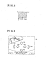
- a display area of the monitor display 17 illustrated in FIG. 5 displays a vehicle rear view (a live image) captured by the camera 11 and a graphic image of a reference marker 31 (illustrated in FIG. 6) representing the target parking position.
- the speaker 18 functions as a warning means and diffuses predetermined audio instructions corresponding to each stage of a parking procedure, which will be described later.
- the controller 20 is accommodated, for example inside of an instrument panel.
- the controller 20 operates for displaying the vehicle rear view captured by the camera 11 and the graphic image such as the reference marker 31 in the monitor display 17 and for diffusing the predetermined audio instructions based upon the signals from the camera 11, and other units 13 through 16.
- the controller 20 further detects a relative relationship between the target parking position; which is set based upon the signal from the target parking position input switch 14, and an actual position of the vehicle 1 and judges whether or not the vehicle 1 can be parked at the target parking position based upon the detection. That is, the controller 20 functions as an inputting means, a displaying means, a detecting means, and a judging means.
- the controller 20 is provided with a central processing unit (i.e. CPU) 21, a graphic image generating circuit 22 for generating the graphic image that appears on the monitor display 17, a superimposing circuit 23, a synchronization separating circuit 24, and an audio instruction generating circuit 25.
- the CPU 21 functions as the inputting means, the judging means, and the detecting means and calculates in various manners therein. The CPU 21 hence judges whether or not the vehicle 1 can be parked at the target parking position.
- the graphic image generating circuit 22 generates the graphic image that appears on the monitor display 17.
- the superimposing circuit 23 superimposes the graphic signal and the vehicle rear view captured by the camera 11.
- the synchronization separating circuit 24 extracts a synchronization signal from the image of the camera 11 and supplies the signal to the graphic image generating circuit 22.
- the audio instruction generating circuit 25 generates an audio instruction that is diffused by the speaker 18 to the driver.
- the input screen 30 shows the target parking position input switch 14 and the reference marker 31 representing the target parking position.
- the target parking position input switch 14 include arrowheads 14a, 14b, 14c, and 14d, which respectively indicates upward, rightward, downward, and leftward directions, and arrowheads 14e and 14f, which respectively indicates turning in both directions.
- the reference marker 31 representing the target parking position possesses an approximately square-shaped structure and is movably controlled in the input screen 30 in accordance with the arrowheads 14a through 14f.
- the CPU 21 is transmitted with a signal from each arrowhead 14a through 14f touched by the driver, wherein the reference marker 31 is moved to an intended position and the direction thereof is changed based upon each signal inputted into the CPU 21.
- the CPU 21 After moving the reference marker 31 to the intended position, the CPU 21 once memorizes the target parking position and the vehicle direction at the target parking position in response to a signal from a determining portion 32 touched by the driver.
- the CPU 21 further judges whether or not the vehicle 1 can be parked at the target parking position based upon later-described three geometrical relationships between the actual vehicle condition and the target parking position. The judgment is performed corresponding to whether or not the vehicle 1 can be parked at the target parking position in combination with a single turning movement and a straight movement thereto. An expected path can be defined based upon the combination of the single turning movement and the straight movement. The vehicle 1 can be judged by the CPU 21 to be able to be parked at the target parking position when the three geometrical relationships are satisfied. Further, the operation of the parking assist system 2 is terminated by touching an assist canceling portion 33 shown on the input screen 30 as needed.
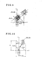
- the CPU 21 determines a coordinate system (X, Z) of the vehicle 1, which consists of an X axis and a Z axis, based upon an actual posture of the vehicle 1 when judging whether or not the vehicle 1 can be parked at the target parking position.
- the X axis extends in a right and left-hand side direction of the vehicle 1 and the Z axis extends in a forward and rearward direction thereof.
- the actual position of the vehicle 1 is set at an original point (0,0).
- the CPU 21 calculates and memorizes an coordinate (X0, Z0) of the target parking position based upon a relationship of the original point (0,0) relative thereto.
- the CPU 21 sets and memorizes a vehicle inclining degree at the target parking position as a parking angle ⁇ which is defined relative to a moving direction of the vehicle 1 at the original point (0, 0).
- the value of K calculated in accordance with the aforementioned equation should be substantially equal to or greater than a value represented by the x-coordinate X0 so as to park the vehicle 1 at the target parking position in combination with the single turning movement and the straight movement. That is, a straight line extending from the coordinate (X0, Z0) with the parking angle ⁇ relative to the Z axis is required to intersect with the X axis within a negative area of the X axis.
- the following second geometrical relationship is required to be satisfied so as to judge whether or not the vehicle 1 can be parked at the target parking position.
- a turning radius forming an expected arched path of the vehicle 1 to the target parking position is required to be greater than a minimum turning radius (Rmin) of the vehicle 1 determined based upon vehicle turning characteristics so as to smoothly park the vehicle 1 at the target parking position.
- the numeric value designated by "L1” represents a distance from the vehicle 1 to the target parking position when the vehicle 1 is moving straight after the turning operation.
- the numeric value designated by “D” represents a distance between a guiding center of the minimum turning operation of the velhicle 1 at the original point (0, 0) and the coordinate (X1, Z1).
- the numeric value designated by “D” is required to be substantially equal to or greater than the minimum turning radius (Rmin).
- the following third geometrical relationship is required to be satisfied so as to judge whether or not the vehicle 1 can be parked at the target parking position.
- the vehicle 1 can not be turned at a radius being less than the minimum turning radius Rmin so as to park the vehicl1 at the target vehicle position at a target angle. Therefore, when the parking angle ⁇ at the coordinate (X1, Z1) is greater than a vehicle angle (i.e. an angle on a path) ⁇ generated in response to the turning movement of the vehicle 1 at the minimum turning radius Rmin, the vehicle can not be turned.
- a vehicle angle i.e. an angle on a path
- the vehicle angle ⁇ is required to be substantially equal to or greater than the parking angle ⁇ .
- the CPU 21 judges that the vehicle 1 can be easily and properly parked at the target parking position.
- the monitor display 17 hence indicates that the vehicle 1 can be parked at the target parking position and the speaker 18 diffuses the predetermined audio instruction for announcing the driver that the vehicle 1 can be parked at the target parking position.
- the CPU 21 judges that the vehicle 1 can not be easily and properly parked at the target parking position.
- the monitor display 17 hence indicates that the vehicle 1 can not be parked at the target parking position and the speaker 18 diffuses the predetermined audio instruction for announcing the driver that the vehicle 1 can not be parked at the target parking position.
- the CPU 21 further judges whether or not the vehicle 1 can be parked at the target parking position based upon a geometrical relationship between the actual vehicle condition and the target parking position.
- the CPU 21 judges whether or not the vehicle 1 can be parked at the target parking position on the assumption that the actual vehicle is substantially parallel to a vehicle direction parked at the target parking position.
- the CPU 21 judges that the vehicle 1 can be parallel-parked at the target parking space in accordance with a following geometrical relationship when the vehicle 1 can be parallel-parked in combination with a single turning operation to one side of the vehicle 1, a single turning operation to the other side of the vehicle 1, and a straight movement.
- the CPU 21 determines the actual position of the vehicle 1 at the original point (0,0).
- the CPU 21 further calculates and memorizes the coordinate (X0, Z0) of the target parking position.
- the vehicle 1 can not be turned at a radius being less than the minimum turning radius Rmin. Therefore, the following conditional expression is required to be satisfied so as to park the vehicle 1 at the target parking position; (2Rmin - X0) 2 + Z0 2 ⁇ (2Rmin) 2 .
- the CPU 21 judges that the vehicle 1 can be easily and properly parked at the target parking position.
- the monitor display 17 hence indicates that the vehicle 1 can be parked at the target parking position and the speaker 18 diffuses the predetermined audio instruction for announcing the driver that the vehicle 1 can be parked at the target parking position.
- the CPU 21 judges that the vehicle 1 can not be easily and properly parked at the target parking position.
- the monitor display 17 hence indicates that the vehicle 1 can not be parked at the target parking position and the speaker 18 diffuses the predetermined audio instruction for announcing the driver that the vehicle 1 can not be parked at the target parking position.
- the present invention is not limited to the above-described embodiment and can be applied to modifications of the above-described embodiment.
- the parking assist system 2 is activated in response to operating the ordinary-parking mode switch 15a.
- the parking assist system 2 can be activated by recognizing a voice of the driver.
- the image screen appearing on the monitor display 7 and the audio instructions from the speaker 18 are respectively switched as needed.
- the image screen switching mechanism and the audio instruction switching mechanism sometimes are not required in response to the driver's driving ability. Therefore, the image screen switching mechanism and the audio instruction switching mechanism can be set non-operative for each driver.
- the camera 11 is provided at the rear portion of the vehicle 1 so as to assist the parking operation of the vehicle 1 in the rearward direction.
- the camera 11 can be provided at a front portion of the vehicle 1 so as to assist the parking operation of the vehicle 1 in a forward direction.
- the parking assist operation is completed by the parking assist system 2 installed on the vehicle 1.
- the vehicle 1 can be parked with an assist in response to an external signal from an external device.
- a parking assist system includes an image obtaining means for obtaining an image of a view from a vehicle, a displaying means for displaying the image obtained by the image obtaining means in a monitor display provided in the vehicle, an inputting means for inputting a target parking position, at which the vehicle is parked, on the monitor display, a detecting means for detecting a relative relationship between the vehicle and the target parking position, and a judging means for judging whether or not the vehicle can be parked at the target parking position based upon the relative relationship detected by the detecting means.
Landscapes
- Engineering & Computer Science (AREA)
- Mechanical Engineering (AREA)
- Transportation (AREA)
- Multimedia (AREA)
- Chemical & Material Sciences (AREA)
- Combustion & Propulsion (AREA)
- Radar, Positioning & Navigation (AREA)
- Remote Sensing (AREA)
- Human Computer Interaction (AREA)
- Traffic Control Systems (AREA)
- Closed-Circuit Television Systems (AREA)
Applications Claiming Priority (2)
| Application Number | Priority Date | Filing Date | Title |
|---|---|---|---|
| JP2002105769A JP4342146B2 (ja) | 2002-04-08 | 2002-04-08 | 駐車補助装置 |
| JP2002105769 | 2002-04-08 |
Publications (3)
| Publication Number | Publication Date |
|---|---|
| EP1352782A2 true EP1352782A2 (de) | 2003-10-15 |
| EP1352782A3 EP1352782A3 (de) | 2004-12-29 |
| EP1352782B1 EP1352782B1 (de) | 2007-07-04 |
Family
ID=28449911
Family Applications (1)
| Application Number | Title | Priority Date | Filing Date |
|---|---|---|---|
| EP03007895A Expired - Lifetime EP1352782B1 (de) | 2002-04-08 | 2003-04-07 | Vorrichtung zur Einparkhilfe |
Country Status (4)
| Country | Link |
|---|---|
| US (1) | US6950035B2 (de) |
| EP (1) | EP1352782B1 (de) |
| JP (1) | JP4342146B2 (de) |
| DE (1) | DE60314676T2 (de) |
Cited By (3)
| Publication number | Priority date | Publication date | Assignee | Title |
|---|---|---|---|---|
| WO2005044619A1 (de) * | 2003-11-06 | 2005-05-19 | Robert Bosch Gmbh | Verfahren zur ermittlung einer parklücke |
| WO2011029693A1 (de) | 2009-09-14 | 2011-03-17 | Robert Bosch Gmbh | Verfahren zum einparken eines fahrzeugs |
| EP3366525A4 (de) * | 2015-10-21 | 2018-12-05 | Hitachi Automotive Systems, Ltd. | Parkwegberechnungsvorrichtung, parkunterstützungsvorrichtung und parkwegberechnungsverfahren |
Families Citing this family (108)
| Publication number | Priority date | Publication date | Assignee | Title |
|---|---|---|---|---|
| US5877897A (en) | 1993-02-26 | 1999-03-02 | Donnelly Corporation | Automatic rearview mirror, vehicle lighting control and vehicle interior monitoring system using a photosensor array |
| US5910854A (en) | 1993-02-26 | 1999-06-08 | Donnelly Corporation | Electrochromic polymeric solid films, manufacturing electrochromic devices using such solid films, and processes for making such solid films and devices |
| US6822563B2 (en) | 1997-09-22 | 2004-11-23 | Donnelly Corporation | Vehicle imaging system with accessory control |
| US5668663A (en) | 1994-05-05 | 1997-09-16 | Donnelly Corporation | Electrochromic mirrors and devices |
| US6891563B2 (en) | 1996-05-22 | 2005-05-10 | Donnelly Corporation | Vehicular vision system |
| US7655894B2 (en) | 1996-03-25 | 2010-02-02 | Donnelly Corporation | Vehicular image sensing system |
| US6326613B1 (en) | 1998-01-07 | 2001-12-04 | Donnelly Corporation | Vehicle interior mirror assembly adapted for containing a rain sensor |
| US6172613B1 (en) | 1998-02-18 | 2001-01-09 | Donnelly Corporation | Rearview mirror assembly incorporating vehicle information display |
| US6124886A (en) | 1997-08-25 | 2000-09-26 | Donnelly Corporation | Modular rearview mirror assembly |
| US8294975B2 (en) | 1997-08-25 | 2012-10-23 | Donnelly Corporation | Automotive rearview mirror assembly |
| US6445287B1 (en) | 2000-02-28 | 2002-09-03 | Donnelly Corporation | Tire inflation assistance monitoring system |
| US8288711B2 (en) | 1998-01-07 | 2012-10-16 | Donnelly Corporation | Interior rearview mirror system with forwardly-viewing camera and a control |
| US6329925B1 (en) | 1999-11-24 | 2001-12-11 | Donnelly Corporation | Rearview mirror assembly with added feature modular display |
| US6477464B2 (en) | 2000-03-09 | 2002-11-05 | Donnelly Corporation | Complete mirror-based global-positioning system (GPS) navigation solution |
| US6693517B2 (en) | 2000-04-21 | 2004-02-17 | Donnelly Corporation | Vehicle mirror assembly communicating wirelessly with vehicle accessories and occupants |
| WO2001064481A2 (en) | 2000-03-02 | 2001-09-07 | Donnelly Corporation | Video mirror systems incorporating an accessory module |
| US7167796B2 (en) | 2000-03-09 | 2007-01-23 | Donnelly Corporation | Vehicle navigation system for use with a telematics system |
| US7195381B2 (en) | 2001-01-23 | 2007-03-27 | Donnelly Corporation | Vehicle interior LED lighting system |
| US7370983B2 (en) | 2000-03-02 | 2008-05-13 | Donnelly Corporation | Interior mirror assembly with display |
| US7255451B2 (en) | 2002-09-20 | 2007-08-14 | Donnelly Corporation | Electro-optic mirror cell |
| US7581859B2 (en) | 2005-09-14 | 2009-09-01 | Donnelly Corp. | Display device for exterior rearview mirror |
| AU2003225228A1 (en) | 2002-05-03 | 2003-11-17 | Donnelly Corporation | Object detection system for vehicle |
| US6918674B2 (en) | 2002-05-03 | 2005-07-19 | Donnelly Corporation | Vehicle rearview mirror system |
| WO2003105099A1 (en) | 2002-06-06 | 2003-12-18 | Donnelly Corporation | Interior rearview mirror system with compass |
| US7329013B2 (en) | 2002-06-06 | 2008-02-12 | Donnelly Corporation | Interior rearview mirror system with compass |
| US7274501B2 (en) | 2002-09-20 | 2007-09-25 | Donnelly Corporation | Mirror reflective element assembly |
| US7310177B2 (en) | 2002-09-20 | 2007-12-18 | Donnelly Corporation | Electro-optic reflective element assembly |
| DE10257722A1 (de) * | 2002-12-11 | 2004-07-01 | Robert Bosch Gmbh | Einparkhilfe |
| JP4427953B2 (ja) * | 2003-01-29 | 2010-03-10 | 株式会社豊田自動織機 | 駐車支援装置 |
| JP4235026B2 (ja) * | 2003-04-28 | 2009-03-04 | トヨタ自動車株式会社 | 駐車支援装置 |
| US7289037B2 (en) | 2003-05-19 | 2007-10-30 | Donnelly Corporation | Mirror assembly for vehicle |
| JP3866223B2 (ja) * | 2003-05-29 | 2007-01-10 | トヨタ自動車株式会社 | 車両用走行支援装置 |
| JP4316960B2 (ja) | 2003-08-22 | 2009-08-19 | 株式会社半導体エネルギー研究所 | 装置 |
| US7446924B2 (en) | 2003-10-02 | 2008-11-04 | Donnelly Corporation | Mirror reflective element assembly including electronic component |
| US7308341B2 (en) | 2003-10-14 | 2007-12-11 | Donnelly Corporation | Vehicle communication system |
| US7526103B2 (en) | 2004-04-15 | 2009-04-28 | Donnelly Corporation | Imaging system for vehicle |
| JP2005313710A (ja) | 2004-04-27 | 2005-11-10 | Toyota Motor Corp | 駐車支援装置 |
| DE102004027250A1 (de) * | 2004-06-03 | 2005-12-29 | Magna Donnelly Gmbh & Co. Kg | Verfahren und Vorrichtung zum unterstützten Steuern eines Kraftfahrzeuges |
| US7881496B2 (en) | 2004-09-30 | 2011-02-01 | Donnelly Corporation | Vision system for vehicle |
| JP4604703B2 (ja) * | 2004-12-21 | 2011-01-05 | アイシン精機株式会社 | 駐車補助装置 |
| US8065058B2 (en) * | 2004-12-24 | 2011-11-22 | Continental Teves Ag & Co. Ohg | Method for guiding a vehicle into a parking space and parking assistance device |
| EP1883855B1 (de) | 2005-05-16 | 2011-07-20 | Donnelly Corporation | Fahrzeugspiegelanordnung mit zeichen am reflektierenden teil |
| US8035531B2 (en) * | 2005-10-31 | 2011-10-11 | Toyota Jidosha Kabushiki Kaisha | Parking support device |
| CN101535087B (zh) | 2005-11-01 | 2013-05-15 | 唐纳利公司 | 具有显示装置的内部后视镜 |
| JP4414959B2 (ja) * | 2005-11-16 | 2010-02-17 | アイシン精機株式会社 | 駐車支援装置 |
| US8194132B2 (en) | 2006-01-20 | 2012-06-05 | Old World Industries, Llc | System for monitoring an area adjacent a vehicle |
| JP5577038B2 (ja) | 2006-03-09 | 2014-08-20 | ジェンテックス コーポレイション | 高輝度ディスプレイを含む車両リアビューアセンブリ |
| WO2008024639A2 (en) | 2006-08-11 | 2008-02-28 | Donnelly Corporation | Automatic headlamp control system |
| JP5003946B2 (ja) * | 2007-05-30 | 2012-08-22 | アイシン精機株式会社 | 駐車支援装置 |
| JP4919064B2 (ja) * | 2007-07-23 | 2012-04-18 | 株式会社デンソー | 車両用表示装置 |
| US8154418B2 (en) | 2008-03-31 | 2012-04-10 | Magna Mirrors Of America, Inc. | Interior rearview mirror system |
| JP2009292339A (ja) * | 2008-06-05 | 2009-12-17 | Aisin Seiki Co Ltd | 駐車支援装置 |
| US9487144B2 (en) | 2008-10-16 | 2016-11-08 | Magna Mirrors Of America, Inc. | Interior mirror assembly with display |
| US20100152972A1 (en) * | 2008-12-15 | 2010-06-17 | Joe Charles Attard | Parallel park assist |
| JP4790037B2 (ja) * | 2009-03-23 | 2011-10-12 | トヨタ自動車株式会社 | 駐車支援装置 |
| KR101532855B1 (ko) * | 2011-01-31 | 2015-06-30 | 도요타 지도샤(주) | 차량 제어 장치 |
| DE102011003881A1 (de) * | 2011-02-09 | 2012-08-09 | Robert Bosch Gmbh | Verfahren zur Unterstützung eines Fahrers eines Kraftfahrzeugs |
| DE112012003685T5 (de) * | 2011-09-05 | 2014-07-10 | Mitsubishi Electric Corp. | Bildverarbeitungsvorrichtung und Bildverarbeitungsverfahren |
| EP2808455B1 (de) * | 2012-01-27 | 2018-05-30 | Doosan Infracore Co., Ltd. | Vorrichtung zur erhöhung der betriebsstabilität einer baumaschine |
| US10457209B2 (en) | 2012-02-22 | 2019-10-29 | Magna Electronics Inc. | Vehicle vision system with multi-paned view |
| US9319637B2 (en) | 2012-03-27 | 2016-04-19 | Magna Electronics Inc. | Vehicle vision system with lens pollution detection |
| US8879139B2 (en) | 2012-04-24 | 2014-11-04 | Gentex Corporation | Display mirror assembly |
| US9707896B2 (en) | 2012-10-15 | 2017-07-18 | Magna Electronics Inc. | Vehicle camera lens dirt protection via air flow |
| US9445057B2 (en) | 2013-02-20 | 2016-09-13 | Magna Electronics Inc. | Vehicle vision system with dirt detection |
| WO2014150188A1 (en) | 2013-03-15 | 2014-09-25 | Gentex Corporation | Display mirror assembly |
| US9674490B2 (en) * | 2013-04-18 | 2017-06-06 | Magna Electronics Inc. | Vision system for vehicle with adjustable cameras |
| KR101448786B1 (ko) * | 2013-05-22 | 2014-10-13 | 현대자동차 주식회사 | 주차 보조 시스템 및 주차 정렬 제어 방법 |
| JP2016534915A (ja) | 2013-09-24 | 2016-11-10 | ジェンテックス コーポレイション | 表示ミラーアセンブリ |
| CN103625365B (zh) * | 2013-10-25 | 2016-08-24 | 江西好帮手电子科技有限公司 | 一种停车辅助监控系统及其实现方法 |
| KR101498973B1 (ko) * | 2013-11-21 | 2015-03-05 | 현대모비스(주) | 차량용 주차 지원 시스템 및 방법 |
| US9207677B2 (en) * | 2014-01-02 | 2015-12-08 | Automotive Research & Testing Center | Vehicle positioning method and its system |
| US9511715B2 (en) | 2014-01-31 | 2016-12-06 | Gentex Corporation | Backlighting assembly for display for reducing cross-hatching |
| EP3119643B1 (de) | 2014-03-21 | 2018-05-23 | Gentex Corporation | Trimodale anzeigespiegelanordnung |
| EP3126195B1 (de) | 2014-04-01 | 2019-06-05 | Gentex Corporation | Automatische anzeigespiegelanordnung |
| WO2016044746A1 (en) | 2014-09-19 | 2016-03-24 | Gentex Corporation | Rearview assembly |
| US9694752B2 (en) | 2014-11-07 | 2017-07-04 | Gentex Corporation | Full display mirror actuator |
| KR101977685B1 (ko) | 2014-11-13 | 2019-05-13 | 젠텍스 코포레이션 | 디스플레이를 갖춘 후방 미러 시스템 |
| CN107107825B (zh) | 2014-12-03 | 2020-08-21 | 金泰克斯公司 | 用于车辆的显示镜组件 |
| USD746744S1 (en) | 2014-12-05 | 2016-01-05 | Gentex Corporation | Rearview device |
| US9744907B2 (en) | 2014-12-29 | 2017-08-29 | Gentex Corporation | Vehicle vision system having adjustable displayed field of view |
| US9720278B2 (en) | 2015-01-22 | 2017-08-01 | Gentex Corporation | Low cost optical film stack |
| JP2018513810A (ja) | 2015-04-20 | 2018-05-31 | ジェンテックス コーポレイション | 装飾を備えた後方視認アセンブリ |
| US10112540B2 (en) | 2015-05-18 | 2018-10-30 | Gentex Corporation | Full display rearview device |
| KR102135427B1 (ko) | 2015-06-22 | 2020-07-17 | 젠텍스 코포레이션 | 진폭-변조된 광의 깜박임을 보정하기 위해 스트리밍된 비디오 이미지를 처리하는 시스템 및 방법 |
| EP3368374B1 (de) | 2015-10-30 | 2023-12-27 | Gentex Corporation | Umschaltpaddel |
| USD798207S1 (en) | 2015-10-30 | 2017-09-26 | Gentex Corporation | Rearview mirror assembly |
| USD797627S1 (en) | 2015-10-30 | 2017-09-19 | Gentex Corporation | Rearview mirror device |
| US9994156B2 (en) | 2015-10-30 | 2018-06-12 | Gentex Corporation | Rearview device |
| USD800618S1 (en) | 2015-11-02 | 2017-10-24 | Gentex Corporation | Toggle paddle for a rear view device |
| US9787951B2 (en) * | 2015-12-18 | 2017-10-10 | Serge Kannon | Vehicle proximity warning system |
| USD845851S1 (en) | 2016-03-31 | 2019-04-16 | Gentex Corporation | Rearview device |
| USD817238S1 (en) | 2016-04-29 | 2018-05-08 | Gentex Corporation | Rearview device |
| US10025138B2 (en) | 2016-06-06 | 2018-07-17 | Gentex Corporation | Illuminating display with light gathering structure |
| JP6868805B2 (ja) * | 2016-06-07 | 2021-05-12 | パナソニックIpマネジメント株式会社 | 画像生成装置、画像生成方法、およびプログラム |
| JP6644425B2 (ja) * | 2016-07-07 | 2020-02-12 | アルパイン株式会社 | 移動経路生成装置および移動経路生成方法 |
| EP3269679B2 (de) | 2016-07-14 | 2024-12-04 | Toyota Material Handling Manufacturing Sweden AB | Flurförderer |
| EP3269680B1 (de) | 2016-07-14 | 2020-09-30 | Toyota Material Handling Manufacturing Sweden AB | Flurförderer |
| EP3269678B1 (de) | 2016-07-14 | 2019-03-06 | Toyota Material Handling Manufacturing Sweden AB | Flurförderer |
| USD809984S1 (en) | 2016-12-07 | 2018-02-13 | Gentex Corporation | Rearview assembly |
| USD854473S1 (en) | 2016-12-16 | 2019-07-23 | Gentex Corporation | Rearview assembly |
| WO2018125898A1 (en) | 2016-12-30 | 2018-07-05 | Gentex Corporation | Full display mirror with on-demand spotter view |
| DE102017202259A1 (de) * | 2017-02-13 | 2018-08-16 | Ford Global Technologies, Llc | Verfahren und Vorrichtung zur Unterstützung eines Parkvorganges eines Kraftfahrzeuges |
| EP3595931A1 (de) | 2017-03-17 | 2020-01-22 | Gentex Corporation | Rückfahrkamera mit zwei anzeigen |
| DE102017106844A1 (de) | 2017-03-30 | 2018-10-04 | Valeo Schalter Und Sensoren Gmbh | Evaluierung der Komplexität eines Parkvorgangs |
| US10614721B2 (en) | 2017-06-08 | 2020-04-07 | International Business Machines Corporation | Providing parking assistance based on multiple external parking data sources |
| CN118714309A (zh) * | 2019-09-19 | 2024-09-27 | 数码士有限公司 | 使用缩放处理的视频信号处理方法及装置 |
| JP7766227B2 (ja) | 2021-08-20 | 2025-11-10 | ジェンテックス コーポレイション | 照明アセンブリ及び照明アセンブリを有する照射システム |
| WO2023105198A1 (en) * | 2021-12-06 | 2023-06-15 | Mbda Uk Limited | Apparatus and method for imaging |
Citations (1)
| Publication number | Priority date | Publication date | Assignee | Title |
|---|---|---|---|---|
| JPH11334470A (ja) | 1998-05-22 | 1999-12-07 | Aisin Seiki Co Ltd | 駐車補助装置 |
Family Cites Families (24)
| Publication number | Priority date | Publication date | Assignee | Title |
|---|---|---|---|---|
| US4931930A (en) * | 1988-04-19 | 1990-06-05 | Industrial Technology Research Institute | Automatic parking device for automobile |
| JP3396893B2 (ja) * | 1992-05-25 | 2003-04-14 | 株式会社デンソー | 車両の車庫誘導装置 |
| JPH082357A (ja) * | 1994-06-20 | 1996-01-09 | Nissan Motor Co Ltd | 車両用駐車補助装置 |
| JP3362569B2 (ja) * | 1995-08-04 | 2003-01-07 | 三菱自動車工業株式会社 | 車両誘導装置 |
| JP3362584B2 (ja) * | 1995-12-22 | 2003-01-07 | 三菱自動車工業株式会社 | 駐車判定装置 |
| JPH10264840A (ja) * | 1997-03-25 | 1998-10-06 | Nissan Motor Co Ltd | 駐車誘導装置 |
| JPH10264841A (ja) * | 1997-03-25 | 1998-10-06 | Nissan Motor Co Ltd | 駐車誘導装置 |
| JP3044534B2 (ja) * | 1997-04-28 | 2000-05-22 | 本田技研工業株式会社 | 車両の自動操舵装置 |
| JPH11157404A (ja) * | 1997-11-26 | 1999-06-15 | Toyota Motor Corp | 駐車支援装置 |
| JP3951465B2 (ja) * | 1998-06-26 | 2007-08-01 | アイシン精機株式会社 | 駐車補助装置 |
| FR2785383B1 (fr) * | 1998-10-30 | 2000-12-15 | Renault | Procede et dispositif d'assistance au deplacement d'un vehicule en vue en particulier de la parquer |
| JP4096445B2 (ja) * | 1999-03-31 | 2008-06-04 | アイシン精機株式会社 | 駐車補助装置 |
| JP2000335342A (ja) * | 1999-05-26 | 2000-12-05 | Yazaki Corp | 駐車支援装置 |
| JP4426014B2 (ja) * | 1999-06-29 | 2010-03-03 | 富士通テン株式会社 | 車両の駐車支援装置 |
| JP4104796B2 (ja) * | 1999-10-04 | 2008-06-18 | 矢崎総業株式会社 | 駐車支援装置 |
| JP3427823B2 (ja) * | 2000-02-29 | 2003-07-22 | 株式会社豊田自動織機 | 縦列駐車時の車両後退支援装置 |
| JP3374833B2 (ja) * | 2000-05-12 | 2003-02-10 | 株式会社豊田自動織機 | 駐車時の車両後退支援装置 |
| WO2001085496A1 (en) * | 2000-05-12 | 2001-11-15 | Kabushiki Kaisha Toyota Jidoshokki | Vehicle backing support apparatus |
| JP3693912B2 (ja) * | 2000-05-30 | 2005-09-14 | アイシン精機株式会社 | 相対位置検出装置及びその相対位置検出装置を備えた駐車補助装置 |
| JP3466549B2 (ja) * | 2000-07-03 | 2003-11-10 | トヨタ自動車株式会社 | 縦列駐車支援装置 |
| JP3619753B2 (ja) * | 2000-07-03 | 2005-02-16 | トヨタ自動車株式会社 | 移動体の後方視界表示装置 |
| JP2002036991A (ja) * | 2000-07-27 | 2002-02-06 | Honda Motor Co Ltd | 駐車支援装置 |
| JP3700614B2 (ja) * | 2001-06-22 | 2005-09-28 | 株式会社豊田自動織機 | 駐車支援装置 |
| US6683539B2 (en) * | 2001-12-27 | 2004-01-27 | Koninklijke Philips Electronics N.V. | Computer vision based parking assistant |
-
2002
- 2002-04-08 JP JP2002105769A patent/JP4342146B2/ja not_active Expired - Fee Related
-
2003
- 2003-04-07 DE DE60314676T patent/DE60314676T2/de not_active Expired - Lifetime
- 2003-04-07 EP EP03007895A patent/EP1352782B1/de not_active Expired - Lifetime
- 2003-04-08 US US10/408,232 patent/US6950035B2/en not_active Expired - Lifetime
Patent Citations (1)
| Publication number | Priority date | Publication date | Assignee | Title |
|---|---|---|---|---|
| JPH11334470A (ja) | 1998-05-22 | 1999-12-07 | Aisin Seiki Co Ltd | 駐車補助装置 |
Cited By (6)
| Publication number | Priority date | Publication date | Assignee | Title |
|---|---|---|---|---|
| WO2005044619A1 (de) * | 2003-11-06 | 2005-05-19 | Robert Bosch Gmbh | Verfahren zur ermittlung einer parklücke |
| US8279087B2 (en) | 2003-11-06 | 2012-10-02 | Robert Bosch Gmbh | Method for determining a parking spot |
| WO2011029693A1 (de) | 2009-09-14 | 2011-03-17 | Robert Bosch Gmbh | Verfahren zum einparken eines fahrzeugs |
| DE102009029436A1 (de) | 2009-09-14 | 2011-03-24 | Robert Bosch Gmbh | Verfahren zum Einparken eines Fahrzeugs |
| EP3366525A4 (de) * | 2015-10-21 | 2018-12-05 | Hitachi Automotive Systems, Ltd. | Parkwegberechnungsvorrichtung, parkunterstützungsvorrichtung und parkwegberechnungsverfahren |
| US10449969B2 (en) | 2015-10-21 | 2019-10-22 | Hitachi Automotive Systems, Ltd. | Parking path calculation device, parking assist device and parking path calculation method |
Also Published As
| Publication number | Publication date |
|---|---|
| US20030222793A1 (en) | 2003-12-04 |
| DE60314676D1 (de) | 2007-08-16 |
| EP1352782B1 (de) | 2007-07-04 |
| EP1352782A3 (de) | 2004-12-29 |
| JP2003300443A (ja) | 2003-10-21 |
| JP4342146B2 (ja) | 2009-10-14 |
| DE60314676T2 (de) | 2008-04-10 |
| US6950035B2 (en) | 2005-09-27 |
Similar Documents
| Publication | Publication Date | Title |
|---|---|---|
| EP1352782B1 (de) | Vorrichtung zur Einparkhilfe | |
| EP1160146B2 (de) | Parkhilfe | |
| US6483442B2 (en) | Parking aid system | |
| JP5115782B2 (ja) | 駐車支援装置 | |
| EP3031687B1 (de) | Fahrspurfunktionen für fahrzeuge mit einem anhänger | |
| JP5155222B2 (ja) | 車両の出庫モード選択表示装置 | |
| EP2776295B1 (de) | Parkhilfesystem | |
| JP4946682B2 (ja) | 車両用走行支援装置 | |
| WO2009081519A1 (en) | Vehicle parking assist system and method | |
| EP1022903A2 (de) | Hilfsgerät für die Rückwärtsfahrt eines Fahrzeuges | |
| EP2402219A1 (de) | Parkhilfevorrichtung | |
| JP6014433B2 (ja) | 画像処理装置、画像処理方法、及び、画像処理システム | |
| JP5182137B2 (ja) | 車両周辺表示装置 | |
| US11577782B2 (en) | Method and apparatus for an automated trailer backup system in a motor vehicle | |
| JP2008162426A (ja) | 駐車支援装置 | |
| JP2006051850A (ja) | 運転支援装置及び運転支援方法 | |
| JP3726175B2 (ja) | 駐車補助装置 | |
| JP4936060B2 (ja) | 車両用走行支援装置 | |
| JP2007221200A (ja) | 車両周辺監視装置 | |
| JP2007022176A (ja) | 車両周辺視認装置 | |
| JP2004123057A (ja) | 駐車支援装置 | |
| JP2004051063A (ja) | 車両周辺視認装置 | |
| JP2011000933A (ja) | 周辺認知支援装置 | |
| JP2001334898A (ja) | 駐車補助装置 | |
| JP4821347B2 (ja) | 脇見運転防止装置 |
Legal Events
| Date | Code | Title | Description |
|---|---|---|---|
| PUAI | Public reference made under article 153(3) epc to a published international application that has entered the european phase |
Free format text: ORIGINAL CODE: 0009012 |
|
| AK | Designated contracting states |
Kind code of ref document: A2 Designated state(s): AT BE BG CH CY CZ DE DK EE ES FI FR GB GR HU IE IT LI LU MC NL PT RO SE SI SK TR |
|
| AX | Request for extension of the european patent |
Extension state: AL LT LV MK |
|
| RIN1 | Information on inventor provided before grant (corrected) |
Inventor name: TANAKA, YUU Inventor name: IWAZAKI, KATSUHIKO,C/O TOYOTA JIDOSHA KABUSHIKI K Inventor name: ENDO, TOMOHIKO,C/O TOYOTA JIDOSHA KABUSHIKI K. Inventor name: KATAOKA, HIROAKI,C/O TOYOTA JIDOSHA KABUSHIKI K. Inventor name: KAWAKAMI, SEIJI,C/O TOYOTA JIDOSHA KABUSHIKI K. Inventor name: MORITA, MITSUHIKO,C/O TOYOTA JIDOSHA KABUSHIKI K. Inventor name: SATONAKA, HISASHI,C/O TOYOTA JIDOSHA KABUSHIKI K. Inventor name: IWATA, YOSHIFUMI |
|
| PUAL | Search report despatched |
Free format text: ORIGINAL CODE: 0009013 |
|
| AK | Designated contracting states |
Kind code of ref document: A3 Designated state(s): AT BE BG CH CY CZ DE DK EE ES FI FR GB GR HU IE IT LI LU MC NL PT RO SE SI SK TR |
|
| AX | Request for extension of the european patent |
Extension state: AL LT LV MK |
|
| 17P | Request for examination filed |
Effective date: 20050530 |
|
| AKX | Designation fees paid |
Designated state(s): DE FR GB |
|
| GRAP | Despatch of communication of intention to grant a patent |
Free format text: ORIGINAL CODE: EPIDOSNIGR1 |
|
| GRAS | Grant fee paid |
Free format text: ORIGINAL CODE: EPIDOSNIGR3 |
|
| GRAA | (expected) grant |
Free format text: ORIGINAL CODE: 0009210 |
|
| AK | Designated contracting states |
Kind code of ref document: B1 Designated state(s): DE FR GB |
|
| REG | Reference to a national code |
Ref country code: GB Ref legal event code: FG4D |
|
| REF | Corresponds to: |
Ref document number: 60314676 Country of ref document: DE Date of ref document: 20070816 Kind code of ref document: P |
|
| ET | Fr: translation filed | ||
| PLBE | No opposition filed within time limit |
Free format text: ORIGINAL CODE: 0009261 |
|
| STAA | Information on the status of an ep patent application or granted ep patent |
Free format text: STATUS: NO OPPOSITION FILED WITHIN TIME LIMIT |
|
| 26N | No opposition filed |
Effective date: 20080407 |
|
| GBPC | Gb: european patent ceased through non-payment of renewal fee |
Effective date: 20080407 |
|
| PG25 | Lapsed in a contracting state [announced via postgrant information from national office to epo] |
Ref country code: GB Free format text: LAPSE BECAUSE OF NON-PAYMENT OF DUE FEES Effective date: 20080407 |
|
| PGFP | Annual fee paid to national office [announced via postgrant information from national office to epo] |
Ref country code: DE Payment date: 20110330 Year of fee payment: 9 Ref country code: FR Payment date: 20110426 Year of fee payment: 9 |
|
| REG | Reference to a national code |
Ref country code: FR Ref legal event code: ST Effective date: 20121228 |
|
| PG25 | Lapsed in a contracting state [announced via postgrant information from national office to epo] |
Ref country code: FR Free format text: LAPSE BECAUSE OF NON-PAYMENT OF DUE FEES Effective date: 20120430 |
|
| REG | Reference to a national code |
Ref country code: DE Ref legal event code: R119 Ref document number: 60314676 Country of ref document: DE Effective date: 20121101 |
|
| PG25 | Lapsed in a contracting state [announced via postgrant information from national office to epo] |
Ref country code: DE Free format text: LAPSE BECAUSE OF NON-PAYMENT OF DUE FEES Effective date: 20121101 |