EP1352995A1 - Head piece made of polymer material for a carding flat - Google Patents
Head piece made of polymer material for a carding flat Download PDFInfo
- Publication number
- EP1352995A1 EP1352995A1 EP03003518A EP03003518A EP1352995A1 EP 1352995 A1 EP1352995 A1 EP 1352995A1 EP 03003518 A EP03003518 A EP 03003518A EP 03003518 A EP03003518 A EP 03003518A EP 1352995 A1 EP1352995 A1 EP 1352995A1
- Authority
- EP
- European Patent Office
- Prior art keywords
- end head
- lid end
- flat
- head according
- polymer material
- Prior art date
- Legal status (The legal status is an assumption and is not a legal conclusion. Google has not performed a legal analysis and makes no representation as to the accuracy of the status listed.)
- Granted
Links
Images


Classifications
-
- D—TEXTILES; PAPER
- D01—NATURAL OR MAN-MADE THREADS OR FIBRES; SPINNING
- D01G—PRELIMINARY TREATMENT OF FIBRES, e.g. FOR SPINNING
- D01G15/00—Carding machines or accessories; Card clothing; Burr-crushing or removing arrangements associated with carding or other preliminary-treatment machines
- D01G15/02—Carding machines
- D01G15/12—Details
- D01G15/14—Constructional features of carding elements, e.g. for facilitating attachment of card clothing
- D01G15/24—Flats or like members
-
- D—TEXTILES; PAPER
- D01—NATURAL OR MAN-MADE THREADS OR FIBRES; SPINNING
- D01G—PRELIMINARY TREATMENT OF FIBRES, e.g. FOR SPINNING
- D01G15/00—Carding machines or accessories; Card clothing; Burr-crushing or removing arrangements associated with carding or other preliminary-treatment machines
- D01G15/02—Carding machines
- D01G15/12—Details
- D01G15/28—Supporting arrangements for carding elements; Arrangements for adjusting relative positions of carding elements
Definitions
- the present invention relates to a flat end head of a flat bar for a Revolving cover of a card or card.
- a large number of flat bars are used in generic cards or cards guided over the card drum on a sliding guide.
- This arrangement is called also revolving cover. They are by an endless element, for example a belt or a chain, connected and are moved by a drive element.
- Both the Flat bars as well as the drum have a set, for example fine needles or in the form of a saw tooth, which interact with each other for cleaning and the parallelization of the fibers are decisive.
- the Carding gap between the two sets is at most a few Tenth of a millimeter.
- the flat bars each have a flat end head at their ends.
- the Lid end head has an attachment area for attachment to the end of the Flat bars and at least one sliding surface.
- the lid end head also has another device to fix the endless element, for example one Recess.
- An example of such a combination of flat rod, endless element, and the lid end head can be found in the patent EP0 627 507 B1.
- the sliding surfaces of the lid end heads are also the surfaces, making the whole Flat rod rests on the slide guides. You still have the task of To interact with the sliding guide and for a low-friction and dimensionally accurate run of the flat bar. It is therefore important that the end cap and the Sliding guide are precisely matched to each other, so that the distance between Flat rod and drum (each of the clothing tips) in a predetermined Tolerance range can be kept.
- the Slideway and / or the sliding surface of the lid end head wear. in the essential is the wear of the sliding guide or the sliding surface of the Lid end heads a question of the material pairing used.
- the wear can also be reduced or minimized through the use of lubrication systems (e.g. Oil lubrication).
- the sliding guide on the card is traditionally made of cast iron.
- the newer state the technology discloses sliding guides with sliding strips made of polymer material, for example EP 620 296 or EP 361 219. The latter does not disclose which Material for the lid end head is needed.
- EP 620 296 discloses for Cast iron or sturdy metal end caps. In addition to these materials also solid steel (US 4,827,573) or an aluminum / aluminum alloy (US 4,300,266) for the manufacture of the lid end heads. In these However, patents do not provide any information about the material for the sliding guide made.
- sliding shoes can be found in US Pat. No. 4,300,266, the Material for the slide shoe phosphor / bronze or a polymer material, for Example MoS2 / nylon or a combination that contains PTFE.
- Patent DE 198 34 893 publishes a polymer material sliding shoe Polyamide.
- the current flat bars are made of steel or cast iron and partly equipped with sliding shoes. Although these Combination meets the requirements of the flat bars, this is to be made disadvantageous. Depending on the type, around 100 flat bars are used on one machine. Each additional component on a complete flat rod increases the Production expenses.
- the object of the invention is to optimize the end cap under Consideration of the material pairing and the problem described above.
- a solution according to the invention provides that the entire end of the lid is made from one To produce pieces from a polymer material.
- a lid end head consists of several areas: the first area is responsible for fastening with the flat bar, the second area consists of the actual one Head that rests on the sliding guide and additional corresponding sliding surfaces adduced. One of these areas could also have a device for the Have attachment of the endless element.
- Another solution according to the invention provides fiber reinforcement of the Polymer material before. This can increase the strength of the end cap.
- the approach between the attachment area and the actual head is during the operation of the revolving cover exposed to several forces.
- the flat bar will only carried by its lid end heads. In order to ensure an exact measurement these end caps must not bend. In addition, they are, through the side Movement of the flat bars through the drive element, also torsional forces exposed. A twisting of the material would also negatively affect the dimensioning influence.
- the entire lid end head is made of one material is manufactured that wears out.
- the selected fiber material can then be sent to the Surface of the sliding surface.
- Abrasive fibers could then be an undesirable one Cause the sliding guide to rub.
- Carbon fibers for example PAN fibers®
- aramid fibers polyamideimide fibers, for example Kevlar®
- a mixture of the two fibers could also be used. Especially since that Aramid fibers show a favorable wear behavior compared to the sliding partner and the carbon fibers achieve better strength. Combining results in an optimal solution.
- An additional solution according to the invention is a lid end head made of a Polymer material with solid lubricant additive. Trials have shown that not everyone Combination of a base polymer material and solid lubricant on cast iron shows optimal lubricity and lubrication properties. preferred Combinations are shown in Table 1, column 1 are again the preferred ones Groups of base polymer materials listed and the preferred in column 2 Solid lubricants that are used for the task of the end cap as the most appropriate show.
- Solid lubricants In order to obtain the desired sliding properties, 1-15% by weight of solid lubricants are required, preferably 5-12% by weight, very preferably 8-11% by weight. In the case of molybdenum disulfide (MoS2) and polysiloxane, a smaller amount of solid lubricants is sufficient, for these 2 solid lubricants 1-6% by weight, preferably 1-3% by weight, for example 2% by weight, are preferred.
- Preferred combinations of base polymer material and solid lubricant Based on polymer material lubricant a. PTFE (fiber or powder) I. Polyamide PA b. Polysiloxane (silicone) c. graphite d. polyethylene e. Molybdenum disulfide (MoS2) II.
- Polyoxymethylene POM a. Polysiloxane (silicone) b. PTFE (fiber or powder) III. terephthalate a. PTFE (powder or fiber) IV. Polyetheretherketone PEEK a. PTFE (powder or fiber) a. PTFE (powder or fiber) V. Polyimide PI b. graphite c. MoS2
- the lid end heads can be manufactured using an injection molding process.
- FIG 1 shows how the flat end head with the flat bar and the sliding guide on one Teasel works together.
- the flat rod is formed by a hollow profile, part of which is used as a holder for the lid end head.
- the end cap (1) is inserted into the flat rod (8) pushed in as far as it will go.
- the lid end head lies together Flat rod on the slide guide (6), (In Figure 2, this is from the side of the Drums shown. It can be clearly seen that the sliding guide is in the form of an arc follows the curvature of the drum.)
- the carding gap (12) is the distance between the Set (11) of the flat bar and the set (10) of the drum (9). This should be true to size.
- FIGS 3 and 4 show the lid end head in detail.
- a lid end head consists of several areas: the first area is responsible for the attachment with the Flat rod (1), the second area consists of the actual head (5) on the The sliding guide rests and additionally has corresponding sliding surfaces (2).
- One of Both areas could also have an additional option for the Attachment of the endless element, for example a recess (3) in the actual Head.
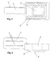
- Figures 5 and 6 show the same end caps as in Figures 3 and 4.
- the Sliding surface has at least one, advantageously a plurality of cleaning grooves (4)
- the purpose of these cleaning grooves is to remove impurities that are on the Have reached the sliding surface, to be removed or collected or removed.
- the Cleaning grooves are dimensioned so that they are sufficiently dirty can absorb until they are brushed out when cleaning the lid.
- the cleaning grooves also have a sufficient depth, which means that Grains of sand or other dirt no further contact with the Counter surface, i.e. the sliding guide. This is a removal of the Contamination without damaging or scratching the sliding guide or the Sliding surface of the lid end head possible. This creates an even surface ensures the sliding guide and thus a uniform abrasion of the sliding surface.
- one can hold the lid head firmly in the flat rod Profile (17) are attached to the fastening part of the lid end head, for example on at least one long side, raised longitudinal stripes (see FIG. 4 and 5, (17)).
- This profile has the task of inaccuracies in the hollow profile of the Lift the flat bar by counter pressure and increases the clamping of the Lid end head in the flat bar.
- At least one stop block is required. Disassembly takes place in that the cylinder (13) moves away from the flat rod in the longitudinal direction, the holder (14) holding the flat end head and pulling it out of the hollow profile. In order to ensure that the flat rod is not pulled along, a stop block (15) blocks the way. Assembly takes place in that the cylinder or piston (13), with the new end cap held by the holder, moves in the direction of the flat rod and thereby pushes the end cap into the hollow profile of the flat rod as far as it will go. In this case, the stop block (16) prevents the flat rod from being pushed away. Rounding of the edges and bevels of the lid end head according to the invention can simplify this process.
Landscapes
- Engineering & Computer Science (AREA)
- Textile Engineering (AREA)
- Preliminary Treatment Of Fibers (AREA)
- Reinforced Plastic Materials (AREA)
Abstract
Description
Die vorliegende Erfindung betrifft einen Deckelendkopf eines Deckelstabes für einen Wanderdeckel einer Karde oder Krempel.The present invention relates to a flat end head of a flat bar for a Revolving cover of a card or card.
In gattungsgemässen Karden oder Krempeln werden eine Vielzahl von Deckelstäben auf einer Gleitführung über die Kardentrommel geführt. Diese Anordnung nennt man auch Wanderdeckel. Sie sind durch ein Endloselement, zum Beispiel ein Riemen oder eine Kette, verbunden und werden durch ein Antriebselement fortbewegt. Sowohl die Deckelstäbe als auch der Tambour haben eine Garnitur, zum Beispiel feine Nadeln oder in Form eines Sägezahns, die miteinander in Wechselwirkung für die Reinigung und die Parallelisierung der Fasern massgebend sind. Um ein Kardierergebnis zu erzielen, ist es besonders wichtig, dass die Abstände der Deckelstäbe zu der Kardentrommel, bzw. der Abstand der Garniturspitzen, exakt eingehalten werden. Der Kardierspalt zwischen den beiden Garnituren beträgt höchstens ein paar Zehntelsmillimeter.A large number of flat bars are used in generic cards or cards guided over the card drum on a sliding guide. This arrangement is called also revolving cover. They are by an endless element, for example a belt or a chain, connected and are moved by a drive element. Both the Flat bars as well as the drum have a set, for example fine needles or in the form of a saw tooth, which interact with each other for cleaning and the parallelization of the fibers are decisive. To get a carding result achieve, it is particularly important that the distances between the flat bars to the Card drum, or the distance between the clothing tips, are observed exactly. The Carding gap between the two sets is at most a few Tenth of a millimeter.
Die Deckelstäbe weisen an ihren Enden jeweils je einen Deckelendkopf auf. Der Deckelendkopf hat ein Befestigungsbereich für die Befestigung mit dem Ende des Deckelstabs und mindestens eine Gleitfläche. In der Regel hat der Deckelendkopf auch noch eine Vorrichtung, um das Endloselement zu befestigen, zum Beispiel eine Aussparung. Ein Beispiel für solch eine Kombination aus Deckelstab, Endloselement, und Deckelendkopf findet man in der Patentschrift EP0 627 507 B1.The flat bars each have a flat end head at their ends. The Lid end head has an attachment area for attachment to the end of the Flat bars and at least one sliding surface. Usually the lid end head also has another device to fix the endless element, for example one Recess. An example of such a combination of flat rod, endless element, and the lid end head can be found in the patent EP0 627 507 B1.
Die Gleitflächen der Deckelendköpfe sind gleichzeitig die Flächen, womit der gesamte Deckelstab auf den Gleitführungen aufliegt. Sie haben weiter die Aufgabe, mit der Gleitführung zusammenzuwirken und für einen reibungsarmen und massgenauen Lauf des Deckelstabes zu sorgen. Es ist deshalb wichtig, dass der Deckelendkopf und die Gleitführung genau auf einander abgestimmt sind, so dass der Abstand zwischen Deckelstab und Trommel (Jeweils der Garniturspitzen) in einem vorgegebenen Toleranzbereich gehalten werden kann. The sliding surfaces of the lid end heads are also the surfaces, making the whole Flat rod rests on the slide guides. You still have the task of To interact with the sliding guide and for a low-friction and dimensionally accurate run of the flat bar. It is therefore important that the end cap and the Sliding guide are precisely matched to each other, so that the distance between Flat rod and drum (each of the clothing tips) in a predetermined Tolerance range can be kept.
Durch die gleitende Bewegung des Deckelendkopfes auf der Gleitführung unterliegt die Gleitführung und/oder die Gleitfläche des Deckelendkopfes einem Verschleiss. Im wesentlichen ist der Verschleiss der Gleitführung oder die Gleitfläche der Deckelendköpfe eine Frage der verwendeten Materialpaarung. Der Verschleiss kann auch durch dern Einsatz von Schmiereinrichtungen reduziert bzw. minimiert werden ( z.B. Ölschmierung).Due to the sliding movement of the lid end head on the sliding guide, the Slideway and / or the sliding surface of the lid end head wear. in the essential is the wear of the sliding guide or the sliding surface of the Lid end heads a question of the material pairing used. The wear can can also be reduced or minimized through the use of lubrication systems ( e.g. Oil lubrication).
Die Gleitführung an der Karde ist traditionellerweise aus Gusseisen. Der neuere Stand der Technik offenbart Gleitführungen mit Gleitstreifen aus Polymerwerkstoff, beispielsweise EP 620 296 oder EP 361 219. Letzteres offenbart nicht, welches Material für den Deckelendkopf gebraucht wird. EP 620 296 offenbart für die Deckelendköpfe Gusseisen oder stabiles Metall. Neben diesen Werkstoffen werden auch noch massiver Stahl (US 4,827,573) oder eine Aluminium/ Aluminiumlegierung (US 4,300,266) für die Herstellung der Deckelendköpfe genannt. In diesen Patentschriften wird allerdings keine Angaben über das Material für die Gleitführung gemacht.The sliding guide on the card is traditionally made of cast iron. The newer state the technology discloses sliding guides with sliding strips made of polymer material, for example EP 620 296 or EP 361 219. The latter does not disclose which Material for the lid end head is needed. EP 620 296 discloses for Cast iron or sturdy metal end caps. In addition to these materials also solid steel (US 4,827,573) or an aluminum / aluminum alloy (US 4,300,266) for the manufacture of the lid end heads. In these However, patents do not provide any information about the material for the sliding guide made.
Um die Gleitfähigkeit dieser Deckelendköpfe zu erhöhen, sieht der Stand der Technik auch Gleitschuhe vor, die am Deckelendkopf befestigt werden. Patentschrift US 4,300,266 zum Beispiel zeigt einen Deckelschuh, der bei Bedarf austauschbar ist. Allerdings wird dieser Deckelschuh in axialer Richtung auf den Deckelkopf aufgeschoben und mittels Klipse befestigt. Ein Nachteil dieser Lösung ist der erhebliche Aufwand beim Umtausch der Deckelschuhe. Das Spiel in der Richtung senkrecht zur Längsachse des Deckelstabes, das gebraucht wird um den Deckelschuh auf den Deckelstab zu schieben, ist nachteilig für die exakte Zuordnung des Deckelstabes zur Trommel.In order to increase the sliding ability of these lid end heads, the state of the art sees also slide shoes that are attached to the lid end head. US patent 4,300,266, for example, shows a lid shoe that can be replaced if necessary. However, this lid shoe is in the axial direction on the lid head pushed on and fastened with clips. A disadvantage of this solution is the considerable one Effort when exchanging the lid shoes. The game in the direction perpendicular to Longitudinal axis of the flat bar, which is needed around the flat shoe on the Pushing the flat bar is disadvantageous for the exact assignment of the flat bar to Drum.
Andere Beispiele von Gleitschuhen findet man in der Patentschrift US 4,300,266, die als Werkstoff für den Gleitschuh Phosphor /Bronze oder einen Polymerwerkstoff, zum Beispiel MoS2/Nylon oder eine Kombination die PTFE enthält, vorschlägt. Patentschrift DE 198 34 893 veröffentlicht einen Polymerwerkstoff Gleitschuh zum Beispiel aus Polyamid. Other examples of sliding shoes can be found in US Pat. No. 4,300,266, the Material for the slide shoe phosphor / bronze or a polymer material, for Example MoS2 / nylon or a combination that contains PTFE. Patent DE 198 34 893, for example, publishes a polymer material sliding shoe Polyamide.
In der Praxis werden Gleitschuhe auch geklebt. Nachteilig bei einem Austausch ist nicht nur der Mehraufwand, um den alten Gleitschuh und Klebstoffrückstände zu entfernen. Sondern beim Kleben von dem neuen Schuh können auch Klebstoffverschmierungen entstehen, die den Deckelstab in seiner Funktion erheblich beeinträchtigen können. Nur durch sehr präzises Arbeiten können diese Verschmutzungen verhindert werden, dieses bedingt aber einen erheblichen Mehraufwand.In practice, sliding shoes are also glued. An exchange is not a disadvantage only the extra effort to remove the old shoe and adhesive residues. But when gluing the new shoe you can also use glue smears arise that can significantly impair the function of the flat rod. Just this contamination can be prevented by working very precisely, however, this requires a considerable additional effort.
Zusammenfassend werden bei den jetzigen Deckelstäben Deckelendköpfe aus Stahl oder Gusseisen verwendet und zum Teil mit Gleitschuhen versehen. Obwohl diese Kombination den Anforderung der Deckelstäbe genügt, ist diese zum Herstellen nachteilig. An einer Maschine werden je nach Typ rund 100 Deckelstäbe eingesetzt. Jede zusätzliche Komponente an einem kompletten Deckelstab erhöht den Produktionsaufwand.In summary, the current flat bars are made of steel or cast iron and partly equipped with sliding shoes. Although these Combination meets the requirements of the flat bars, this is to be made disadvantageous. Depending on the type, around 100 flat bars are used on one machine. Each additional component on a complete flat rod increases the Production expenses.
Die Aufgabe der Erfindung besteht darin, den Deckelendkopf zu optimieren unter Berücksichtigung der Materialpaarung und der oben beschriebenen Problematik.The object of the invention is to optimize the end cap under Consideration of the material pairing and the problem described above.
Eine erfindungsgemässe Lösung sieht vor, den gesamten Deckelendkopf aus einem Stück aus einem Polymerwerkstoff herzustellen.A solution according to the invention provides that the entire end of the lid is made from one To produce pieces from a polymer material.
Interne Untersuchungen haben gezeigt, dass bei der Materialpaarung Gusseisen/Polymerwerkstoff
ähnliche verschleissmechanismen spielen wie bei einer
Materialpaarung Stahl/Polymerwerkstoff.
Für die Erfindungsgemässe Lösung wird vor allem eine Gleitführung aus Gusseisen
oder Stahl bevorzugt. Gleitführungen ganz oder Teilweise aus einem Polymerwerkstoff
könnten aber auch als Partner dienen für einen Deckelendkopf aus einem
Polymerwerkstoff wie diese Erfindung sie vorschlägt.Internal investigations have shown that the material pairing cast iron / polymer material plays similar wear mechanisms as with a material pairing steel / polymer material.
A sliding guide made of cast iron or steel is preferred for the solution according to the invention. Slideways made entirely or partially of a polymer material could also serve as partners for a cover end head made of a polymer material as proposed by this invention.
Ein Deckelendkopf besteht aus mehreren Bereichen: der erste Bereich ist zuständig für die Befestigung mit dem Deckelstab, der zweite Bereich besteht aus dem eigentlichen Kopf der auf der Gleitführung aufliegt und zusätzlich entsprechende Gleitflächen vorweist. Einer dieser Bereiche könnte auch noch zusätzlich eine Vorrichtung für die Befestigung des Endloselements aufweisen.A lid end head consists of several areas: the first area is responsible for fastening with the flat bar, the second area consists of the actual one Head that rests on the sliding guide and additional corresponding sliding surfaces adduced. One of these areas could also have a device for the Have attachment of the endless element.
Als Basis für den Deckelendkopf verwendet man als Polymerwerkstoff vorzugsweise:
- einen Werkstoff aus der Gruppe der Polyamide, beispielsweise Polyamid 66;
- ein Werkstoff aus der Gruppe der Polyoxymethylene (POM). Die Homo-Polymere (POM-H) und Co-Polymere (POM-C) können beide erfindungsgemäss eingesetzt werden. Beispiele sind Delrin® oder Hostaform®.
- einen Werkstoff aus der Gruppe der Terephthalate, vorzugsweise Polyethylenterephthalat (PETP) oder Polybutylenterephthalat (PBTP).
- einen Werkstoff aus der Gruppe der Polyetheretherketon (PEEK);
- oder einen Werkstoff aus der Gruppe der Polyimide (PI), beispielsweise Polyamidimide (PAI).
- a material from the group of polyamides, for example polyamide 66;
- a material from the group of polyoxymethylene (POM). The homopolymers (POM-H) and copolymers (POM-C) can both be used according to the invention. Examples are Delrin® or Hostaform®.
- a material from the group of terephthalates, preferably polyethylene terephthalate (PETP) or polybutylene terephthalate (PBTP).
- a material from the group of polyether ether ketone (PEEK);
- or a material from the group of polyimides (PI), for example polyamideimides (PAI).
Eine weitere erfindungsgemässe Lösung sieht eine Faserverstärkung des Polymerwerkstoffs vor. Damit kann die Festigkeit des Deckelendkopfes erhöht werden. Der Ansatz zwischen dem Befestigungsbereich und dem eigentlichen Kopf ist während des Betriebs der Wanderdeckel mehreren Kräften ausgesetzt. Der Deckelstab wird nur von seinen Deckelendköpfen getragen. Um eine genaue Massführung zu gewährleisten dürfen diese Deckelendköpfe nicht durchbiegen. Zusätzlich sind sie, durch die seitliche Bewegung der Deckelstäbe durch das Antriebselement, auch noch Torsionskräften ausgesetzt. Eine Verdrehung des Werkstoffs würde die Massführung ebenfalls negativ beeinflussen.Another solution according to the invention provides fiber reinforcement of the Polymer material before. This can increase the strength of the end cap. The approach between the attachment area and the actual head is during the operation of the revolving cover exposed to several forces. The flat bar will only carried by its lid end heads. In order to ensure an exact measurement these end caps must not bend. In addition, they are, through the side Movement of the flat bars through the drive element, also torsional forces exposed. A twisting of the material would also negatively affect the dimensioning influence.
Ein zusätzlicher Aspekt ist, dass der gesamte Deckelendkopf aus einem Material hergestellt wird, der verschleisst. Das gewählte Fasermaterial kann dadurch an die Oberfläche der Gleitfläche gelangen. Abrasive Fasern könnten dann ein unerwünschtes Scheuern der Gleitführung verursachen. Erfindungsgemäss werden vorzugsweise Kohlefasern (zum Beispiel PAN-Fasern®) oder Aramidfasern (Polyamidimid Fasern, zum Beispiel Kevlar®) verwendet. An additional aspect is that the entire lid end head is made of one material is manufactured that wears out. The selected fiber material can then be sent to the Surface of the sliding surface. Abrasive fibers could then be an undesirable one Cause the sliding guide to rub. According to the invention are preferred Carbon fibers (for example PAN fibers®) or aramid fibers (polyamideimide fibers, for example Kevlar®) is used.
Eine Mischung beider Fasern könnte auch verwendet werden. Vor allem da die Aramidfasern ein günstiger Verschleissverhalten gegenüber der Gleitpartner aufweisen und die Kohlefasern eine bessere Festigkeit erzielen. Durch kombinieren ergibt sich eine optimale Lösung.A mixture of the two fibers could also be used. Especially since that Aramid fibers show a favorable wear behavior compared to the sliding partner and the carbon fibers achieve better strength. Combining results in an optimal solution.
Für die erforderliche Festigkeit ist ein gesamter Faseranteil von 5 - 60 Gewichts-%,
vorzugsweise 30 - 50 Gewichts-% gefragt. Wenn nicht anders angegeben, Gewichts-%
ist in der gesamten Offenbarung immer berechnet auf das Endgewicht.
Bei einer Mischung von Aramidfasern und Kohlefasern, ist ein Aramidfaseranteil von
minimal 10 Gewichts-% bevorzugt.A total fiber content of 5-60% by weight, preferably 30-50% by weight, is required for the required strength. Unless otherwise stated,% by weight is always calculated on the final weight throughout the disclosure.
With a mixture of aramid fibers and carbon fibers, an aramid fiber content of at least 10% by weight is preferred.
Eine zusätzliche erfindungsgemässe Lösung ist ein Deckelendkopf aus einem
Polymerwerkstoff mit Festschmierstoffzusatz. Versuche haben gezeigt, dass nicht jede
Kombination aus einem Basispolymerwerkstoff und Festschmierstoff auf Gusseisen
eine optimale Gleitfähigkeit und Schmiereigenschaften zeigt. Bevorzugte
Kombinationen sind in Tabelle 1 gezeigt, in Spalte 1 sind wieder die bevorzugten
Gruppen von Basispolymerwerkstoffe aufgeführt und in Spalte 2 die bevorzugten
Festschmierstoffe, die sich für die Aufgabe des Deckelendkopfes als die meist
geeigneten zeigen.An additional solution according to the invention is a lid end head made of a
Polymer material with solid lubricant additive. Trials have shown that not everyone
Combination of a base polymer material and solid lubricant on cast iron
shows optimal lubricity and lubrication properties. preferred
Combinations are shown in Table 1,
Um die gewünschten Gleiteigenschaften zu erhalten werden 1 - 15 Gewichts-%
Festschmierstoffe benötigt, vorzugsweise 5 - 12 Gewichts-%, sehr bevorzugt 8 - 11
Gewichts-%. Bei Molybdändisulfid (MoS2) und Polysiloxan genügt schon ein geringere
Menge an Festschmierstoffe, bevorzugt sind für diese 2 Festschmierstoffe 1 - 6
Gewichts-%, vorzugsweise 1 - 3 Gewichts-%, zum Beispiel 2 Gewichts-%.
Die Deckelendköpfe können mit einem Spritzgussverfahren hergestellt werden.The lid end heads can be manufactured using an injection molding process.
Für das gleichmässige Auflegen eines ganzen Satzes Deckelstäbe auf die Trommel werden oft Deckelstab und Deckelendkopf, nachdem sie zusammen gesetzt sind, behandelt. Mit den gewählten Kombinationen der Materialien ist Fräsen oder Schleifen der Gleitfläche möglich.For evenly placing a whole set of flat bars on the drum often the flat rod and the flat end head, after they are put together, treated. With the selected combinations of materials is milling or grinding the sliding surface possible.
Anhand der Figuren wird die Erfindung weiter erläutert.
Figur 1- Schematische Darstellung des Deckelendkopfes in der Karde
Figur 2- Schematische Darstellung des Deckelendkopfes auf der Gleitführung
Figur 3- Unteransicht Deckelendkopf
Figur 4- Seitenansicht Deckelendkopf
Figur 5- Unteransicht Deckelendkopf mit Rillen für Schmutzentfernung
Figur 6- Seitenansicht Deckelendkopf mit Rillen für Schmutzentfernung
Figur 7- Verfahren und Vorrichtung für die Auswechslung der Deckelendköpfe.
- Figure 1
- Schematic representation of the end cap in the card
- Figure 2
- Schematic representation of the lid end head on the sliding guide
- Figure 3
- Bottom view of the lid end head
- Figure 4
- Side view of end cap head
- Figure 5
- Bottom view of end cap with grooves for dirt removal
- Figure 6
- Side view of lid end head with grooves for dirt removal
- Figure 7
- Method and device for replacing the lid end heads.
Figur 1 zeigt, wie der Deckelendkopf mit dem Deckelstab und der Gleitführung auf einer
Karde zusammenarbeitet. Der Deckelstab ist durch ein Hohlprofil gebildet, ein teil dient
als Aufnahme für den Deckelendkopf. Der Deckelendkopf (1) wird in den Deckelstab (8)
bis zum Anschlag eingeschoben. Mit den Gleitflächen 2 liegt der Deckelendkopf samt
Deckelstab auf der Gleitführung (6) auf, (In Figur 2 ist diese von der Seite des
Tambours gezeigt. Es ist klar zu erkennen, dass die Gleitführung in Form eines Bogens
der Krümmung der Trommel folgt.) Der Kardierspalt (12) ist der Abstand zwischen der
Garnitur (11) des Deckelstabes und der Garnitur (10) der Trommel (9). Diese soll
masshaltig sein.Figure 1 shows how the flat end head with the flat bar and the sliding guide on one
Teasel works together. The flat rod is formed by a hollow profile, part of which is used
as a holder for the lid end head. The end cap (1) is inserted into the flat rod (8)
pushed in as far as it will go. With the sliding
Figur 3 und 4 zeigen den Deckelendkopf im Detail. Ein Deckelendkopf besteht aus mehreren Bereichen: der erste Bereich ist zuständig für die Befestigung mit dem Deckelstab (1), der zweite Bereich besteht aus dem eigentlichen Kopf (5), der auf der Gleitführung aufliegt und zusätzlich entsprechende Gleitflächen (2) vorweist. Einer von beiden Bereichen könnte auch noch zusätzlich eine Möglichkeit haben für die Befestigung des Endloselements, beispielsweise eine Aussparung (3) im eigentlichen Kopf.Figures 3 and 4 show the lid end head in detail. A lid end head consists of several areas: the first area is responsible for the attachment with the Flat rod (1), the second area consists of the actual head (5) on the The sliding guide rests and additionally has corresponding sliding surfaces (2). One of Both areas could also have an additional option for the Attachment of the endless element, for example a recess (3) in the actual Head.
Figur 5 und 6 zeigt die gleiche Deckelendköpfe wie Figur 3 und 4. In dieses Beispiel werden aber vorteilhafterweise und erfindungsgemäss vorgeschlagen, dass die Gleitfläche wenigstens eine, vorteilhafterweise mehrere Reinigungsnuten (4) aufweist Diese Reinigungsnuten haben die Aufgabe, Verunreinigungen, welche auf die Gleitfläche gelangt sind, abzuführen oder zusammeln oder abgeführt werden. Die Reinigungsnuten sind derart bemessen dass sie ausreichend Verschmutzungen aufnehmen können, bis sie bei der Deckelreinigung ausgebürstet werden.Figures 5 and 6 show the same end caps as in Figures 3 and 4. In this example but are advantageously and according to the invention proposed that the Sliding surface has at least one, advantageously a plurality of cleaning grooves (4) The purpose of these cleaning grooves is to remove impurities that are on the Have reached the sliding surface, to be removed or collected or removed. The Cleaning grooves are dimensioned so that they are sufficiently dirty can absorb until they are brushed out when cleaning the lid.
Die Reinigungsnuten weisen zusätzlich eine ausreichende Tiefe auf, wodurch Sandkörner oder andere Verschmutzungen keinen weiteren Kontakt mit der Gegenfläche, d.h. der Gleitführung haben. Dadurch ist ein Abführen der Verunreinigungen ohne Beschädigung oder Verkratzung der Gleitführung oder der Gleitfläche des Deckelendkopfes möglich. Dadurch wird eine gleichmässige Oberfläche der Gleitführung gewährleistet und so ein gleichmässiger Abrieb der Gleitfläche. The cleaning grooves also have a sufficient depth, which means that Grains of sand or other dirt no further contact with the Counter surface, i.e. the sliding guide. This is a removal of the Contamination without damaging or scratching the sliding guide or the Sliding surface of the lid end head possible. This creates an even surface ensures the sliding guide and thus a uniform abrasion of the sliding surface.
Für einen festen Halt des Deckelkopfes im Deckelstab kann erfindungsgemäss ein Profil (17) am Befestigungsteil des Deckelendkopfes angebracht werden, beispielsweise an mindestens einer Längsseite, erhöhte Längsstreifen (sehe Figur 4 und 5, (17)). Dieses Profil hat die Aufgabe Ungenauigkeiten im Hohlprofil des Deckelstabes durch Gegendruck aufzuheben und erhöht die Klemmung des Deckelendkopfes im Deckelstab.According to the invention, one can hold the lid head firmly in the flat rod Profile (17) are attached to the fastening part of the lid end head, for example on at least one long side, raised longitudinal stripes (see FIG. 4 and 5, (17)). This profile has the task of inaccuracies in the hollow profile of the Lift the flat bar by counter pressure and increases the clamping of the Lid end head in the flat bar.
Figur 7 zeigt schematisch eine Vorrichtung für den Austausch des Deckelendkopfes. Diese Vorrichtung besteht aus
- Anschlagblöcke (15 oder 16), deren Aufgabe es ist den Deckelstab in seiner Position zu fixieren während der Demontage oder Montage des Deckelendkopfes;
- eine Vorkehrung mit welcher der Deckelendkopf festgehalten werden kann,
beispielsweise einen Halter der in die Aussparung (
Figur 1, (3)) passt. Diese dient sowohl für die Montage als auch für die Demontage. - eine Kolbe oder Zylindereinheit (13) die ein Kraft in die erforderlichen Richtung erzeugt, während eine der Anschlagblöcke ((15) für die Demontage und (16) für die Montage) für eine Gegenkraft sorgt.
- Stop blocks (15 or 16), the task of which is to fix the flat rod in position during the disassembly or assembly of the flat end head;
- a precaution with which the lid end head can be held, for example a holder that fits into the recess (FIG. 1, (3)). This serves both for assembly and disassembly.
- a piston or cylinder unit (13) which generates a force in the required direction, while one of the stop blocks ((15) for disassembly and (16) for assembly) provides a counterforce.
Erfindungsgemäss braucht man mindestens ein Anschlagblock.
Demontage erfolgt dadurch das der Zylinder (13) sich in Längsrichtung vom Deckelstab
entfernt, wobei der Halter (14) den Deckelendkopf festhält und diesen aus den
Hohlprofil herauszieht. Um sicher zu stellen, dass der Deckelstab nicht mitgezogen
wird, versperrt ein Anschlagblock (15) den Weg.
Montage erfolgt dadurch dass der Zylinder oder Kolbe (13), mit dem neuen
Deckelendkopf festgehalten durch den Halter, sich in Richtung des Deckelstabes
bewegt und dadurch der Deckelendkopf in das Hohlprofiel des Deckelstabes bis zum
Anschlag hineindrückt. Der Anschlagblock (16) verhindert in diesem Fall, dass der
Deckelstab nicht weggedrückt wird. Erfindungsgemässe Abrundungen der Kanten und
Anschräkungen des Deckelendkopfes können diesen Prozess vereinfachen. According to the invention, at least one stop block is required.
Disassembly takes place in that the cylinder (13) moves away from the flat rod in the longitudinal direction, the holder (14) holding the flat end head and pulling it out of the hollow profile. In order to ensure that the flat rod is not pulled along, a stop block (15) blocks the way.
Assembly takes place in that the cylinder or piston (13), with the new end cap held by the holder, moves in the direction of the flat rod and thereby pushes the end cap into the hollow profile of the flat rod as far as it will go. In this case, the stop block (16) prevents the flat rod from being pushed away. Rounding of the edges and bevels of the lid end head according to the invention can simplify this process.
- 1.1.
- Befestigungsteil des DeckelendkopfesFastening part of the lid end head
- 2.Second
- Gleitfläche des DeckelendkopfesGliding surface of the lid end head
- 3.Third
- Aussparung für die Befestigung des AntriebselementsCut-out for fastening the drive element
- 4.4th
- Reinigungsnut für die SchmutzausscheidungCleaning groove for dirt removal
- 5.5th
- Aufliegender Teil des DeckelendkopfesOverlying part of the lid end head
- 6.6th
- Gleitführung (auch Flexibelbogen oder Flexbogen genannt)Slideway (also called flexible bend or flex bend)
- 7.7th
- Führungsrillenguide grooves
- 8.8th.
- Deckelstabflat bar
- 9.9th
- Trommeldrum
- 10.10th
- Garnitur der TrommelGarnish the drum
- 11.11th
- Garnitur des DeckelstabesSet of the flat bar
- 12.12th
- Kardierspaltcarding
- 13.13th
- Zylindercylinder
- 14.14th
- Halterungbracket
- 15.15th
- Anschlagblock für die DemontageStop block for disassembly
- 16.16th
- Anschlagblock für die MontageStop block for assembly
Claims (32)
Applications Claiming Priority (2)
| Application Number | Priority Date | Filing Date | Title |
|---|---|---|---|
| DE10216067 | 2002-04-11 | ||
| DE10216067A DE10216067A1 (en) | 2002-04-11 | 2002-04-11 | End cap made of polymer material |
Publications (2)
| Publication Number | Publication Date |
|---|---|
| EP1352995A1 true EP1352995A1 (en) | 2003-10-15 |
| EP1352995B1 EP1352995B1 (en) | 2007-04-25 |
Family
ID=28051258
Family Applications (1)
| Application Number | Title | Priority Date | Filing Date |
|---|---|---|---|
| EP03003518A Expired - Lifetime EP1352995B1 (en) | 2002-04-11 | 2003-02-15 | Head piece made of polymer material for a carding flat |
Country Status (4)
| Country | Link |
|---|---|
| US (2) | US6842947B2 (en) |
| EP (1) | EP1352995B1 (en) |
| CN (1) | CN1450213A (en) |
| DE (2) | DE10216067A1 (en) |
Families Citing this family (6)
| Publication number | Priority date | Publication date | Assignee | Title |
|---|---|---|---|---|
| DE10358257B4 (en) | 2003-12-11 | 2015-03-12 | Trützschler GmbH & Co Kommanditgesellschaft | Flat bar for a card, which has a support body with a clothing receiving part, wherein the support body associated with two end head parts and methods for its preparation |
| IN266842B (en) * | 2005-02-28 | 2015-06-08 | Rieter Ag Maschf | |
| DE102007039707A1 (en) * | 2007-08-22 | 2009-07-30 | Miele & Cie. Kg | Clothes dryer with a holding device |
| CN104088040B (en) * | 2014-06-11 | 2016-08-24 | 吴江龙升纺织有限公司 | A kind of weaving needle stand |
| CN110644103B (en) * | 2019-10-16 | 2021-06-22 | 晋江恒升染织有限公司 | Rapid carding treatment method for textile yarns |
| CN111607857B (en) * | 2020-05-22 | 2024-05-28 | 丹阳市永泰纺织有限公司 | Rapid carding device for functional polyester blended yarn |
Citations (9)
| Publication number | Priority date | Publication date | Assignee | Title |
|---|---|---|---|---|
| GB921450A (en) * | 1960-03-18 | 1963-03-20 | Tmm Research Ltd | Improvements in textile carding machines |
| US3439386A (en) * | 1966-04-04 | 1969-04-22 | Warner Swasey Co | Plastic faller bar |
| US4270246A (en) * | 1977-09-21 | 1981-06-02 | Trutzschler Gmbh & Co. Kg | Carding flat arrangement |
| US4300266A (en) * | 1978-09-14 | 1981-11-17 | The English Card Clothing Company Limited | Flats for carding machines |
| JPS60139824A (en) * | 1983-12-27 | 1985-07-24 | Kanai Hiroyuki | Flat bar for carding machine |
| US5230135A (en) * | 1985-02-15 | 1993-07-27 | Schubert & Salzer Maschinenfabrik Ag | Top bar for carding machine |
| US5473795A (en) * | 1992-04-30 | 1995-12-12 | Trutzschler Gmbh & Co. Kg | Flat bar with gliding pins for carding machine travelling flats |
| US5542154A (en) * | 1993-06-03 | 1996-08-06 | Maschinenfabrik Rieter Ag | Connection between a revolving flat car and a drive belt |
| US6269522B1 (en) * | 1998-11-24 | 2001-08-07 | Graf & Cie Ag | Method of operating a card and a card flat for carrying out the method |
Family Cites Families (18)
| Publication number | Priority date | Publication date | Assignee | Title |
|---|---|---|---|---|
| US3643386A (en) * | 1970-02-19 | 1972-02-22 | John V Grzyll | Abrasive hand apparel |
| US3748792A (en) * | 1970-03-03 | 1973-07-31 | W Lamb | Sanding glove |
| US3789555A (en) * | 1971-01-25 | 1974-02-05 | J Means | Sanding article |
| BE804355A (en) * | 1973-09-03 | 1974-03-04 | Ferdinand Van Damme & Zonen P | WORK GLOVE |
| US4038787A (en) * | 1976-03-01 | 1977-08-02 | Rb Products Corporation | Abrasive glove |
| FR2397167A1 (en) * | 1977-07-13 | 1979-02-09 | Foin Ets | Chain-mail protective industrial glove - with rigid plastic cuff and adjustable wrist strap with buckle |
| GB2078091A (en) * | 1980-06-03 | 1982-01-06 | Early Eileen Vera | Abrasive gloves and the like |
| US4497073A (en) * | 1983-06-29 | 1985-02-05 | Deutsch Warren D | Lacrosse glove |
| DE3505254C2 (en) | 1985-02-15 | 1987-05-07 | Schubert & Salzer Maschinenfabrik Ag, 8070 Ingolstadt | Cover bar |
| DE3814412A1 (en) * | 1988-04-28 | 1989-11-09 | Truetzschler & Co | LID ROD FOR CARD |
| IT8921641A0 (en) | 1988-09-24 | 1989-09-06 | Truetzschler & Co | DEVICE ON A CARD WITH MOVABLE CAP MADE OF BAR SUPPLIED WITH GASKETS. |
| US5134746A (en) * | 1989-12-11 | 1992-08-04 | Steven William | Cleaning material |
| US5134809A (en) * | 1990-06-07 | 1992-08-04 | Barney Morton | Sanding apparatus and method of making and using the same |
| DE59408382D1 (en) | 1993-04-16 | 1999-07-15 | Rieter Ag Maschf | Slideway for revolving flat card |
| US5642527A (en) * | 1996-02-09 | 1997-07-01 | Savage; Craig P. | Glove sander |
| US5885148A (en) * | 1997-09-17 | 1999-03-23 | Vargas; Richard Dean | Flexible finishing glove |
| DE19834893A1 (en) | 1998-08-03 | 2000-02-10 | Rieter Ag Maschf | Carding machine has sliding shoes at the ends of the card flat carrier bars with a sliding surface which deposits a lubricating sliding layer on the curved guide surface through friction wear |
| GB9904502D0 (en) * | 1999-02-27 | 1999-04-21 | Boileau Hugh S | Sanding and scouring gloves |
-
2002
- 2002-04-11 DE DE10216067A patent/DE10216067A1/en not_active Withdrawn
-
2003
- 2003-02-15 DE DE50307115T patent/DE50307115D1/en not_active Expired - Fee Related
- 2003-02-15 EP EP03003518A patent/EP1352995B1/en not_active Expired - Lifetime
- 2003-04-09 US US10/410,521 patent/US6842947B2/en not_active Expired - Fee Related
- 2003-04-10 CN CN03110575A patent/CN1450213A/en active Pending
-
2004
- 2004-12-03 US US11/004,518 patent/US7055221B2/en not_active Expired - Fee Related
Patent Citations (9)
| Publication number | Priority date | Publication date | Assignee | Title |
|---|---|---|---|---|
| GB921450A (en) * | 1960-03-18 | 1963-03-20 | Tmm Research Ltd | Improvements in textile carding machines |
| US3439386A (en) * | 1966-04-04 | 1969-04-22 | Warner Swasey Co | Plastic faller bar |
| US4270246A (en) * | 1977-09-21 | 1981-06-02 | Trutzschler Gmbh & Co. Kg | Carding flat arrangement |
| US4300266A (en) * | 1978-09-14 | 1981-11-17 | The English Card Clothing Company Limited | Flats for carding machines |
| JPS60139824A (en) * | 1983-12-27 | 1985-07-24 | Kanai Hiroyuki | Flat bar for carding machine |
| US5230135A (en) * | 1985-02-15 | 1993-07-27 | Schubert & Salzer Maschinenfabrik Ag | Top bar for carding machine |
| US5473795A (en) * | 1992-04-30 | 1995-12-12 | Trutzschler Gmbh & Co. Kg | Flat bar with gliding pins for carding machine travelling flats |
| US5542154A (en) * | 1993-06-03 | 1996-08-06 | Maschinenfabrik Rieter Ag | Connection between a revolving flat car and a drive belt |
| US6269522B1 (en) * | 1998-11-24 | 2001-08-07 | Graf & Cie Ag | Method of operating a card and a card flat for carrying out the method |
Non-Patent Citations (1)
| Title |
|---|
| PATENT ABSTRACTS OF JAPAN vol. 009, no. 301 (C - 316) 28 November 1985 (1985-11-28) * |
Also Published As
| Publication number | Publication date |
|---|---|
| DE10216067A1 (en) | 2003-10-23 |
| US7055221B2 (en) | 2006-06-06 |
| US20050115026A1 (en) | 2005-06-02 |
| US6842947B2 (en) | 2005-01-18 |
| DE50307115D1 (en) | 2007-06-06 |
| US20030221293A1 (en) | 2003-12-04 |
| EP1352995B1 (en) | 2007-04-25 |
| CN1450213A (en) | 2003-10-22 |
Similar Documents
| Publication | Publication Date | Title |
|---|---|---|
| DE4304148B4 (en) | Flat bar for a card | |
| EP2327510B1 (en) | Finishing device | |
| DE102009013412A1 (en) | Device on a card for cotton, chemical fibers o. The like., In which at least one flat bar is provided with a flat fitting | |
| EP1352995B1 (en) | Head piece made of polymer material for a carding flat | |
| DE69500895T2 (en) | Brush holder for electrical machine | |
| DE102008009815B4 (en) | Retraction ball for a hydrostatic piston engine and system of such a retraction ball and a plurality of springs | |
| DE69713186T2 (en) | Device for guiding and connecting the sliding cover with the drive belt in a cover card | |
| DE3438133A1 (en) | OPEN-END SPINNING MACHINE | |
| EP1870498B1 (en) | Tooth clothing for a comb in a combing machine | |
| EP0361219A2 (en) | Apparatus on a carding machine with wandering flats in the form of flat bars with clothing | |
| DE102004033509B4 (en) | Device on a carding machine for cotton, man-made fibers u. Like., In which at least one flat bar is present with a flat fitting | |
| DE3907396C2 (en) | Device on a card with a moving lid made of flat bars provided with clothing | |
| EP0969129A2 (en) | Combing segment for a round comb of a textile combing machine | |
| DE10046916A1 (en) | Adjustment to the working gap between the facing points of the clothing of revolving flats and the carding drum, at a carding machine, has a spring or piezo-electric unit at each flat to set its height | |
| DE60302316T2 (en) | Head with claws for a device for corking bottles with corks | |
| DE60109881T2 (en) | System for driving the lid, and cleaning the guide elements of the lid, in a flat card | |
| EP1004692B1 (en) | Method of operating a carding machine and flats for carrying out such a method | |
| EP2173504B1 (en) | Profile-rolling machine | |
| DE10358257B4 (en) | Flat bar for a card, which has a support body with a clothing receiving part, wherein the support body associated with two end head parts and methods for its preparation | |
| DE20320538U1 (en) | Mounting of card clothing on flats for cotton or synthetic fiber card uses permanent magnets to hold card clothing on body of flat | |
| DE10214390A1 (en) | Device on a card for cotton, man-made fibers and the like, in which there is at least one flat bar with a flat clothing | |
| DE3732006C1 (en) | Inductor in particular for hardening crankshafts | |
| DE9306323U1 (en) | Flat bar for a carding machine | |
| DE19834893A1 (en) | Carding machine has sliding shoes at the ends of the card flat carrier bars with a sliding surface which deposits a lubricating sliding layer on the curved guide surface through friction wear | |
| CH706358B1 (en) | A lid bar for a carding machine, the lid bar comprising a support body with a clothing receiving part and a back part. |
Legal Events
| Date | Code | Title | Description |
|---|---|---|---|
| PUAI | Public reference made under article 153(3) epc to a published international application that has entered the european phase |
Free format text: ORIGINAL CODE: 0009012 |
|
| AK | Designated contracting states |
Kind code of ref document: A1 Designated state(s): AT BE BG CH CY CZ DE DK EE ES FI FR GB GR HU IE IT LI LU MC NL PT SE SI SK TR |
|
| AX | Request for extension of the european patent |
Extension state: AL LT LV MK RO |
|
| 17P | Request for examination filed |
Effective date: 20040415 |
|
| AKX | Designation fees paid |
Designated state(s): CH DE IT LI TR |
|
| GRAP | Despatch of communication of intention to grant a patent |
Free format text: ORIGINAL CODE: EPIDOSNIGR1 |
|
| GRAS | Grant fee paid |
Free format text: ORIGINAL CODE: EPIDOSNIGR3 |
|
| GRAA | (expected) grant |
Free format text: ORIGINAL CODE: 0009210 |
|
| AK | Designated contracting states |
Kind code of ref document: B1 Designated state(s): CH DE IT LI TR |
|
| REG | Reference to a national code |
Ref country code: CH Ref legal event code: EP |
|
| REF | Corresponds to: |
Ref document number: 50307115 Country of ref document: DE Date of ref document: 20070606 Kind code of ref document: P |
|
| PLBE | No opposition filed within time limit |
Free format text: ORIGINAL CODE: 0009261 |
|
| STAA | Information on the status of an ep patent application or granted ep patent |
Free format text: STATUS: NO OPPOSITION FILED WITHIN TIME LIMIT |
|
| 26N | No opposition filed |
Effective date: 20080128 |
|
| PGFP | Annual fee paid to national office [announced via postgrant information from national office to epo] |
Ref country code: CH Payment date: 20080215 Year of fee payment: 6 |
|
| PGFP | Annual fee paid to national office [announced via postgrant information from national office to epo] |
Ref country code: IT Payment date: 20080223 Year of fee payment: 6 Ref country code: DE Payment date: 20080219 Year of fee payment: 6 |
|
| REG | Reference to a national code |
Ref country code: CH Ref legal event code: PL |
|
| PG25 | Lapsed in a contracting state [announced via postgrant information from national office to epo] |
Ref country code: LI Free format text: LAPSE BECAUSE OF NON-PAYMENT OF DUE FEES Effective date: 20090228 Ref country code: CH Free format text: LAPSE BECAUSE OF NON-PAYMENT OF DUE FEES Effective date: 20090228 |
|
| PG25 | Lapsed in a contracting state [announced via postgrant information from national office to epo] |
Ref country code: DE Free format text: LAPSE BECAUSE OF NON-PAYMENT OF DUE FEES Effective date: 20090901 |
|
| PG25 | Lapsed in a contracting state [announced via postgrant information from national office to epo] |
Ref country code: TR Free format text: LAPSE BECAUSE OF FAILURE TO SUBMIT A TRANSLATION OF THE DESCRIPTION OR TO PAY THE FEE WITHIN THE PRESCRIBED TIME-LIMIT Effective date: 20070425 |
|
| PG25 | Lapsed in a contracting state [announced via postgrant information from national office to epo] |
Ref country code: IT Free format text: LAPSE BECAUSE OF NON-PAYMENT OF DUE FEES Effective date: 20090215 |