EP1352995A1 - Embout en matériau polymère pour chapeau de carde - Google Patents
Embout en matériau polymère pour chapeau de carde Download PDFInfo
- Publication number
- EP1352995A1 EP1352995A1 EP03003518A EP03003518A EP1352995A1 EP 1352995 A1 EP1352995 A1 EP 1352995A1 EP 03003518 A EP03003518 A EP 03003518A EP 03003518 A EP03003518 A EP 03003518A EP 1352995 A1 EP1352995 A1 EP 1352995A1
- Authority
- EP
- European Patent Office
- Prior art keywords
- end head
- lid end
- flat
- head according
- polymer material
- Prior art date
- Legal status (The legal status is an assumption and is not a legal conclusion. Google has not performed a legal analysis and makes no representation as to the accuracy of the status listed.)
- Granted
Links
Images


Classifications
-
- D—TEXTILES; PAPER
- D01—NATURAL OR MAN-MADE THREADS OR FIBRES; SPINNING
- D01G—PRELIMINARY TREATMENT OF FIBRES, e.g. FOR SPINNING
- D01G15/00—Carding machines or accessories; Card clothing; Burr-crushing or removing arrangements associated with carding or other preliminary-treatment machines
- D01G15/02—Carding machines
- D01G15/12—Details
- D01G15/14—Constructional features of carding elements, e.g. for facilitating attachment of card clothing
- D01G15/24—Flats or like members
-
- D—TEXTILES; PAPER
- D01—NATURAL OR MAN-MADE THREADS OR FIBRES; SPINNING
- D01G—PRELIMINARY TREATMENT OF FIBRES, e.g. FOR SPINNING
- D01G15/00—Carding machines or accessories; Card clothing; Burr-crushing or removing arrangements associated with carding or other preliminary-treatment machines
- D01G15/02—Carding machines
- D01G15/12—Details
- D01G15/28—Supporting arrangements for carding elements; Arrangements for adjusting relative positions of carding elements
Definitions
- the present invention relates to a flat end head of a flat bar for a Revolving cover of a card or card.
- a large number of flat bars are used in generic cards or cards guided over the card drum on a sliding guide.
- This arrangement is called also revolving cover. They are by an endless element, for example a belt or a chain, connected and are moved by a drive element.
- Both the Flat bars as well as the drum have a set, for example fine needles or in the form of a saw tooth, which interact with each other for cleaning and the parallelization of the fibers are decisive.
- the Carding gap between the two sets is at most a few Tenth of a millimeter.
- the flat bars each have a flat end head at their ends.
- the Lid end head has an attachment area for attachment to the end of the Flat bars and at least one sliding surface.
- the lid end head also has another device to fix the endless element, for example one Recess.
- An example of such a combination of flat rod, endless element, and the lid end head can be found in the patent EP0 627 507 B1.
- the sliding surfaces of the lid end heads are also the surfaces, making the whole Flat rod rests on the slide guides. You still have the task of To interact with the sliding guide and for a low-friction and dimensionally accurate run of the flat bar. It is therefore important that the end cap and the Sliding guide are precisely matched to each other, so that the distance between Flat rod and drum (each of the clothing tips) in a predetermined Tolerance range can be kept.
- the Slideway and / or the sliding surface of the lid end head wear. in the essential is the wear of the sliding guide or the sliding surface of the Lid end heads a question of the material pairing used.
- the wear can also be reduced or minimized through the use of lubrication systems (e.g. Oil lubrication).
- the sliding guide on the card is traditionally made of cast iron.
- the newer state the technology discloses sliding guides with sliding strips made of polymer material, for example EP 620 296 or EP 361 219. The latter does not disclose which Material for the lid end head is needed.
- EP 620 296 discloses for Cast iron or sturdy metal end caps. In addition to these materials also solid steel (US 4,827,573) or an aluminum / aluminum alloy (US 4,300,266) for the manufacture of the lid end heads. In these However, patents do not provide any information about the material for the sliding guide made.
- sliding shoes can be found in US Pat. No. 4,300,266, the Material for the slide shoe phosphor / bronze or a polymer material, for Example MoS2 / nylon or a combination that contains PTFE.
- Patent DE 198 34 893 publishes a polymer material sliding shoe Polyamide.
- the current flat bars are made of steel or cast iron and partly equipped with sliding shoes. Although these Combination meets the requirements of the flat bars, this is to be made disadvantageous. Depending on the type, around 100 flat bars are used on one machine. Each additional component on a complete flat rod increases the Production expenses.
- the object of the invention is to optimize the end cap under Consideration of the material pairing and the problem described above.
- a solution according to the invention provides that the entire end of the lid is made from one To produce pieces from a polymer material.
- a lid end head consists of several areas: the first area is responsible for fastening with the flat bar, the second area consists of the actual one Head that rests on the sliding guide and additional corresponding sliding surfaces adduced. One of these areas could also have a device for the Have attachment of the endless element.
- Another solution according to the invention provides fiber reinforcement of the Polymer material before. This can increase the strength of the end cap.
- the approach between the attachment area and the actual head is during the operation of the revolving cover exposed to several forces.
- the flat bar will only carried by its lid end heads. In order to ensure an exact measurement these end caps must not bend. In addition, they are, through the side Movement of the flat bars through the drive element, also torsional forces exposed. A twisting of the material would also negatively affect the dimensioning influence.
- the entire lid end head is made of one material is manufactured that wears out.
- the selected fiber material can then be sent to the Surface of the sliding surface.
- Abrasive fibers could then be an undesirable one Cause the sliding guide to rub.
- Carbon fibers for example PAN fibers®
- aramid fibers polyamideimide fibers, for example Kevlar®
- a mixture of the two fibers could also be used. Especially since that Aramid fibers show a favorable wear behavior compared to the sliding partner and the carbon fibers achieve better strength. Combining results in an optimal solution.
- An additional solution according to the invention is a lid end head made of a Polymer material with solid lubricant additive. Trials have shown that not everyone Combination of a base polymer material and solid lubricant on cast iron shows optimal lubricity and lubrication properties. preferred Combinations are shown in Table 1, column 1 are again the preferred ones Groups of base polymer materials listed and the preferred in column 2 Solid lubricants that are used for the task of the end cap as the most appropriate show.
- Solid lubricants In order to obtain the desired sliding properties, 1-15% by weight of solid lubricants are required, preferably 5-12% by weight, very preferably 8-11% by weight. In the case of molybdenum disulfide (MoS2) and polysiloxane, a smaller amount of solid lubricants is sufficient, for these 2 solid lubricants 1-6% by weight, preferably 1-3% by weight, for example 2% by weight, are preferred.
- Preferred combinations of base polymer material and solid lubricant Based on polymer material lubricant a. PTFE (fiber or powder) I. Polyamide PA b. Polysiloxane (silicone) c. graphite d. polyethylene e. Molybdenum disulfide (MoS2) II.
- Polyoxymethylene POM a. Polysiloxane (silicone) b. PTFE (fiber or powder) III. terephthalate a. PTFE (powder or fiber) IV. Polyetheretherketone PEEK a. PTFE (powder or fiber) a. PTFE (powder or fiber) V. Polyimide PI b. graphite c. MoS2
- the lid end heads can be manufactured using an injection molding process.
- FIG 1 shows how the flat end head with the flat bar and the sliding guide on one Teasel works together.
- the flat rod is formed by a hollow profile, part of which is used as a holder for the lid end head.
- the end cap (1) is inserted into the flat rod (8) pushed in as far as it will go.
- the lid end head lies together Flat rod on the slide guide (6), (In Figure 2, this is from the side of the Drums shown. It can be clearly seen that the sliding guide is in the form of an arc follows the curvature of the drum.)
- the carding gap (12) is the distance between the Set (11) of the flat bar and the set (10) of the drum (9). This should be true to size.
- FIGS 3 and 4 show the lid end head in detail.
- a lid end head consists of several areas: the first area is responsible for the attachment with the Flat rod (1), the second area consists of the actual head (5) on the The sliding guide rests and additionally has corresponding sliding surfaces (2).
- One of Both areas could also have an additional option for the Attachment of the endless element, for example a recess (3) in the actual Head.
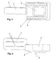
- Figures 5 and 6 show the same end caps as in Figures 3 and 4.
- the Sliding surface has at least one, advantageously a plurality of cleaning grooves (4)
- the purpose of these cleaning grooves is to remove impurities that are on the Have reached the sliding surface, to be removed or collected or removed.
- the Cleaning grooves are dimensioned so that they are sufficiently dirty can absorb until they are brushed out when cleaning the lid.
- the cleaning grooves also have a sufficient depth, which means that Grains of sand or other dirt no further contact with the Counter surface, i.e. the sliding guide. This is a removal of the Contamination without damaging or scratching the sliding guide or the Sliding surface of the lid end head possible. This creates an even surface ensures the sliding guide and thus a uniform abrasion of the sliding surface.
- one can hold the lid head firmly in the flat rod Profile (17) are attached to the fastening part of the lid end head, for example on at least one long side, raised longitudinal stripes (see FIG. 4 and 5, (17)).
- This profile has the task of inaccuracies in the hollow profile of the Lift the flat bar by counter pressure and increases the clamping of the Lid end head in the flat bar.
- At least one stop block is required. Disassembly takes place in that the cylinder (13) moves away from the flat rod in the longitudinal direction, the holder (14) holding the flat end head and pulling it out of the hollow profile. In order to ensure that the flat rod is not pulled along, a stop block (15) blocks the way. Assembly takes place in that the cylinder or piston (13), with the new end cap held by the holder, moves in the direction of the flat rod and thereby pushes the end cap into the hollow profile of the flat rod as far as it will go. In this case, the stop block (16) prevents the flat rod from being pushed away. Rounding of the edges and bevels of the lid end head according to the invention can simplify this process.
Landscapes
- Engineering & Computer Science (AREA)
- Textile Engineering (AREA)
- Preliminary Treatment Of Fibers (AREA)
- Reinforced Plastic Materials (AREA)
Applications Claiming Priority (2)
| Application Number | Priority Date | Filing Date | Title |
|---|---|---|---|
| DE10216067 | 2002-04-11 | ||
| DE10216067A DE10216067A1 (de) | 2002-04-11 | 2002-04-11 | Deckelendkopf aus Polymerwerkstoff |
Publications (2)
| Publication Number | Publication Date |
|---|---|
| EP1352995A1 true EP1352995A1 (fr) | 2003-10-15 |
| EP1352995B1 EP1352995B1 (fr) | 2007-04-25 |
Family
ID=28051258
Family Applications (1)
| Application Number | Title | Priority Date | Filing Date |
|---|---|---|---|
| EP03003518A Expired - Lifetime EP1352995B1 (fr) | 2002-04-11 | 2003-02-15 | Embout en matériau polymère pour chapeau de carde |
Country Status (4)
| Country | Link |
|---|---|
| US (2) | US6842947B2 (fr) |
| EP (1) | EP1352995B1 (fr) |
| CN (1) | CN1450213A (fr) |
| DE (2) | DE10216067A1 (fr) |
Families Citing this family (6)
| Publication number | Priority date | Publication date | Assignee | Title |
|---|---|---|---|---|
| DE10358257B4 (de) | 2003-12-11 | 2015-03-12 | Trützschler GmbH & Co Kommanditgesellschaft | Deckelstab für eine Karde, der einen Tragkörper mit einem Garnituraufnahmeteil aufweist, bei dem dem Tragkörper zwei Endkopfteile zugeordnet sind und Verfahren zu seiner Herstellung |
| IN266842B (fr) * | 2005-02-28 | 2015-06-08 | Rieter Ag Maschf | |
| DE102007039707A1 (de) * | 2007-08-22 | 2009-07-30 | Miele & Cie. Kg | Wäschetrockner mit einer Haltevorrichtung |
| CN104088040B (zh) * | 2014-06-11 | 2016-08-24 | 吴江龙升纺织有限公司 | 一种纺织用针座 |
| CN110644103B (zh) * | 2019-10-16 | 2021-06-22 | 晋江恒升染织有限公司 | 一种纺织纱线快速梳理处理方法 |
| CN111607857B (zh) * | 2020-05-22 | 2024-05-28 | 丹阳市永泰纺织有限公司 | 一种用于功能性涤纶混纺纱的快速梳理装置 |
Citations (9)
| Publication number | Priority date | Publication date | Assignee | Title |
|---|---|---|---|---|
| GB921450A (en) * | 1960-03-18 | 1963-03-20 | Tmm Research Ltd | Improvements in textile carding machines |
| US3439386A (en) * | 1966-04-04 | 1969-04-22 | Warner Swasey Co | Plastic faller bar |
| US4270246A (en) * | 1977-09-21 | 1981-06-02 | Trutzschler Gmbh & Co. Kg | Carding flat arrangement |
| US4300266A (en) * | 1978-09-14 | 1981-11-17 | The English Card Clothing Company Limited | Flats for carding machines |
| JPS60139824A (ja) * | 1983-12-27 | 1985-07-24 | Kanai Hiroyuki | 梳綿機用フラツトバ− |
| US5230135A (en) * | 1985-02-15 | 1993-07-27 | Schubert & Salzer Maschinenfabrik Ag | Top bar for carding machine |
| US5473795A (en) * | 1992-04-30 | 1995-12-12 | Trutzschler Gmbh & Co. Kg | Flat bar with gliding pins for carding machine travelling flats |
| US5542154A (en) * | 1993-06-03 | 1996-08-06 | Maschinenfabrik Rieter Ag | Connection between a revolving flat car and a drive belt |
| US6269522B1 (en) * | 1998-11-24 | 2001-08-07 | Graf & Cie Ag | Method of operating a card and a card flat for carrying out the method |
Family Cites Families (18)
| Publication number | Priority date | Publication date | Assignee | Title |
|---|---|---|---|---|
| US3643386A (en) * | 1970-02-19 | 1972-02-22 | John V Grzyll | Abrasive hand apparel |
| US3748792A (en) * | 1970-03-03 | 1973-07-31 | W Lamb | Sanding glove |
| US3789555A (en) * | 1971-01-25 | 1974-02-05 | J Means | Sanding article |
| BE804355A (nl) * | 1973-09-03 | 1974-03-04 | Ferdinand Van Damme & Zonen P | Werkhandschoen |
| US4038787A (en) * | 1976-03-01 | 1977-08-02 | Rb Products Corporation | Abrasive glove |
| FR2397167A1 (fr) * | 1977-07-13 | 1979-02-09 | Foin Ets | Gant de protection |
| GB2078091A (en) * | 1980-06-03 | 1982-01-06 | Early Eileen Vera | Abrasive gloves and the like |
| US4497073A (en) * | 1983-06-29 | 1985-02-05 | Deutsch Warren D | Lacrosse glove |
| DE3505254C2 (de) | 1985-02-15 | 1987-05-07 | Schubert & Salzer Maschinenfabrik Ag, 8070 Ingolstadt | Deckelstab |
| DE3814412A1 (de) * | 1988-04-28 | 1989-11-09 | Truetzschler & Co | Deckelstab fuer karden |
| IT8921641A0 (it) | 1988-09-24 | 1989-09-06 | Truetzschler & Co | Dispositivo su una carda con cappello mobile fatto di sbarra provviste di guarnizioni. |
| US5134746A (en) * | 1989-12-11 | 1992-08-04 | Steven William | Cleaning material |
| US5134809A (en) * | 1990-06-07 | 1992-08-04 | Barney Morton | Sanding apparatus and method of making and using the same |
| DE59408382D1 (de) | 1993-04-16 | 1999-07-15 | Rieter Ag Maschf | Gleitführung für Wanderdeckelkarde |
| US5642527A (en) * | 1996-02-09 | 1997-07-01 | Savage; Craig P. | Glove sander |
| US5885148A (en) * | 1997-09-17 | 1999-03-23 | Vargas; Richard Dean | Flexible finishing glove |
| DE19834893A1 (de) | 1998-08-03 | 2000-02-10 | Rieter Ag Maschf | Karde und Gleitschuh |
| GB9904502D0 (en) * | 1999-02-27 | 1999-04-21 | Boileau Hugh S | Sanding and scouring gloves |
-
2002
- 2002-04-11 DE DE10216067A patent/DE10216067A1/de not_active Withdrawn
-
2003
- 2003-02-15 DE DE50307115T patent/DE50307115D1/de not_active Expired - Fee Related
- 2003-02-15 EP EP03003518A patent/EP1352995B1/fr not_active Expired - Lifetime
- 2003-04-09 US US10/410,521 patent/US6842947B2/en not_active Expired - Fee Related
- 2003-04-10 CN CN03110575A patent/CN1450213A/zh active Pending
-
2004
- 2004-12-03 US US11/004,518 patent/US7055221B2/en not_active Expired - Fee Related
Patent Citations (9)
| Publication number | Priority date | Publication date | Assignee | Title |
|---|---|---|---|---|
| GB921450A (en) * | 1960-03-18 | 1963-03-20 | Tmm Research Ltd | Improvements in textile carding machines |
| US3439386A (en) * | 1966-04-04 | 1969-04-22 | Warner Swasey Co | Plastic faller bar |
| US4270246A (en) * | 1977-09-21 | 1981-06-02 | Trutzschler Gmbh & Co. Kg | Carding flat arrangement |
| US4300266A (en) * | 1978-09-14 | 1981-11-17 | The English Card Clothing Company Limited | Flats for carding machines |
| JPS60139824A (ja) * | 1983-12-27 | 1985-07-24 | Kanai Hiroyuki | 梳綿機用フラツトバ− |
| US5230135A (en) * | 1985-02-15 | 1993-07-27 | Schubert & Salzer Maschinenfabrik Ag | Top bar for carding machine |
| US5473795A (en) * | 1992-04-30 | 1995-12-12 | Trutzschler Gmbh & Co. Kg | Flat bar with gliding pins for carding machine travelling flats |
| US5542154A (en) * | 1993-06-03 | 1996-08-06 | Maschinenfabrik Rieter Ag | Connection between a revolving flat car and a drive belt |
| US6269522B1 (en) * | 1998-11-24 | 2001-08-07 | Graf & Cie Ag | Method of operating a card and a card flat for carrying out the method |
Non-Patent Citations (1)
| Title |
|---|
| PATENT ABSTRACTS OF JAPAN vol. 009, no. 301 (C - 316) 28 November 1985 (1985-11-28) * |
Also Published As
| Publication number | Publication date |
|---|---|
| DE10216067A1 (de) | 2003-10-23 |
| US7055221B2 (en) | 2006-06-06 |
| US20050115026A1 (en) | 2005-06-02 |
| US6842947B2 (en) | 2005-01-18 |
| DE50307115D1 (de) | 2007-06-06 |
| US20030221293A1 (en) | 2003-12-04 |
| EP1352995B1 (fr) | 2007-04-25 |
| CN1450213A (zh) | 2003-10-22 |
Similar Documents
| Publication | Publication Date | Title |
|---|---|---|
| DE4304148B4 (de) | Deckelstab für eine Karde | |
| EP2327510B1 (fr) | Dispositif de finition | |
| DE102009013412A1 (de) | Vorrichtung an einer Karde für Baumwolle, Chemiefasern o. dgl., bei der mindestens ein Deckelstab mit einer Deckelgarnitur vorhanden ist | |
| EP1352995B1 (fr) | Embout en matériau polymère pour chapeau de carde | |
| DE69500895T2 (de) | Bürstenträger für elektrische Maschine | |
| DE102008009815B4 (de) | Rückzugkugel für eine hydrostatische Kolbenmaschine und System aus einer solchen Rückzugskugel und aus einer Vielzahl von Federn | |
| DE69713186T2 (de) | Vorrichtung für Führung und Verbindung des gleitenden Deckels mit dem Antriebsriemen in einer Deckelkarde | |
| DE3438133A1 (de) | Aufloesewalze fuer open-end spinnmaschinen | |
| EP1870498B1 (fr) | Garniture dentaire pour un peigne d'une peigneuse | |
| EP0361219A2 (fr) | Appareil sur une machine de cardage avec chapeaux marchants en forme de barreau comportant une garniture | |
| DE102004033509B4 (de) | Vorrichtung an einer Karde für Baumwolle, Chemiefasern u. dgl., bei der mindestens ein Deckelstab mit einer Deckelgarnitur vorhanden ist | |
| DE3907396C2 (de) | Vorrichtung an einer Karde mit wanderndem Deckel aus mit Garnitur versehenen Deckelstäben | |
| EP0969129A2 (fr) | Segment de peignage pour un peigne circulaire d'une machine textile de peignage | |
| DE10046916A1 (de) | Verfahren und Vorrichtung zum Einstellen des Arbeitsspaltes zwischen den Spitzen von Deckelgarnituren und den Spitzen der Trommelgarnitur einer Karde | |
| DE60302316T2 (de) | Kopf mit Klauen für eine Vorrichtung zum Verkorken von Flaschen mit Korken | |
| DE60109881T2 (de) | System zum Antreiben der Deckel, und Reinigen der Führungselemente der Deckel, in einer Deckelkarde | |
| EP1004692B1 (fr) | Procédé pour faire fonctionner une machine de cardage et chapeaux pour la mise en oeuvre de ce procédé | |
| EP2173504B1 (fr) | Machine à laminer des profilés | |
| DE10358257B4 (de) | Deckelstab für eine Karde, der einen Tragkörper mit einem Garnituraufnahmeteil aufweist, bei dem dem Tragkörper zwei Endkopfteile zugeordnet sind und Verfahren zu seiner Herstellung | |
| DE20320538U1 (de) | Vorrichtung an einer Karde für Baumwolle, Chemiefasern u.dgl., bei der mindestens ein Deckelstab mit einer Deckelgarnitur vorhanden ist | |
| DE10214390A1 (de) | Vorrichtung an einer Karde für Baumwolle, Chemiefasern und dergleichen, bei der mindestens ein Deckelstab mit einer Deckelgarnitur vorhanden ist | |
| DE3732006C1 (en) | Inductor in particular for hardening crankshafts | |
| DE9306323U1 (de) | Deckelstab für eine Karde | |
| DE19834893A1 (de) | Karde und Gleitschuh | |
| CH706358B1 (de) | Deckelstab für eine Karde, welcher Deckelstab einen Tragkörper mit einem Garnituraufnahmeteil und einem Rückenteil aufweist. |
Legal Events
| Date | Code | Title | Description |
|---|---|---|---|
| PUAI | Public reference made under article 153(3) epc to a published international application that has entered the european phase |
Free format text: ORIGINAL CODE: 0009012 |
|
| AK | Designated contracting states |
Kind code of ref document: A1 Designated state(s): AT BE BG CH CY CZ DE DK EE ES FI FR GB GR HU IE IT LI LU MC NL PT SE SI SK TR |
|
| AX | Request for extension of the european patent |
Extension state: AL LT LV MK RO |
|
| 17P | Request for examination filed |
Effective date: 20040415 |
|
| AKX | Designation fees paid |
Designated state(s): CH DE IT LI TR |
|
| GRAP | Despatch of communication of intention to grant a patent |
Free format text: ORIGINAL CODE: EPIDOSNIGR1 |
|
| GRAS | Grant fee paid |
Free format text: ORIGINAL CODE: EPIDOSNIGR3 |
|
| GRAA | (expected) grant |
Free format text: ORIGINAL CODE: 0009210 |
|
| AK | Designated contracting states |
Kind code of ref document: B1 Designated state(s): CH DE IT LI TR |
|
| REG | Reference to a national code |
Ref country code: CH Ref legal event code: EP |
|
| REF | Corresponds to: |
Ref document number: 50307115 Country of ref document: DE Date of ref document: 20070606 Kind code of ref document: P |
|
| PLBE | No opposition filed within time limit |
Free format text: ORIGINAL CODE: 0009261 |
|
| STAA | Information on the status of an ep patent application or granted ep patent |
Free format text: STATUS: NO OPPOSITION FILED WITHIN TIME LIMIT |
|
| 26N | No opposition filed |
Effective date: 20080128 |
|
| PGFP | Annual fee paid to national office [announced via postgrant information from national office to epo] |
Ref country code: CH Payment date: 20080215 Year of fee payment: 6 |
|
| PGFP | Annual fee paid to national office [announced via postgrant information from national office to epo] |
Ref country code: IT Payment date: 20080223 Year of fee payment: 6 Ref country code: DE Payment date: 20080219 Year of fee payment: 6 |
|
| REG | Reference to a national code |
Ref country code: CH Ref legal event code: PL |
|
| PG25 | Lapsed in a contracting state [announced via postgrant information from national office to epo] |
Ref country code: LI Free format text: LAPSE BECAUSE OF NON-PAYMENT OF DUE FEES Effective date: 20090228 Ref country code: CH Free format text: LAPSE BECAUSE OF NON-PAYMENT OF DUE FEES Effective date: 20090228 |
|
| PG25 | Lapsed in a contracting state [announced via postgrant information from national office to epo] |
Ref country code: DE Free format text: LAPSE BECAUSE OF NON-PAYMENT OF DUE FEES Effective date: 20090901 |
|
| PG25 | Lapsed in a contracting state [announced via postgrant information from national office to epo] |
Ref country code: TR Free format text: LAPSE BECAUSE OF FAILURE TO SUBMIT A TRANSLATION OF THE DESCRIPTION OR TO PAY THE FEE WITHIN THE PRESCRIBED TIME-LIMIT Effective date: 20070425 |
|
| PG25 | Lapsed in a contracting state [announced via postgrant information from national office to epo] |
Ref country code: IT Free format text: LAPSE BECAUSE OF NON-PAYMENT OF DUE FEES Effective date: 20090215 |