EP1353023A2 - Floor covering section with locking device - Google Patents
Floor covering section with locking device Download PDFInfo
- Publication number
- EP1353023A2 EP1353023A2 EP02018621A EP02018621A EP1353023A2 EP 1353023 A2 EP1353023 A2 EP 1353023A2 EP 02018621 A EP02018621 A EP 02018621A EP 02018621 A EP02018621 A EP 02018621A EP 1353023 A2 EP1353023 A2 EP 1353023A2
- Authority
- EP
- European Patent Office
- Prior art keywords
- projection
- floor covering
- groove
- connection
- profiles
- Prior art date
- Legal status (The legal status is an assumption and is not a legal conclusion. Google has not performed a legal analysis and makes no representation as to the accuracy of the status listed.)
- Withdrawn
Links
- 238000005253 cladding Methods 0.000 claims 1
- 210000002105 tongue Anatomy 0.000 description 14
- 239000002023 wood Substances 0.000 description 8
- 238000004519 manufacturing process Methods 0.000 description 6
- 238000009408 flooring Methods 0.000 description 5
- 239000003292 glue Substances 0.000 description 5
- 239000012858 resilient material Substances 0.000 description 3
- 239000007787 solid Substances 0.000 description 2
- 230000005540 biological transmission Effects 0.000 description 1
- 238000011109 contamination Methods 0.000 description 1
- 230000002349 favourable effect Effects 0.000 description 1
- 238000000034 method Methods 0.000 description 1
- 239000000758 substrate Substances 0.000 description 1
- 230000008961 swelling Effects 0.000 description 1
Images

Classifications
-
- E—FIXED CONSTRUCTIONS
- E04—BUILDING
- E04F—FINISHING WORK ON BUILDINGS, e.g. STAIRS, FLOORS
- E04F15/00—Flooring
- E04F15/02—Flooring or floor layers composed of a number of similar elements
- E04F15/02005—Construction of joints, e.g. dividing strips
- E04F15/02033—Joints with beveled or recessed upper edges
-
- E—FIXED CONSTRUCTIONS
- E04—BUILDING
- E04F—FINISHING WORK ON BUILDINGS, e.g. STAIRS, FLOORS
- E04F15/00—Flooring
- E04F15/02—Flooring or floor layers composed of a number of similar elements
-
- E—FIXED CONSTRUCTIONS
- E04—BUILDING
- E04F—FINISHING WORK ON BUILDINGS, e.g. STAIRS, FLOORS
- E04F15/00—Flooring
- E04F15/02—Flooring or floor layers composed of a number of similar elements
- E04F15/04—Flooring or floor layers composed of a number of similar elements only of wood or with a top layer of wood, e.g. with wooden or metal connecting members
-
- E—FIXED CONSTRUCTIONS
- E04—BUILDING
- E04F—FINISHING WORK ON BUILDINGS, e.g. STAIRS, FLOORS
- E04F2201/00—Joining sheets or plates or panels
- E04F2201/01—Joining sheets, plates or panels with edges in abutting relationship
- E04F2201/0107—Joining sheets, plates or panels with edges in abutting relationship by moving the sheets, plates or panels substantially in their own plane, perpendicular to the abutting edges
- E04F2201/0115—Joining sheets, plates or panels with edges in abutting relationship by moving the sheets, plates or panels substantially in their own plane, perpendicular to the abutting edges with snap action of the edge connectors
-
- E—FIXED CONSTRUCTIONS
- E04—BUILDING
- E04F—FINISHING WORK ON BUILDINGS, e.g. STAIRS, FLOORS
- E04F2201/00—Joining sheets or plates or panels
- E04F2201/02—Non-undercut connections, e.g. tongue and groove connections
- E04F2201/023—Non-undercut connections, e.g. tongue and groove connections with a continuous tongue or groove
-
- E—FIXED CONSTRUCTIONS
- E04—BUILDING
- E04F—FINISHING WORK ON BUILDINGS, e.g. STAIRS, FLOORS
- E04F2201/00—Joining sheets or plates or panels
- E04F2201/03—Undercut connections, e.g. using undercut tongues or grooves
Definitions
- the invention relates to a floor covering or a wall covering, consisting of several individual profiles forming a cross structure, a tongue and groove connection being provided between adjacent profiles.
- Wood or plastic floor coverings consist of individual profiles, which over or over when laying the floor covering in the area of their longitudinal edges are placed in one another and thus form a cross-link. Only in If necessary, these parquet or laminate floors are solid with the substrate connected, as a rule, the floor coverings are laid floating. There are Suggestions on how to withstand a solid and heavy duty Flooring should be achieved, it is particularly important that this covering composed of individual profiles is easy to lay or is mountable.
- DE-OS 1 918 203 is a plate for floors, walls or the like is known, in which grooves and tongues a dovetail-shaped Have cross section, with the respective plates to Assembling adjacent profiles must be pushed into each other, which proved to be inappropriate due to the space required for this Has.
- the object of the present invention is to create a flooring or wall covering that with little effort is to be installed and a permanently robust cross-connection between the profiles allows.
- This object is achieved in that in the area of the tongue and groove connection latching is provided.
- a tongue and groove connection is used manufactured, additionally secured by a snap connection is.
- Adjacent profiles are thus set one inside the other in such a way that a specified one Snap resistance must be overcome, with little effort can create an optimal connection between the profiles.
- the profiles are precisely aligned in the specified manner positioned to each other.
- a profile that thanks to the invention Training can also have a particularly large length on one long side one groove and one tongue on the other. There is also a on one side Projection and provided on the other a recess, whereby the Interlocking tongue and groove creates a particularly intimate locking connection can be achieved. It is understood that the locking means is quite a game should be designed to remain, especially since the locking means are manufactured too precisely would be associated with unacceptable manufacturing costs.
- the projection of the spring and the recess of the groove is assigned.
- the tongue-and-groove in this way is easier.
- the projection and recess are formed in this way can that the locking connection can also be released again without being destroyed can. Otherwise, the latching connection can also be designed such that no later disassembly of neighboring profiles is possible.
- connection has the advantage that in the context of Dimension and design of the profiles can be specified as neighboring ones Profiles can be arranged to each other. With appropriate positioning of projection or recess this leads to a loosening of the Snap connection when leaving the necessary game accordingly is possible. This is the case, for example, when a clip connection is made between tongue and groove in the form that the locking connection in Area from the lower edge of the spring or the upper edge of the lower leg of the Groove is provided.
- the Projection has the shape of a polygon. It is understood that the In particular, the projection must have a sufficient depth in order to be stable To be able to form locking connection, in which it is prevented that the Can break the lead.
- the projection is in the form of a Has trapezes with obtuse angles.
- the recess should be approximately triangular-shaped the necessary play when assembling the profiles must be designed, so that the projection adapts well to the recess.
- the trapeze has one Form on which the projection at an angle of approximately 130 to 140 ° runs angled, seen from the lower edge of the spring, whereupon a section running parallel to the lower edge.
- Another advantageous embodiment of the invention provides that Snap connection by the spring associated projection and one to form another projection associated with the groove. This is almost a double Snap connection created, namely by a first pair Projection / recess and another pair arranged behind, the Assignment to tongue or groove is reversed. This forms in the area an advantageous locking edge between the projection / recess pair.
- the further projection should be at an angle of approx. 45 ° to the profile be arranged, the projection is in the region of the inside of the lower leg of the groove, partly on the long side of the profile and partly at the top of the lower leg. Instead of an edge in this area the profile is rounded there to improve the locking, where the corresponding further recess has edges or likewise can be rounded.
- Projection / recess From the arrangement of two pairs arranged offset from one another Projection / recess results in that between the projections common locking edge is provided.
- the one that forms the actual locking Locking edge is the common edge of the two projection / recess pairs, so that the projection lies with its back against the recess, due to the arrangement of the locking edge at an angle of approximately 45 ° particularly favorable snapping is effected.
- the locking edge causes Interlocking adjacent profiles that are used to make the connection Sliding from the protrusion into the recess takes place.
- the latching connection in the area of the Tread surface arranged to give a gap between the adjacent profiles is. So on the top of the floor covering remains between neighboring ones Profiles a narrow gap due to the advantageously uniform arrangement the profile is also visually appealing because it works with the invention Profiles and the connection by clipping an improved connection leaves. This not only ensures that actually between neighboring Profiles have an effective connection at all, but it is also given where this occurs, so that it is much more precise, but also easier lets work.
- adjacent profiles mean that the arrangement of the gap gives the possibility of movement between two adjacent profiles if the Snap connection between these should be made or later solved. In this case, the profile part having the spring in the direction of the gap slightly raised, causing the projection to slide into the recess bwz. can be pulled out of this.
- a Support surface is provided, in the area of the spring with its underside the top of the lower leg of the groove rests, making an even better one Transmission of the forces reached and a break of the projection or the Spring is prevented.
- the invention is characterized in particular by the fact that a Flooring or a wall covering made of wood, imitation wood or plastic is created, which consists of individual profiles that during assembly particularly simple, exact, uniform and permanently stable manner with each other can be connected. Neighboring profiles not only point to this a tongue and groove connection, but are also interlocking trained so that it is still durable even after years Connection that sets without additional connecting means such as glue or Fixation on the floor can do because of an advantageously stable cross-connection is created between the individual profiles. The exactness is added, with the adjacent profiles lie against each other, because when manufacturing the Snap connection also results in the positioning of the profiles to each other. So that is the production of particularly long profiles is also possible. Also swelling or shrinking processes can do well through this intimate bond between the profiles are added, if necessary a replacement of individual or multiple profiles is easily possible.
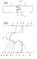
- the latching connection 5 is formed by that assigned to the profile 2 Spring 8 and the groove 9 assigned to the profile 3.
- Fig. 2 shows such a locking connection 5 in more detail Presentation.
- the profile 3 with the spring 8 on it Bottom 13 has a projection 6, which corresponds to a Has recess 7 on the top 14 of the lower leg 15 of the groove 9.
- a recess 19 which corresponds to the projection 12 of the profile 2 is formed.
- This causes a locking edge 11 which is between the respective pair of projection 6 / recess 7 or projection 12 / recess 19 sets and in the area of which both profiles 2, 3 lie against each other.
- a bearing surface 18 can be seen at the tip of the spring 8, in the area thereof there is also contact between the profiles 2, 3.
- the gap 16 between the profiles 2, 3 in the area of the tread surface 25 can also be seen the gap 16 between the profiles 2, 3 in the area of the tread surface 25.
- This gap 16 is in the same position for all of the adjacent profiles and also from constant width, as it were the clip connection between the profiles specifies this distance.
- the depth of the groove 9 exceeds that of the tongue 8, so that a distance remains between the tip 26 of the tongue and the groove base 21.
- the right one is used to create the catch when installing the floor profiles Profile 3 with the spring 8 pushed into the left profile 2 or the groove 9.
- the right profile 3 can be raised at a slight angle with the spring 8 are inserted into the groove, so that the 5 forces to be overcome can be reduced.
- the profiles 2 and 3 abut each other.
- FIG. 3 shows a profile 3 with that on the underside 13 of the spring 8 arranged projection 6.
- This is trapezoidal, d. H.
- the two Legs 27, 28 extend in the form of obtuse angles to the underside 13 the spring, in between is a section 23 running parallel to the underside 13 to recognize.
- the inner leg 28 also forms the locking edge 11.
- At the Projection 6 joins the recess 19, which corresponds to one corresponding projection is formed in the area of the adjacent profile.
- a further projection could be arranged on the upper side 17 of the spring 8, with in connection with the resilient material wood or plastic a particularly intimate locking could be achieved.
- Fig. 4 shows a profile 2 with groove 9 and approximately at a right angle descriptive recess 7, which is the rounded projection 12 is subordinate. It is understood that bevels 20 on such Positions are arranged, in particular for handling during manufacture the locking connection are advantageous.
Landscapes
- Engineering & Computer Science (AREA)
- Architecture (AREA)
- Civil Engineering (AREA)
- Structural Engineering (AREA)
- Life Sciences & Earth Sciences (AREA)
- Wood Science & Technology (AREA)
- Floor Finish (AREA)
- Tires In General (AREA)
Abstract
Description
Die Erfindung betrifft einen Bodenbelag oder eine Wandverkleidung, bestehend aus mehreren, einen Querverband bildenden einzelnen Profilen, wobei zwischen benachbarten Profilen eine Nut-Feder-Verbindung vorgesehen ist.The invention relates to a floor covering or a wall covering, consisting of several individual profiles forming a cross structure, a tongue and groove connection being provided between adjacent profiles.
Bodenbeläge aus Holz oder Kunststoff bestehen aus einzelnen Profilen, welche beim Verlegen des Bodenbelages im Bereich ihrer Längskanten überoder ineinander gesetzt werden und damit einen Querverband bilden. Nur im Bedarfsfall sind diese Parkett- oder Laminatböden fest mit dem Untergrund verbunden, in der Regel werden die Bodenbeläge schwimmend verlegt. Es gibt Vorschläge, wie ein solider und hohen Beanspruchungen standhaltender Bodenbelag erreicht werden soll, wobei es von besonderer Bedeutung ist, dass dieser aus einzelnen Profilen zusammengesetzte Belag leicht verleg- bzw. montierbar ist. So ist aus der DE-OS 1 918 203 eine Platte für Fußböden, Wände oder dergleichen bekannt, bei der Nuten und Federn einen schwalbenschwanzförmigen Querschnitt besitzen, wobei die jeweiligen Platten zum Zusammensetzen benachbarter Profile ineinander geschoben werden müssen, was sich aufgrund des hierfür notwendigen Platzes als unzweckmäßig erwiesen hat. Die Herstellung solcher Profile ist auch viel zu teuer, da eine zu exakte Anpassung der ineinander greifenden Bauteile erforderlich ist. Aus der DE-OS 198 379 77 ist ein Bodenbelag bekannt, welcher eine einfache Nut-Feder-Verbindung aufweist, in deren Bereich Leimmittel eingebracht werden, womit im Zusammen-hang mit einem an den Farbton der Profile angepassten Leimmittel eine Verbindung zwischen benachbarten Profilen erreicht werden soll. Die Verlegung eines solchen Bodenbelags ist allerdings mit dem erheblichen Nachteil verbunden, dass das Aufbringen des Leimmittels einen weiteren aufwendigen Arbeitsschritt darstellt, zumal der Einsatz von Leimmitteln immer mit dem Nachteil von Ver-schmutzungen des Bodenbelags einhergeht.Wood or plastic floor coverings consist of individual profiles, which over or over when laying the floor covering in the area of their longitudinal edges are placed in one another and thus form a cross-link. Only in If necessary, these parquet or laminate floors are solid with the substrate connected, as a rule, the floor coverings are laid floating. There are Suggestions on how to withstand a solid and heavy duty Flooring should be achieved, it is particularly important that this covering composed of individual profiles is easy to lay or is mountable. DE-OS 1 918 203 is a plate for floors, walls or the like is known, in which grooves and tongues a dovetail-shaped Have cross section, with the respective plates to Assembling adjacent profiles must be pushed into each other, which proved to be inappropriate due to the space required for this Has. The production of such profiles is also far too expensive, since it is too exact Adjustment of the interlocking components is required. From the DE-OS 198 379 77 a floor covering is known which has a simple tongue and groove connection has, in the area of which glue is introduced, with which in In connection with a glue adapted to the color of the profiles a connection between adjacent profiles is to be achieved. The Laying such a floor covering is, however, with the considerable disadvantage connected that the application of the glue means another expensive Work step represents, especially since the use of glue always with the disadvantage contamination of the flooring.
Vor diesem Hintergrund stellt sich der vorliegenden Erfindung die Aufgabe, einen Bodenbelag oder eine Wandverkleidung zu schaffen, der mit wenig Aufwand zu montieren ist und einen dauerhaft robusten Querverbund zwischen den Profilen ermöglicht.Against this background, the object of the present invention is to create a flooring or wall covering that with little effort is to be installed and a permanently robust cross-connection between the profiles allows.
Diese Aufgabe wird dadurch gelöst, dass im Bereich der Nut-Feder-Verbindung eine Verrastung vorgesehen ist.This object is achieved in that in the area of the tongue and groove connection latching is provided.
Beim Verlegen des Bodenbelags oder der Wandverkleidung wird eine Nut-Feder-Verbindung hergestellt, die zusätzlich durch eine Rastverbindung gesichert ist. Benachbarte Profile werden also so ineinander gesetzt, dass ein vorgegebener Rastwiderstand überwunden werden muss, wobei sich mit geringem Montageaufwand eine optimale Verbindung zwischen den Profilen herstellen lässt. Gleichzeitig sind die Profile dabei in der vorgegebenen Weise exakt ausgerichtet zueinander positioniert.When laying the flooring or wall covering, a tongue and groove connection is used manufactured, additionally secured by a snap connection is. Adjacent profiles are thus set one inside the other in such a way that a specified one Snap resistance must be overcome, with little effort can create an optimal connection between the profiles. At the same time, the profiles are precisely aligned in the specified manner positioned to each other.
Zweckmäßig ist es, wenn die Verrastung durch mindestens einen Vorsprung und eine korrespondierend zu diesem Vorsprung ausgebildete Ausnehmung gebildet ist. Dazu weist ein Profil, das dank der erfindungsgemäßen Ausbildung auch eine besonders große Länge aufweisen kann, an einer Längsseite eine Nut und an der anderen eine Feder auf. Weiterhin ist an einer Seite ein Vorsprung und an der anderen eine Ausnehmung vorgesehen, wodurch beim Ineinandersetzen von Nut und Feder eine besonders innige Rastverbindung erreicht werden kann. Es versteht sich, dass die Rastmittel durchaus ein Spiel belassend ausgebildet sein sollten, zumal eine zu exakte Fertigung der Rastmittel mit nicht vertretbaren Kosten bei der Herstellung verbunden wäre.It is useful if the locking by at least one Projection and a trained corresponding to this projection Recess is formed. For this purpose, a profile that thanks to the invention Training can also have a particularly large length on one long side one groove and one tongue on the other. There is also a on one side Projection and provided on the other a recess, whereby the Interlocking tongue and groove creates a particularly intimate locking connection can be achieved. It is understood that the locking means is quite a game should be designed to remain, especially since the locking means are manufactured too precisely would be associated with unacceptable manufacturing costs.
Dabei ist insbesondere daran gedacht, dass der Vorsprung der Feder und die Ausnehmung der Nut zugeordnet ist. Neben fertigungstechnischen Aspekten spricht hierfür, dass das Ineinandersetzen von Nut und Feder auf diese Weise einfacher ist. Im Zusammenhang mit dem nachgiebigen Material Holz oder auch Kunststoff ist die für das Zusammensetzen zu überwindende Kraft entsprechend gering. Es versteht sich, dass Vorsprung und Ausnehmung so ausgebildet sein können, dass die Rastverbindung auch zerstörungsfrei wieder gelöst werden kann. Andernfalls kann die Rastverbindung aber auch so ausgebildet sein, dass gerade kein späteres Auseinandernehmen benachbarter Profile möglich ist.It is particularly thought that the projection of the spring and the recess of the groove is assigned. In addition to manufacturing aspects speaks for the fact that the tongue-and-groove in this way is easier. In connection with the resilient material wood or also Plastic is the force to be overcome for assembly low. It goes without saying that the projection and recess are formed in this way can that the locking connection can also be released again without being destroyed can. Otherwise, the latching connection can also be designed such that no later disassembly of neighboring profiles is possible.
Darüber hinaus wird vorgeschlagen, dass der Vorsprung an der Unterseite der Feder und die Ausnehmung an der Oberseite des unteren Schenkels der Nut angeordnet ist. Die Verbindung hat wie erwähnt, den Vorteil, dass im Rahmen der Abmessung und Ausbildung der Profile vorgegeben werden kann, wie benachbarte Profile zueinander angeordnet werden. Bei entsprechender Positionierung von Vorsprung bzw. Ausnehmung führt dies dazu, dass auch ein Lösen der Rastverbindung beim entsprechenden Belassen des hierfür notwendigen Spiels ermöglicht ist. Dies ist beispielsweise der Fall, wenn eine Klippverbindung zwischen Nut und Feder in der Form hergestellt wird, dass die Rastverbindung im Bereich von Unterkante der Feder bzw. der Oberkante des unteren Schenkels der Nut vorgesehen ist.It also suggests that the protrusion on the bottom the tongue and the recess on the top of the lower leg of the groove is arranged. As mentioned, the connection has the advantage that in the context of Dimension and design of the profiles can be specified as neighboring ones Profiles can be arranged to each other. With appropriate positioning of projection or recess this leads to a loosening of the Snap connection when leaving the necessary game accordingly is possible. This is the case, for example, when a clip connection is made between tongue and groove in the form that the locking connection in Area from the lower edge of the spring or the upper edge of the lower leg of the Groove is provided.
Ergänzend dazu ist es auch denkbar, dass ein weiterer Vorsprung an der Oberseite der Feder angeordnet ist, so dass in Folge einer doppelten Verrastung im Zusammenhang mit dem nachgiebigen Material Holz oder auch Kunststoff eine besonders stabile Verbindung gegeben ist.In addition to this, it is also conceivable that a further advantage on the Top of the spring is arranged so that as a result of a double locking in connection with the resilient material wood or plastic particularly stable connection is given.
In Hinblick auf die Form des Vorsprungs wird vorgeschlagen, dass der Vorsprung die Form eines Polygons aufweist. Es versteht sich, dass der Vorsprung insbesondere eine ausreichende Tiefe aufweisen muss, um eine stabile Rastverbindung ausbilden zu können, bei welcher verhindert wird, dass der Vorsprung abbrechen könnte. With regard to the shape of the projection, it is proposed that the Projection has the shape of a polygon. It is understood that the In particular, the projection must have a sufficient depth in order to be stable To be able to form locking connection, in which it is prevented that the Could break the lead.
Dies ist beispielsweise der Fall, wenn der Vorsprung die Form eines Trapezes mit stumpf verlaufenden Winkeln aufweist. Die korrespondierend zu dem Vorsprung ausgebildete Ausnehmung sollte dazu in etwa dreieckig, das notwendige Spiel beim Zusammensetzen der Profile belassend ausgebildet sein, so dass sich der Vorsprung gut der Ausnehmung anpasst. Das Trapez weist eine Form auf, bei der der Vorsprung mit einem Winkel von in etwa 130 bis 140° abgewinkelt verläuft, gesehen von der Unterkante der Feder, woraufhin sich ein parallel zur Unterkante verlaufender Abschnitt anschließt.This is the case, for example, if the projection is in the form of a Has trapezes with obtuse angles. The corresponding to that To this end, the recess should be approximately triangular-shaped the necessary play when assembling the profiles must be designed, so that the projection adapts well to the recess. The trapeze has one Form on which the projection at an angle of approximately 130 to 140 ° runs angled, seen from the lower edge of the spring, whereupon a section running parallel to the lower edge.
Eine weitere vorteilhafte Ausführungsform der Erfindung sieht vor, die Rastverbindung durch den der Feder zugeordneten Vorsprung und einen weiteren, der Nut zugeordneten Vorsprung zu bilden. Damit ist quasi eine doppelte Rastverbindung geschaffen, nämlich durch ein erstes Paar Vorsprung/Ausnehmung und ein weiteres, dahinter angeordnetes Paar, wobei die Zuordnung zu Nut bzw. Feder umgekehrt ist. Dadurch bildet sich im Bereich zwischen den Vorsprung/Ausnehmung-Paar eine vorteilhafte Rastkante.Another advantageous embodiment of the invention provides that Snap connection by the spring associated projection and one to form another projection associated with the groove. This is almost a double Snap connection created, namely by a first pair Projection / recess and another pair arranged behind, the Assignment to tongue or groove is reversed. This forms in the area an advantageous locking edge between the projection / recess pair.
Der weitere Vorsprung sollte dabei in einem Winkel von ca. 45° zum Profil angeordnet sein, der Vorsprung befindet sich im Bereich der Innenseite des unteren Schenkels der Nut, teilweise an der Längsseite des Profils und teilweise an der Oberseite des unteren Schenkels. Anstatt einer Kante in diesem Bereich ist das Profil dort zur Verbesserung der Verrastung abgerundet ausgebildet, wobei die dazu korrespondierende weitere Ausnehmung Kanten aufweist oder ebenfalls abgerundet ausgebildet sein kann.The further projection should be at an angle of approx. 45 ° to the profile be arranged, the projection is in the region of the inside of the lower leg of the groove, partly on the long side of the profile and partly at the top of the lower leg. Instead of an edge in this area the profile is rounded there to improve the locking, where the corresponding further recess has edges or likewise can be rounded.
Aus der Anordnung zweier versetzt zueinander angeordneter Paare Vorsprung/Ausnehmung ergibt sich, dass zwischen den Vorsprüngen eine gemeinsame Rastkante vorgesehen ist. Die die eigentliche Verrastung bildende Rastkante ist die gemeinsame Kante der beiden Vorsprung/Ausnehmung-Paare, so dass hier der Vorsprung mit seiner Rückseite an der Ausnehmung anliegt, wobei aufgrund der Anordnung der Rastkante in einem Winkel von ca. 45° ein besonders günstiges Einrasten bewirkt wird. Die Rastkante bewirkt beim Ineinandersetzen benachbarter Profile, dass zur Herstellung der Verbindung ein Gleiten vom Vorsprung in die Ausnehmung stattfindet.From the arrangement of two pairs arranged offset from one another Projection / recess results in that between the projections common locking edge is provided. The one that forms the actual locking Locking edge is the common edge of the two projection / recess pairs, so that the projection lies with its back against the recess, due to the arrangement of the locking edge at an angle of approximately 45 ° particularly favorable snapping is effected. The locking edge causes Interlocking adjacent profiles that are used to make the connection Sliding from the protrusion into the recess takes place.
Weiterhin ist vorgesehen, dass die Rastverbindung im Bereich der Trittfläche einen Spalt zwischen den benachbarten Profilen ergebend angeordnet ist. An der Oberseite des Bodenbelags verbleibt also zwischen benachbarten Profilen ein schmaler Spalt, der aufgrund der vorteilhaft gleichmäßigen Anordnung der Profile auch optisch ansprechend wirkt, weil sich mit den erfindungsgemäßen Profilen und der Verbindung durch Klippen eine verbesserte Verbindung herstellen lässt. Damit ist nicht nur gewährleistet, dass tatsächlich zwischen benachbarten Profilen überhaupt eine wirksame Verbindung besteht, sondern es ist auch vorgegeben, wo sich diese einstellt, so dass sich viel exakter, aber auch einfacher arbeiten lässt. Neben Vorteilen bei der Montage, also beim ineinander Setzen benachbarter Profile kommt hinzu, dass die Anordnung des Spaltes die Bewegungsmöglichkeit zwischen zwei benachbarten Profilen ermöglicht, wenn die Rastverbindung zwischen diesen hergestellt oder auch später gelöst werden soll. In diesem Fall wird das die Feder aufweisende Profilteil in Richtung des Spaltes leicht angehoben, wodurch der Vorsprung in die Ausnehmung hinein geschoben bwz. aus dieser heraus gezogen werden kann.It is also provided that the latching connection in the area of the Tread surface arranged to give a gap between the adjacent profiles is. So on the top of the floor covering remains between neighboring ones Profiles a narrow gap due to the advantageously uniform arrangement the profile is also visually appealing because it works with the invention Profiles and the connection by clipping an improved connection leaves. This not only ensures that actually between neighboring Profiles have an effective connection at all, but it is also given where this occurs, so that it is much more precise, but also easier lets work. In addition to advantages in assembly, i.e. when nesting In addition, adjacent profiles mean that the arrangement of the gap gives the possibility of movement between two adjacent profiles if the Snap connection between these should be made or later solved. In this case, the profile part having the spring in the direction of the gap slightly raised, causing the projection to slide into the recess bwz. can be pulled out of this.
Hinsichtlich des Stoßes wird vorgeschlagen, dass vor dem Vorsprung eine Auflagerfläche vorgesehen ist, in deren Bereich die Feder mit ihrer Unterseite auf der Oberseite des unteren Schenkels der Nut aufliegt, womit ein noch bessere Übertragung der Kräfte erreicht und ein Abbrechen des Vorsprungs bzw. der Feder verhindert wird.With regard to the impact, it is proposed that a Support surface is provided, in the area of the spring with its underside the top of the lower leg of the groove rests, making an even better one Transmission of the forces reached and a break of the projection or the Spring is prevented.
Die Erfindung zeichnet sich insbesondere dadurch aus, dass ein Bodenbelag oder auch eine Wandverkleidung aus Holz, Holzimitat oder Kunststoff geschaffen ist, welcher aus Einzelprofilen besteht, die bei der Montage auf besonders einfache, exakte, gleichmäßige und dauerhaft stabile Weise miteinander verbunden werden können. Benachbarte Profile weisen dazu nicht nur eine Nut-Feder-Verbindung auf, sondern sind zusätzlich ineinander verrastend ausgebildet, so dass sich eine auch nach Jahren noch dauerhaft belastbare Verbindung einstellt, die ohne zusätzliche Verbindungsmittel wie Kleber oder Fixierung am Boden auskommen kann, weil ein vorteilhaft stabiler Querverbund zwischen den einzelnen Profilen geschaffen ist. Dabei kommt die Exaktheit hinzu, mit der benachbarte Profile aneinander liegen, da sich beim Herstellen der Rastverbindung zugleich die Positionierung der Profile zueinander ergibt. Damit ist auch die Fertigung besonders langer Profile möglich. Auch Quell- oder Schwindprozesse können durch diesen innigen Verbund zwischen den Profilen gut aufgenommen werden, wobei nötigenfalls ein Auswechseln einzelner oder mehrerer Profile ohne Weiteres möglich ist.The invention is characterized in particular by the fact that a Flooring or a wall covering made of wood, imitation wood or plastic is created, which consists of individual profiles that during assembly particularly simple, exact, uniform and permanently stable manner with each other can be connected. Neighboring profiles not only point to this a tongue and groove connection, but are also interlocking trained so that it is still durable even after years Connection that sets without additional connecting means such as glue or Fixation on the floor can do because of an advantageously stable cross-connection is created between the individual profiles. The exactness is added, with the adjacent profiles lie against each other, because when manufacturing the Snap connection also results in the positioning of the profiles to each other. So that is the production of particularly long profiles is also possible. Also swelling or shrinking processes can do well through this intimate bond between the profiles are added, if necessary a replacement of individual or multiple profiles is easily possible.
Weitere Einzelheiten und Vorteile des Erfindungsgegenstandes ergeben sich aus der nachfolgenden Beschreibung der zugehörigen Zeichnung, in der ein bevorzugtes Ausführungsbeispiel mit den dazu notwendigen Einzelheiten und Einzelteilen dargestellt ist. Es zeigen:
- Fig. 1 und 2
- eine Rastverbindung
- Fig. 3
- ein Profil mit Feder und
- Fig. 4
- ein Profil mit Nut.
- 1 and 2
- a snap connection
- Fig. 3
- a profile with spring and
- Fig. 4
- a profile with groove.
Fig. 1 zeigt eine als Nut-Feder-Verbindung 4 ausgebildete Verrastung 5
zwischen den benachbarten Profilen 2 und 3. Eine Vielzahl solcher Profile 2, 3
bildet einen Bodenbelag 1 oder eine Wandverkleidung aus Holz, Holzimitat oder
Kunststoff. Die Rastverbindung 5 ist gebildet durch die dem Profil 2 zugeordnete
Feder 8 sowie die dem Profil 3 zugeordnete Nut 9.1 shows a catch 5 designed as a tongue and groove connection 4
between the
Demgegenüber zeigt Fig. 2 eine solche Rastverbindung 5 in detaillierterer
Darstellung. Dabei ist zu erkennen, dass das Profil 3 mit der Feder 8 an seiner
Unterseite 13 einen Vorsprung 6 aufweist, der korrespondierend zu einer
Ausnehmung 7 an der Oberseite 14 des unteren Schenkels 15 der Nut 9 aufweist.
In Stoßrichtung gesehen hinter dem dem Profil 3 zugeordneten Vorsprung 6 ist
eine Ausnehmung 19 zu erkennen, welche korrespondierend zu dem Vorsprung
12 des Profils 2 ausgebildet ist. Dies bewirkt eine Rastkante 11, die sich zwischen
dem jeweiligen Paar Vorsprung 6/Ausnehmung 7 bzw. Vorsprung 12/Ausnehmung
19 einstellt und in deren Bereich beide Profile 2, 3 aneinander liegen. Außerdem
ist eine Auflagerfläche 18 an der Spitze der Feder 8 zu erkennen, in deren Bereich
ebenfalls Kontakt zwischen den Profilen 2, 3 gegeben ist. Zu erkennen sind ferner
der Spalt 16 zwischen den Profilen 2, 3 im Bereich der Trittfläche 25. Dieser Spalt
16 ist für sämtliche der benachbarten Profile an identischer Position und auch von
konstanter Breite, da gewissermaßen die Klipp-Verbindung zwischen den Profilen
diesen Abstand vorgibt. Die Tiefe der Nut 9 übertrifft die der Feder 8, so dass
zwischen der Spitze 26 der Feder und dem Nutgrund 21 ein Abstand verbleibt.
Zum Herstellen der Verrastung bei der Montage der Bodenprofile wird das rechte
Profil 3 mit der Feder 8 in das linke Profil 2 bzw. die Nut 9 hineingeschoben.
Hierbei kann das rechte Profil 3 in einem leichten Winkel angehoben mit der Feder
8 in die Nut eingesetzt werden, so dass die zum Herstellen der Rastverbindung 5
zu überwindenden Kräfte reduziert werden können. Im Bereich der Längskanten
24 am Boden 22 liegen die Profile 2 und 3 aneinander an.In contrast, Fig. 2 shows such a locking connection 5 in more detail
Presentation. It can be seen that the
Fig. 3 zeigt ein Profil 3 mit dem an der Unterseite 13 der Feder 8
angeordneten Vorsprung 6. Dieser ist trapezförmig ausgebildet, d. h. die beiden
Schenkel 27, 28 verlaufen in der Form von stumpfen Winkeln zur Unterseite 13
der Feder, dazwischen ist ein parallel zur Unterseite 13 verlaufender Abschnitt 23
zu erkennen. Der innere Schenkel 28 bildet zugleich die Rastkante 11. An den
Vorsprung 6 schließt sich die Ausnehmung 19 an, die korrespondierend zu einem
entsprechenden Vorsprung im Bereich des benachbarten Profils ausgebildet ist.
An der Oberseite 17 der Feder 8 könnte ein weiterer Vorsprung angeordnet sein,
mit dem im Zusammenhang mit dem nachgiebigen Material Holz oder Kunststoff
eine besonders innige Verrastung erreicht werden könnte.3 shows a
Fig. 4 zeigt ein Profil 2 mit Nut 9 und der in etwa einen rechten Winkel
beschreibenden Ausnehmung 7, welcher der abgerundet ausgebildete Vorsprung
12 nachgeordnet ist. Es versteht sich, dass des Weiteren Fasen 20 an solchen
Stellen angeordnet sind, die insbesondere für die Handhabung bei der Herstellung
der Rastverbindung von Vorteil sind.Fig. 4 shows a
Alle genannten Merkmale , auch die den Zeichnungen allein zu entnehmenden, werden allein und in Kombination als erfindungswesentlich angesehen.All mentioned features, including those of the drawings alone withdrawing, alone and in combination as essential to the invention considered.
Claims (12)
dadurch gekennzeichnet, dass im Bereich der Nut-Feder-Verbindung (4) eine Verrastung (5) vorgesehen ist.Floor covering (1) or wall cladding, consisting of a plurality of individual profiles forming a cross structure, a tongue and groove connection (4) being provided between adjacent profiles (2, 3),
characterized in that a latching (5) is provided in the area of the tongue and groove connection (4).
dadurch gekennzeichnet, dass die Verrastung (5) durch mindestens einen Vorsprung (6) und eine korrespondierend zu diesem Vorsprung ausgebildete Ausnehmung (7) gebildet ist.Floor covering according to claim 1,
characterized in that the latching (5) is formed by at least one projection (6) and a recess (7) formed corresponding to this projection.
dadurch gekennzeichnet, dass der Vorsprung (6) der Feder (8) und die Ausnehmung (7) der Nut (9) zugeordnet ist.Floor covering according to claim 2,
characterized in that the projection (6) is associated with the tongue (8) and the recess (7) with the groove (9).
dadurch gekennzeichnet, dass der Vorsprung (6) an der Unterseite (13) der Feder (8) und die Ausnehmung (7) an der Oberseite (14) des unteren Schenkels (15) der Nut (9) angeordnet ist.Floor covering according to claim 3,
characterized in that the projection (6) on the underside (13) of the tongue (8) and the recess (7) on the top (14) of the lower leg (15) of the groove (9) is arranged.
dadurch gekennzeichnet, dass ein weiterer Vorsprung an der Oberseite (17) der Feder (8) angeordnet ist.Floor covering according to at least one of the preceding claims,
characterized in that a further projection is arranged on the upper side (17) of the spring (8).
dadurch gekennzeichnet, dass der Vorsprung (6) die Form eines Polygons aufweist. Floor covering according to at least one of the preceding claims
characterized in that the projection (6) has the shape of a polygon.
dadurch gekennzeichnet, dass der Vorsprung (6) die Form eines Trapezes mit stumpf verlaufenden Winkeln aufweist.Floor covering according to claim 6,
characterized in that the projection (6) has the shape of a trapezoid with obtuse angles.
dadurch gekennzeichnet, dass die Rastverbindung (5) durch den der Feder (8) zugeordneten Vorsprung (6) und einen weiteren, der Nut (9) zugeordneten Vorsprung (12) gebildet ist.Floor covering according to at least one of the preceding claims,
characterized in that the latching connection (5) is formed by the projection (6) assigned to the tongue (8) and a further projection (12) assigned to the groove (9).
dadurch gekennzeichnet, dass der weitere Vorsprung (12) in einem Winkel von ca. 45° zum Profil angeordnet ist.Floor covering according to claim 10,
characterized in that the further projection (12) is arranged at an angle of approximately 45 ° to the profile.
dadurch gekennzeichnet, dass zwischen den Vorsprüngen (6,12) eine gemeinsame Rastkante (11) vorgesehen ist.Floor covering according to claim 10,
characterized in that a common locking edge (11) is provided between the projections (6, 12).
dadurch gekennzeichnet, dass die Rastverbindung (5) im Bereich der Trittfläche (25) einen Spalt (16) zwischen den benachbarten Profilen (2,3) ergebend angeordnet ist.Floor covering according to at least one of the preceding claims
characterized in that the latching connection (5) is arranged in the region of the tread surface (25) to give a gap (16) between the adjacent profiles (2, 3).
dadurch gekennzeichnet, dass vor dem Vorsprung (6) eine Auflagerfläche (18) vorgesehen ist, in deren Bereich die Feder (8) mit ihrer Unterseite (13) auf der Oberseite (17) des unteren Schenkels (15) der Nut (9) aufliegt.Floor covering according to at least one of the preceding claims,
characterized in that a bearing surface (18) is provided in front of the projection (6), in the area of which the tongue (8) rests with its underside (13) on the top side (17) of the lower leg (15) of the groove (9) ,
Applications Claiming Priority (2)
| Application Number | Priority Date | Filing Date | Title |
|---|---|---|---|
| DE20205538U | 2002-04-10 | ||
| DE20205538U DE20205538U1 (en) | 2002-04-10 | 2002-04-10 | Floor covering profile with latching |
Publications (2)
| Publication Number | Publication Date |
|---|---|
| EP1353023A2 true EP1353023A2 (en) | 2003-10-15 |
| EP1353023A3 EP1353023A3 (en) | 2004-03-31 |
Family
ID=7969860
Family Applications (1)
| Application Number | Title | Priority Date | Filing Date |
|---|---|---|---|
| EP02018621A Withdrawn EP1353023A3 (en) | 2002-04-10 | 2002-08-20 | Floor covering section with locking device |
Country Status (2)
| Country | Link |
|---|---|
| EP (1) | EP1353023A3 (en) |
| DE (1) | DE20205538U1 (en) |
Cited By (6)
| Publication number | Priority date | Publication date | Assignee | Title |
|---|---|---|---|---|
| EP2407289A1 (en) * | 2004-01-13 | 2012-01-18 | Välinge Innovation AB | Floor covering |
| US9970199B2 (en) | 2003-12-02 | 2018-05-15 | Valinge Innovation Ab | Floorboard, system and method for forming a flooring, and a flooring formed thereof |
| US10138637B2 (en) | 2004-01-13 | 2018-11-27 | Valinge Innovation Ab | Floor covering and locking systems |
| US10801213B2 (en) | 2018-01-10 | 2020-10-13 | Valinge Innovation Ab | Subfloor joint |
| US11578495B2 (en) | 2018-12-05 | 2023-02-14 | Valinge Innovation Ab | Subfloor joint |
| US12195964B2 (en) * | 2020-08-24 | 2025-01-14 | Huber Engineered Woods Llc | Tongue-and-groove panel for improved interpanel fit |
Families Citing this family (1)
| Publication number | Priority date | Publication date | Assignee | Title |
|---|---|---|---|---|
| DE102007061035A1 (en) * | 2007-12-18 | 2009-06-25 | Kaindl Flooring Gmbh | Cladding panel and cladding therefrom |
Citations (2)
| Publication number | Priority date | Publication date | Assignee | Title |
|---|---|---|---|---|
| DE1918203A1 (en) | 1969-04-10 | 1970-10-15 | Johannes Lange | Plate for floors, walls or the like. |
| DE19837977A1 (en) | 1998-08-21 | 2000-02-24 | Michael Stanulla | Laying of laminated floor coverings or parquet with tongued and grooved jointing is completed by sympathetically-colored gap-filling adhesive, to take up tolerances and any subsequent movement |
Family Cites Families (4)
| Publication number | Priority date | Publication date | Assignee | Title |
|---|---|---|---|---|
| US4095913A (en) * | 1976-06-11 | 1978-06-20 | Nils Ingvar Pettersson | Tongue and groove joint |
| US6588166B2 (en) * | 1995-03-07 | 2003-07-08 | Pergo (Europe) Ab | Flooring panel or wall panel and use thereof |
| DE10001248A1 (en) * | 2000-01-14 | 2001-07-19 | Kunnemeyer Hornitex | Profile for releasable connection of floorboards has tongue and groove connection closing in horizontal and vertical directions |
| MD2287C2 (en) * | 2000-03-07 | 2004-06-30 | Е.Ф.П. ФЛОР ПРОДАКТС Фюсбёден Гм0 | Panel, in particular floor panel |
-
2002
- 2002-04-10 DE DE20205538U patent/DE20205538U1/en not_active Expired - Lifetime
- 2002-08-20 EP EP02018621A patent/EP1353023A3/en not_active Withdrawn
Patent Citations (2)
| Publication number | Priority date | Publication date | Assignee | Title |
|---|---|---|---|---|
| DE1918203A1 (en) | 1969-04-10 | 1970-10-15 | Johannes Lange | Plate for floors, walls or the like. |
| DE19837977A1 (en) | 1998-08-21 | 2000-02-24 | Michael Stanulla | Laying of laminated floor coverings or parquet with tongued and grooved jointing is completed by sympathetically-colored gap-filling adhesive, to take up tolerances and any subsequent movement |
Cited By (8)
| Publication number | Priority date | Publication date | Assignee | Title |
|---|---|---|---|---|
| US9970199B2 (en) | 2003-12-02 | 2018-05-15 | Valinge Innovation Ab | Floorboard, system and method for forming a flooring, and a flooring formed thereof |
| EP2407289A1 (en) * | 2004-01-13 | 2012-01-18 | Välinge Innovation AB | Floor covering |
| US10138637B2 (en) | 2004-01-13 | 2018-11-27 | Valinge Innovation Ab | Floor covering and locking systems |
| US10801213B2 (en) | 2018-01-10 | 2020-10-13 | Valinge Innovation Ab | Subfloor joint |
| US10941578B2 (en) | 2018-01-10 | 2021-03-09 | Valinge Innovation Ab | Subfloor joint |
| US11578495B2 (en) | 2018-12-05 | 2023-02-14 | Valinge Innovation Ab | Subfloor joint |
| US12116787B2 (en) | 2018-12-05 | 2024-10-15 | Välinge Innovation AB | Subfloor joint |
| US12195964B2 (en) * | 2020-08-24 | 2025-01-14 | Huber Engineered Woods Llc | Tongue-and-groove panel for improved interpanel fit |
Also Published As
| Publication number | Publication date |
|---|---|
| EP1353023A3 (en) | 2004-03-31 |
| DE20205538U1 (en) | 2002-07-04 |
Similar Documents
| Publication | Publication Date | Title |
|---|---|---|
| DE102009034902B4 (en) | Surface made of mechanically interconnectable panels | |
| DE102004028757B4 (en) | Panel element for floor, wall and / or ceiling installation and method for laying a covering, in particular a floor, wall and / or ceiling covering | |
| DE102008003550B4 (en) | Device and method for locking two floor panels | |
| WO2008122479A1 (en) | Floor, wall, or ceiling panels and method for the connection of said panels | |
| DE202012104530U1 (en) | Set of panels with clip | |
| DE102006057491A1 (en) | Panel and flooring | |
| WO2009021487A1 (en) | Connection | |
| EP1490566A1 (en) | Panel and interlocking system for panels | |
| EP2189589B1 (en) | Wood panel assembly and wood panel for this assembly | |
| EP1380710A2 (en) | Flooring panel and method of laying a flooring panel | |
| EP1900889A2 (en) | Flooring panel | |
| DE202007000310U1 (en) | Panel and flooring | |
| DE10057901C2 (en) | Panel, especially floor panel | |
| DE20205538U1 (en) | Floor covering profile with latching | |
| DE102008003117B4 (en) | Device for locking two building panels | |
| DE102011110071A1 (en) | Method for laying and connecting building panels and locking device for building panels | |
| DE202008005295U1 (en) | connection | |
| DE102007030750B4 (en) | connection | |
| EP1700966A1 (en) | Flat dowel for securing adjacent wooden planks | |
| EP2206853A2 (en) | Floor element with connection elements | |
| DE10253236B4 (en) | Floor panel and method for laying a floor panel | |
| DE102016124988A1 (en) | Hardware for the installation of decking | |
| EP2594704B1 (en) | Assembly of massive wood strips | |
| DE202010007198U1 (en) | Floorboard laying system | |
| DE102011120118B4 (en) | fitting |
Legal Events
| Date | Code | Title | Description |
|---|---|---|---|
| PUAI | Public reference made under article 153(3) epc to a published international application that has entered the european phase |
Free format text: ORIGINAL CODE: 0009012 |
|
| AK | Designated contracting states |
Kind code of ref document: A2 Designated state(s): AT BE BG CH CY CZ DE DK EE ES FI FR GB GR IE IT LI LU MC NL PT SE SK TR |
|
| AX | Request for extension of the european patent |
Extension state: AL LT LV MK RO SI |
|
| PUAL | Search report despatched |
Free format text: ORIGINAL CODE: 0009013 |
|
| AK | Designated contracting states |
Kind code of ref document: A3 Designated state(s): AT BE BG CH CY CZ DE DK EE ES FI FR GB GR IE IT LI LU MC NL PT SE SK TR |
|
| AX | Request for extension of the european patent |
Extension state: AL LT LV MK RO SI |
|
| RIC1 | Information provided on ipc code assigned before grant |
Ipc: 7E 04F 15/04 A |
|
| AKX | Designation fees paid |
Designated state(s): AT BE BG CH CY CZ DE DK EE ES FI FR GB GR IE IT LI LU MC NL PT SE SK TR |
|
| AXX | Extension fees paid |
Extension state: RO Payment date: 20020820 |
|
| STAA | Information on the status of an ep patent application or granted ep patent |
Free format text: STATUS: THE APPLICATION IS DEEMED TO BE WITHDRAWN |
|
| 18D | Application deemed to be withdrawn |
Effective date: 20041001 |