EP1353023A2 - Profilé de revêtement de sol avec dispositif de verrouillage - Google Patents
Profilé de revêtement de sol avec dispositif de verrouillage Download PDFInfo
- Publication number
- EP1353023A2 EP1353023A2 EP02018621A EP02018621A EP1353023A2 EP 1353023 A2 EP1353023 A2 EP 1353023A2 EP 02018621 A EP02018621 A EP 02018621A EP 02018621 A EP02018621 A EP 02018621A EP 1353023 A2 EP1353023 A2 EP 1353023A2
- Authority
- EP
- European Patent Office
- Prior art keywords
- projection
- floor covering
- groove
- connection
- profiles
- Prior art date
- Legal status (The legal status is an assumption and is not a legal conclusion. Google has not performed a legal analysis and makes no representation as to the accuracy of the status listed.)
- Withdrawn
Links
- 238000005253 cladding Methods 0.000 claims 1
- 210000002105 tongue Anatomy 0.000 description 14
- 239000002023 wood Substances 0.000 description 8
- 238000004519 manufacturing process Methods 0.000 description 6
- 238000009408 flooring Methods 0.000 description 5
- 239000003292 glue Substances 0.000 description 5
- 239000012858 resilient material Substances 0.000 description 3
- 239000007787 solid Substances 0.000 description 2
- 230000005540 biological transmission Effects 0.000 description 1
- 238000011109 contamination Methods 0.000 description 1
- 230000002349 favourable effect Effects 0.000 description 1
- 238000000034 method Methods 0.000 description 1
- 239000000758 substrate Substances 0.000 description 1
- 230000008961 swelling Effects 0.000 description 1
Images

Classifications
-
- E—FIXED CONSTRUCTIONS
- E04—BUILDING
- E04F—FINISHING WORK ON BUILDINGS, e.g. STAIRS, FLOORS
- E04F15/00—Flooring
- E04F15/02—Flooring or floor layers composed of a number of similar elements
- E04F15/02005—Construction of joints, e.g. dividing strips
- E04F15/02033—Joints with beveled or recessed upper edges
-
- E—FIXED CONSTRUCTIONS
- E04—BUILDING
- E04F—FINISHING WORK ON BUILDINGS, e.g. STAIRS, FLOORS
- E04F15/00—Flooring
- E04F15/02—Flooring or floor layers composed of a number of similar elements
-
- E—FIXED CONSTRUCTIONS
- E04—BUILDING
- E04F—FINISHING WORK ON BUILDINGS, e.g. STAIRS, FLOORS
- E04F15/00—Flooring
- E04F15/02—Flooring or floor layers composed of a number of similar elements
- E04F15/04—Flooring or floor layers composed of a number of similar elements only of wood or with a top layer of wood, e.g. with wooden or metal connecting members
-
- E—FIXED CONSTRUCTIONS
- E04—BUILDING
- E04F—FINISHING WORK ON BUILDINGS, e.g. STAIRS, FLOORS
- E04F2201/00—Joining sheets or plates or panels
- E04F2201/01—Joining sheets, plates or panels with edges in abutting relationship
- E04F2201/0107—Joining sheets, plates or panels with edges in abutting relationship by moving the sheets, plates or panels substantially in their own plane, perpendicular to the abutting edges
- E04F2201/0115—Joining sheets, plates or panels with edges in abutting relationship by moving the sheets, plates or panels substantially in their own plane, perpendicular to the abutting edges with snap action of the edge connectors
-
- E—FIXED CONSTRUCTIONS
- E04—BUILDING
- E04F—FINISHING WORK ON BUILDINGS, e.g. STAIRS, FLOORS
- E04F2201/00—Joining sheets or plates or panels
- E04F2201/02—Non-undercut connections, e.g. tongue and groove connections
- E04F2201/023—Non-undercut connections, e.g. tongue and groove connections with a continuous tongue or groove
-
- E—FIXED CONSTRUCTIONS
- E04—BUILDING
- E04F—FINISHING WORK ON BUILDINGS, e.g. STAIRS, FLOORS
- E04F2201/00—Joining sheets or plates or panels
- E04F2201/03—Undercut connections, e.g. using undercut tongues or grooves
Definitions
- the invention relates to a floor covering or a wall covering, consisting of several individual profiles forming a cross structure, a tongue and groove connection being provided between adjacent profiles.
- Wood or plastic floor coverings consist of individual profiles, which over or over when laying the floor covering in the area of their longitudinal edges are placed in one another and thus form a cross-link. Only in If necessary, these parquet or laminate floors are solid with the substrate connected, as a rule, the floor coverings are laid floating. There are Suggestions on how to withstand a solid and heavy duty Flooring should be achieved, it is particularly important that this covering composed of individual profiles is easy to lay or is mountable.
- DE-OS 1 918 203 is a plate for floors, walls or the like is known, in which grooves and tongues a dovetail-shaped Have cross section, with the respective plates to Assembling adjacent profiles must be pushed into each other, which proved to be inappropriate due to the space required for this Has.
- the object of the present invention is to create a flooring or wall covering that with little effort is to be installed and a permanently robust cross-connection between the profiles allows.
- This object is achieved in that in the area of the tongue and groove connection latching is provided.
- a tongue and groove connection is used manufactured, additionally secured by a snap connection is.
- Adjacent profiles are thus set one inside the other in such a way that a specified one Snap resistance must be overcome, with little effort can create an optimal connection between the profiles.
- the profiles are precisely aligned in the specified manner positioned to each other.
- a profile that thanks to the invention Training can also have a particularly large length on one long side one groove and one tongue on the other. There is also a on one side Projection and provided on the other a recess, whereby the Interlocking tongue and groove creates a particularly intimate locking connection can be achieved. It is understood that the locking means is quite a game should be designed to remain, especially since the locking means are manufactured too precisely would be associated with unacceptable manufacturing costs.
- the projection of the spring and the recess of the groove is assigned.
- the tongue-and-groove in this way is easier.
- the projection and recess are formed in this way can that the locking connection can also be released again without being destroyed can. Otherwise, the latching connection can also be designed such that no later disassembly of neighboring profiles is possible.
- connection has the advantage that in the context of Dimension and design of the profiles can be specified as neighboring ones Profiles can be arranged to each other. With appropriate positioning of projection or recess this leads to a loosening of the Snap connection when leaving the necessary game accordingly is possible. This is the case, for example, when a clip connection is made between tongue and groove in the form that the locking connection in Area from the lower edge of the spring or the upper edge of the lower leg of the Groove is provided.
- the Projection has the shape of a polygon. It is understood that the In particular, the projection must have a sufficient depth in order to be stable To be able to form locking connection, in which it is prevented that the Can break the lead.
- the projection is in the form of a Has trapezes with obtuse angles.
- the recess should be approximately triangular-shaped the necessary play when assembling the profiles must be designed, so that the projection adapts well to the recess.
- the trapeze has one Form on which the projection at an angle of approximately 130 to 140 ° runs angled, seen from the lower edge of the spring, whereupon a section running parallel to the lower edge.
- Another advantageous embodiment of the invention provides that Snap connection by the spring associated projection and one to form another projection associated with the groove. This is almost a double Snap connection created, namely by a first pair Projection / recess and another pair arranged behind, the Assignment to tongue or groove is reversed. This forms in the area an advantageous locking edge between the projection / recess pair.
- the further projection should be at an angle of approx. 45 ° to the profile be arranged, the projection is in the region of the inside of the lower leg of the groove, partly on the long side of the profile and partly at the top of the lower leg. Instead of an edge in this area the profile is rounded there to improve the locking, where the corresponding further recess has edges or likewise can be rounded.
- Projection / recess From the arrangement of two pairs arranged offset from one another Projection / recess results in that between the projections common locking edge is provided.
- the one that forms the actual locking Locking edge is the common edge of the two projection / recess pairs, so that the projection lies with its back against the recess, due to the arrangement of the locking edge at an angle of approximately 45 ° particularly favorable snapping is effected.
- the locking edge causes Interlocking adjacent profiles that are used to make the connection Sliding from the protrusion into the recess takes place.
- the latching connection in the area of the Tread surface arranged to give a gap between the adjacent profiles is. So on the top of the floor covering remains between neighboring ones Profiles a narrow gap due to the advantageously uniform arrangement the profile is also visually appealing because it works with the invention Profiles and the connection by clipping an improved connection leaves. This not only ensures that actually between neighboring Profiles have an effective connection at all, but it is also given where this occurs, so that it is much more precise, but also easier lets work.
- adjacent profiles mean that the arrangement of the gap gives the possibility of movement between two adjacent profiles if the Snap connection between these should be made or later solved. In this case, the profile part having the spring in the direction of the gap slightly raised, causing the projection to slide into the recess bwz. can be pulled out of this.
- a Support surface is provided, in the area of the spring with its underside the top of the lower leg of the groove rests, making an even better one Transmission of the forces reached and a break of the projection or the Spring is prevented.
- the invention is characterized in particular by the fact that a Flooring or a wall covering made of wood, imitation wood or plastic is created, which consists of individual profiles that during assembly particularly simple, exact, uniform and permanently stable manner with each other can be connected. Neighboring profiles not only point to this a tongue and groove connection, but are also interlocking trained so that it is still durable even after years Connection that sets without additional connecting means such as glue or Fixation on the floor can do because of an advantageously stable cross-connection is created between the individual profiles. The exactness is added, with the adjacent profiles lie against each other, because when manufacturing the Snap connection also results in the positioning of the profiles to each other. So that is the production of particularly long profiles is also possible. Also swelling or shrinking processes can do well through this intimate bond between the profiles are added, if necessary a replacement of individual or multiple profiles is easily possible.
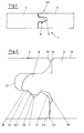
- the latching connection 5 is formed by that assigned to the profile 2 Spring 8 and the groove 9 assigned to the profile 3.
- Fig. 2 shows such a locking connection 5 in more detail Presentation.
- the profile 3 with the spring 8 on it Bottom 13 has a projection 6, which corresponds to a Has recess 7 on the top 14 of the lower leg 15 of the groove 9.
- a recess 19 which corresponds to the projection 12 of the profile 2 is formed.
- This causes a locking edge 11 which is between the respective pair of projection 6 / recess 7 or projection 12 / recess 19 sets and in the area of which both profiles 2, 3 lie against each other.
- a bearing surface 18 can be seen at the tip of the spring 8, in the area thereof there is also contact between the profiles 2, 3.
- the gap 16 between the profiles 2, 3 in the area of the tread surface 25 can also be seen the gap 16 between the profiles 2, 3 in the area of the tread surface 25.
- This gap 16 is in the same position for all of the adjacent profiles and also from constant width, as it were the clip connection between the profiles specifies this distance.
- the depth of the groove 9 exceeds that of the tongue 8, so that a distance remains between the tip 26 of the tongue and the groove base 21.
- the right one is used to create the catch when installing the floor profiles Profile 3 with the spring 8 pushed into the left profile 2 or the groove 9.
- the right profile 3 can be raised at a slight angle with the spring 8 are inserted into the groove, so that the 5 forces to be overcome can be reduced.
- the profiles 2 and 3 abut each other.
- FIG. 3 shows a profile 3 with that on the underside 13 of the spring 8 arranged projection 6.
- This is trapezoidal, d. H.
- the two Legs 27, 28 extend in the form of obtuse angles to the underside 13 the spring, in between is a section 23 running parallel to the underside 13 to recognize.
- the inner leg 28 also forms the locking edge 11.
- At the Projection 6 joins the recess 19, which corresponds to one corresponding projection is formed in the area of the adjacent profile.
- a further projection could be arranged on the upper side 17 of the spring 8, with in connection with the resilient material wood or plastic a particularly intimate locking could be achieved.
- Fig. 4 shows a profile 2 with groove 9 and approximately at a right angle descriptive recess 7, which is the rounded projection 12 is subordinate. It is understood that bevels 20 on such Positions are arranged, in particular for handling during manufacture the locking connection are advantageous.
Landscapes
- Engineering & Computer Science (AREA)
- Architecture (AREA)
- Civil Engineering (AREA)
- Structural Engineering (AREA)
- Life Sciences & Earth Sciences (AREA)
- Wood Science & Technology (AREA)
- Floor Finish (AREA)
- Tires In General (AREA)
Applications Claiming Priority (2)
| Application Number | Priority Date | Filing Date | Title |
|---|---|---|---|
| DE20205538U | 2002-04-10 | ||
| DE20205538U DE20205538U1 (de) | 2002-04-10 | 2002-04-10 | Bodenbelagsprofil mit Verrastung |
Publications (2)
| Publication Number | Publication Date |
|---|---|
| EP1353023A2 true EP1353023A2 (fr) | 2003-10-15 |
| EP1353023A3 EP1353023A3 (fr) | 2004-03-31 |
Family
ID=7969860
Family Applications (1)
| Application Number | Title | Priority Date | Filing Date |
|---|---|---|---|
| EP02018621A Withdrawn EP1353023A3 (fr) | 2002-04-10 | 2002-08-20 | Profilé de revêtement de sol avec dispositif de verrouillage |
Country Status (2)
| Country | Link |
|---|---|
| EP (1) | EP1353023A3 (fr) |
| DE (1) | DE20205538U1 (fr) |
Cited By (6)
| Publication number | Priority date | Publication date | Assignee | Title |
|---|---|---|---|---|
| EP2407289A1 (fr) * | 2004-01-13 | 2012-01-18 | Välinge Innovation AB | Recouvrement de sol |
| US9970199B2 (en) | 2003-12-02 | 2018-05-15 | Valinge Innovation Ab | Floorboard, system and method for forming a flooring, and a flooring formed thereof |
| US10138637B2 (en) | 2004-01-13 | 2018-11-27 | Valinge Innovation Ab | Floor covering and locking systems |
| US10801213B2 (en) | 2018-01-10 | 2020-10-13 | Valinge Innovation Ab | Subfloor joint |
| US11578495B2 (en) | 2018-12-05 | 2023-02-14 | Valinge Innovation Ab | Subfloor joint |
| US12195964B2 (en) * | 2020-08-24 | 2025-01-14 | Huber Engineered Woods Llc | Tongue-and-groove panel for improved interpanel fit |
Families Citing this family (1)
| Publication number | Priority date | Publication date | Assignee | Title |
|---|---|---|---|---|
| DE102007061035A1 (de) * | 2007-12-18 | 2009-06-25 | Kaindl Flooring Gmbh | Verkleidungspaneel und daraus gebildete Verkleidung |
Citations (2)
| Publication number | Priority date | Publication date | Assignee | Title |
|---|---|---|---|---|
| DE1918203A1 (de) | 1969-04-10 | 1970-10-15 | Johannes Lange | Platte fuer Fussboeden,Waende od.dgl. |
| DE19837977A1 (de) | 1998-08-21 | 2000-02-24 | Michael Stanulla | Laminatboden, Fertigparkettboden oder dergleichen, sowie ein Verfahren und Leimmittel zu deren Verlegung |
Family Cites Families (4)
| Publication number | Priority date | Publication date | Assignee | Title |
|---|---|---|---|---|
| US4095913A (en) * | 1976-06-11 | 1978-06-20 | Nils Ingvar Pettersson | Tongue and groove joint |
| US6588166B2 (en) * | 1995-03-07 | 2003-07-08 | Pergo (Europe) Ab | Flooring panel or wall panel and use thereof |
| DE10001248A1 (de) * | 2000-01-14 | 2001-07-19 | Kunnemeyer Hornitex | Profil zum formschlüssigen, leimfreien und wieder lösbaren Verbinden von Fußbodendielen, Paneelen oder ähnl. Bauteilen |
| MD2287C2 (ro) * | 2000-03-07 | 2004-06-30 | Е.Ф.П. ФЛОР ПРОДАКТС Фюсбёден Гм0 | Panou, în special panou pentru pardoseală |
-
2002
- 2002-04-10 DE DE20205538U patent/DE20205538U1/de not_active Expired - Lifetime
- 2002-08-20 EP EP02018621A patent/EP1353023A3/fr not_active Withdrawn
Patent Citations (2)
| Publication number | Priority date | Publication date | Assignee | Title |
|---|---|---|---|---|
| DE1918203A1 (de) | 1969-04-10 | 1970-10-15 | Johannes Lange | Platte fuer Fussboeden,Waende od.dgl. |
| DE19837977A1 (de) | 1998-08-21 | 2000-02-24 | Michael Stanulla | Laminatboden, Fertigparkettboden oder dergleichen, sowie ein Verfahren und Leimmittel zu deren Verlegung |
Cited By (8)
| Publication number | Priority date | Publication date | Assignee | Title |
|---|---|---|---|---|
| US9970199B2 (en) | 2003-12-02 | 2018-05-15 | Valinge Innovation Ab | Floorboard, system and method for forming a flooring, and a flooring formed thereof |
| EP2407289A1 (fr) * | 2004-01-13 | 2012-01-18 | Välinge Innovation AB | Recouvrement de sol |
| US10138637B2 (en) | 2004-01-13 | 2018-11-27 | Valinge Innovation Ab | Floor covering and locking systems |
| US10801213B2 (en) | 2018-01-10 | 2020-10-13 | Valinge Innovation Ab | Subfloor joint |
| US10941578B2 (en) | 2018-01-10 | 2021-03-09 | Valinge Innovation Ab | Subfloor joint |
| US11578495B2 (en) | 2018-12-05 | 2023-02-14 | Valinge Innovation Ab | Subfloor joint |
| US12116787B2 (en) | 2018-12-05 | 2024-10-15 | Välinge Innovation AB | Subfloor joint |
| US12195964B2 (en) * | 2020-08-24 | 2025-01-14 | Huber Engineered Woods Llc | Tongue-and-groove panel for improved interpanel fit |
Also Published As
| Publication number | Publication date |
|---|---|
| EP1353023A3 (fr) | 2004-03-31 |
| DE20205538U1 (de) | 2002-07-04 |
Similar Documents
| Publication | Publication Date | Title |
|---|---|---|
| DE102009034902B4 (de) | Belag aus mechanisch miteinander verbindbaren Paneelen | |
| DE102004028757B4 (de) | Paneelelement zur Boden-, Wand- und/oder Deckenverlegung sowie Verfahren zum Verlegen eines Belages, insbesondere eines Boden-, Wand- und/oder Deckenbelages | |
| DE102008003550B4 (de) | Einrichtung und Verfahren zum Verriegeln zweier Bodenpaneele | |
| WO2008122479A1 (fr) | Panneaux de sol, de mur ou de plafond et procédé de liaison desdits panneaux | |
| DE202012104530U1 (de) | Set aus Paneelen mit Clip | |
| DE102006057491A1 (de) | Paneel sowie Bodenbelag | |
| WO2009021487A1 (fr) | Liaison | |
| EP1490566A1 (fr) | Panneau et systeme de verrouillage pour panneaux | |
| EP2189589B1 (fr) | Agencement de panneau en bois et panneau en bois pour cet agencement | |
| EP1380710A2 (fr) | Panneau de plancher et méthode d'installation d'un panneau de plancher | |
| EP1900889A2 (fr) | Panneau de plancher | |
| DE202007000310U1 (de) | Paneel sowie Bodenbelag | |
| DE10057901C2 (de) | Paneel, insbesondere Fussbodenpaneel | |
| DE20205538U1 (de) | Bodenbelagsprofil mit Verrastung | |
| DE102008003117B4 (de) | Einrichtung zum Verriegeln zweier Bauplatten | |
| DE102011110071A1 (de) | Verfahren zum Verlegen und Verbinden von Gebäudeplatten sowie Verriegelungsvorrichtung für Gebäudeplatten | |
| DE202008005295U1 (de) | Verbindung | |
| DE102007030750B4 (de) | Verbindung | |
| EP1700966A1 (fr) | Cheville plate pour fixer des planches en bois côte à côte | |
| EP2206853A2 (fr) | Elément de sol doté d'éléments de connexion | |
| DE10253236B4 (de) | Fussbodenpaneel und Verfahren zum Verlegen eines Fussbodenpaneels | |
| DE102016124988A1 (de) | Beschlag für das Verlegen von Terrassendielen | |
| EP2594704B1 (fr) | Agencement des lames de bois massif | |
| DE202010007198U1 (de) | Dielenverlegesystem | |
| DE102011120118B4 (de) | Beschlag |
Legal Events
| Date | Code | Title | Description |
|---|---|---|---|
| PUAI | Public reference made under article 153(3) epc to a published international application that has entered the european phase |
Free format text: ORIGINAL CODE: 0009012 |
|
| AK | Designated contracting states |
Kind code of ref document: A2 Designated state(s): AT BE BG CH CY CZ DE DK EE ES FI FR GB GR IE IT LI LU MC NL PT SE SK TR |
|
| AX | Request for extension of the european patent |
Extension state: AL LT LV MK RO SI |
|
| PUAL | Search report despatched |
Free format text: ORIGINAL CODE: 0009013 |
|
| AK | Designated contracting states |
Kind code of ref document: A3 Designated state(s): AT BE BG CH CY CZ DE DK EE ES FI FR GB GR IE IT LI LU MC NL PT SE SK TR |
|
| AX | Request for extension of the european patent |
Extension state: AL LT LV MK RO SI |
|
| RIC1 | Information provided on ipc code assigned before grant |
Ipc: 7E 04F 15/04 A |
|
| AKX | Designation fees paid |
Designated state(s): AT BE BG CH CY CZ DE DK EE ES FI FR GB GR IE IT LI LU MC NL PT SE SK TR |
|
| AXX | Extension fees paid |
Extension state: RO Payment date: 20020820 |
|
| STAA | Information on the status of an ep patent application or granted ep patent |
Free format text: STATUS: THE APPLICATION IS DEEMED TO BE WITHDRAWN |
|
| 18D | Application deemed to be withdrawn |
Effective date: 20041001 |