EP1353029B1 - Serrure - Google Patents
Serrure Download PDFInfo
- Publication number
- EP1353029B1 EP1353029B1 EP03004549A EP03004549A EP1353029B1 EP 1353029 B1 EP1353029 B1 EP 1353029B1 EP 03004549 A EP03004549 A EP 03004549A EP 03004549 A EP03004549 A EP 03004549A EP 1353029 B1 EP1353029 B1 EP 1353029B1
- Authority
- EP
- European Patent Office
- Prior art keywords
- bolt
- lock
- latch
- axis
- hoop
- Prior art date
- Legal status (The legal status is an assumption and is not a legal conclusion. Google has not performed a legal analysis and makes no representation as to the accuracy of the status listed.)
- Expired - Lifetime
Links
Images


Classifications
-
- E—FIXED CONSTRUCTIONS
- E05—LOCKS; KEYS; WINDOW OR DOOR FITTINGS; SAFES
- E05B—LOCKS; ACCESSORIES THEREFOR; HANDCUFFS
- E05B67/00—Padlocks; Details thereof
- E05B67/36—Padlocks with closing means other than shackles ; Removable locks, the lock body itself being the locking element; Padlocks consisting of two separable halves or cooperating with a stud
-
- E—FIXED CONSTRUCTIONS
- E05—LOCKS; KEYS; WINDOW OR DOOR FITTINGS; SAFES
- E05B—LOCKS; ACCESSORIES THEREFOR; HANDCUFFS
- E05B67/00—Padlocks; Details thereof
- E05B67/003—Chain, wire or cable locks
-
- E—FIXED CONSTRUCTIONS
- E05—LOCKS; KEYS; WINDOW OR DOOR FITTINGS; SAFES
- E05B—LOCKS; ACCESSORIES THEREFOR; HANDCUFFS
- E05B67/00—Padlocks; Details thereof
- E05B67/06—Shackles; Arrangement of the shackle
- E05B67/22—Padlocks with sliding shackles, with or without rotary or pivotal movement
- E05B67/24—Padlocks with sliding shackles, with or without rotary or pivotal movement with built- in cylinder locks
Definitions
- the invention relates to a lock, in particular a two-wheel lock, having at least one lock body and a lockable thereto, the lock body has a lock cylinder, with the lock cylinder - at least indirectly - coupled latch and a Klobenhow, into which the block inserted or out of the the block is removable, and wherein the lock cylinder and located in the Klobenage block are arranged along a common lock assembly axis.
- This lock type is thus characterized by a linear arrangement of lock cylinder and clamp, wherein the block is arranged along an extension of the lock cylinder or a rotational actuation axis of the lock cylinder.
- a linear arrangement to couple a arranged at an end face of the lock cylinder rotary drive element with a rotatable carrier cage.
- the Mit supportive hofig forces depending on the rotational position, stored in a storage pan steel balls to a radial entry into the Klobenam or to a radial retreat from the Klobenfact.
- the steel balls for locking the block cooperate with a circumferential groove on the block or soft for unlocking from this circumferential groove back.
- the structure of this castle is undesirable consuming.
- a lock is known in which a lock cylinder drives a rotary latch to a rotational movement, wherein the rotary latch optionally engages laterally in an annular groove of a block.
- US 6,055,832 describes a lock with a lock cylinder, a rotating bolt and a clamp, which are arranged along a common lock assembly axis.
- At least one flat locking section is provided on the part of the block and on the side of the bolt.
- these locking sections cooperate flatly, for example by abutting one another or facing one another. This surface interaction takes place along a transverse plane, in particular perpendicular to the lock arrangement axis.
- This embodiment is based on the finding that a surface interaction of bolt and clamp causes a particularly high tensile stability with respect to an attempt to forcibly remove the locked block from the clamp receptacle. Due to the flat Design of the locking portion of the block and the locking portion of the bolt can be realized in the mutual locking engagement namely a high area coverage. In addition, the bolt and the clamp are claimed only on shearing. This higher tensile stability is particularly noticeable in comparison to known locks in which steel balls rest on the block for locking the block and thus ultimately only a point or linear contact between the block and the balls is realized.
- a direction running transversely to the lock arrangement axis is to be understood as meaning a direction which is perpendicular or substantially perpendicular, in particular oblique to the lock arrangement axis.
- the movement of the bolt between the release position and the locking position takes place along a direction transverse to the lock arrangement axis.
- the surface interaction of the locking portions in the locking position can be realized particularly easily.
- drives namely the lock cylinder a driver part for a rotational movement about the lock assembly axis.
- Such rotational movement has tangential components of movement which are perpendicular to the axis of rotation and thus to the lock assembly axis, and which thus can be easily translated into a latching movement transverse to the lock assembly axis.
- the lock according to the invention can ultimately be realized with a compact design of a driving and locking mechanism.
- the bar is substantially disc-shaped.
- the bolt - for example, as a metal disc - are made in a particularly simple manner, while at the same time have a flat and thus compact design and can be equipped with the required surface locking portion.
- the movement of the bolt between the locking position and the release position can - depending on the coupling with a driver part and depending on leadership within the lock body, for example, as a curved displacement, linear displacement, pivoting, as a rotational movement about the lock assembly axis or as a combination of these types of movement.
- the latch performs a combination of a turning and turning movement within the plane transverse to the lock assembly axis.
- the bolt can be hinged to a hinge device be, which is preferably provided with respect to the lock assembly axis in eccentric arrangement.
- the release recess of the bolt can be formed by a passage opening, ie a circumferentially closed opening.
- a passage opening ie a circumferentially closed opening.
- the release recess is provided on the bolt in an eccentric arrangement.
- the release recess can also be formed by a lateral indentation of the bolt, for example in the manner of a hook.
- the lock has a driver part, via which the bolt is coupled to the lock cylinder.
- the latch on a driver portion on which the driver member engages to drive the latch to move to the locking position and / or in the release position.
- the latch and the driver member are coupled such that rotational movement of the driver member about the latch assembly axis translates into movement of the latch transverse to the latch assembly axis.
- the driver portion of the bolt may for example be formed by an end face of the bolt or - for a slotted guide - an engagement groove, which preferably extends within a transverse plane to the lock assembly axis.
- the said driver part for the coupling with the bolt has at least one driver section, which is in particular designed sickle-shaped.
- a sickle or Crescent shape is particularly suitable for driving the latch to an eccentric pivoting or pivoting motion through cooperation with a catch portion of the latch.
- one or more driving pins, cams or pins may be provided, which engage a driver portion of the bolt.
- driver part and latch can also be configured in reverse, so that ultimately a driver increase of the bolt engages in a driver recess of the driver part.
- the lock on a bracket wherein a kloben neglectedes bracket end connected to the clamp and a lock body side bracket end has a clasping, which is arranged on the lock body such that it engages behind the block or circumferentially engages around, if the block in the Klobenfact is introduced.
- a bracket is provided, which is fastened with one end to the lock body and the free end of which can be selectively locked by means of the clamp on the lock body, for example, to secure an embraced by means of the bracket object against removal.
- the arrangement explained causes a particularly stable connection of the lock body side bracket end with the clamp in the event of a violent tensile load.
- a gripping around the clamp along a closed circumference may be provided, for example by the Umgreifungs Rhein an eyelet of a Gelenkstabbügels or a Starrbügels, or a loop of a Panzerchtbügels or having a cable bracket.
- a gripping behind along an open circumference can take place, so in the manner of a hook.
- the said bracket may be, for example, a cable, a catenary cable, a chain, a rod bracket or a Gelenkstabbügel.
- the clip-side and the lock-body side bracket end are attached to the block or lock body in such a way that the strap ends engage in an opposing pull of the bracket in opposite directions, in particular diametrically opposite to the block, provided the block is in the block receiver.
- the attack tensile load can be particularly effectively absorbed by the block, so that the lock is particularly stable against a violent opening of the bracket.
- the cloverleaf end of the strap is permanently connected to a separate block or formed integrally with a clamp.
- the claw-side bracket end has a clasping device which engages behind the claw in a manner or circumferentially surrounds, as already explained in connection with the lock body side bracket end.
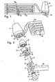
- Figs. 1 to 5 show an inventively designed articulated lock.
- this articulated bar lock has a lock body 11 to which a joint rod 13a is rigidly fastened.
- On the joint rod 13 a successively four joint rods 13 b and a joint rod 13 c are each pivotally and slightly articulated articulated.
- the joint rod 13c is provided with a clamp 15, of which in the closed state of the lock according to FIG. 1, only one mounting base 17 can be seen.
- a lock cylinder housing 19 has the shape of a hollow truncated cone surrounding a lock cylinder receptacle 21, which serves to receive a lock cylinder, not shown in the figures of a conventional structure.
- the lock cylinder housing 19 also has a lateral Fixierfact 23rd
- a driver part 25 essentially has the shape of a hollow cylinder which surrounds a clamp receptacle 27. On an end face of this hollow cylindrical shape, the driver part 25 has a coupling opening 29 for enabling a coupling with said lock cylinder. At the opposite end face, the lateral surface of the driver part 25 is extended along approximately half the circumference to a protruding driver portion 31 which is sickle-shaped in cross-section (see Fig. 4c and 5c). The driver member 25 also has along a the driver portion 31 opposite portion of the outer circumferential surface a rotary clearance recess 33rd
- a latch 35 has the shape of a circular disk with a circular passage opening 37 and a lateral Anschaussparung 39.
- the passage opening 37 is arranged eccentrically with respect to the circular shape of the bolt 35.
- An adjacent to the passage opening 37 surface portion of the bolt 35 serves as a locking portion 41, as will be explained below.
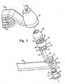
- FIGS. 2 and 3 show that the free end 47 of the joint rod 13c has a fastening opening 49 serving as a gripping device.
- the block 15 has a cylindrical neck neck 51, at one end of the mounting base 17 is formed.
- the other end of the Klobenhalses 51 is formed as a Klobenkopf 53. This is separated from the Klobenhals 51 by a locking recess 55 in the form of a circumferential groove.
- the klobenkopf workede boundary surface of the locking recess 55 forms an annular flat locking portion 57 of the block 15th
- the free end 59 of the joint rod 13 a is inserted into the lock body 11.
- This articulation rod end 59 has a fastening opening 61 serving as encompassing device as well as a fixing opening 63 (compare FIG. 2).
- the lock body 11 is frontally provided with a keyhole 65 (see Fig. 3).
- the lock body 11, the lock cylinder housing 19, the lock cylinder provided therein, the driver part 25, the latch 35, the mounting ring 45 and the clamp 15 are provided in the closed state of the articulated bar lock shown (FIG. 1) for arrangement along a common lock arrangement axis 67.
- the arrangement of the clamp 15 in extension of the provided within the lock cylinder housing 19 lock cylinder characterizes the characteristic linear structure of the lock shown.
- this Schlossanordnurigsachse 67 simultaneously forms the axis of symmetry of the rotationally symmetrical Klobenhalses 51 with the locking recess 55 of the block 15.
- the Schlossan effetivesachse 67 coincides with the Drehbetuschistsachse - not shown in the figures - lock cylinder, and they also corresponds to the axis of rotation of the driver 25, as will be explained below.
- the lock cylinder housing 19 With the locking cylinder not shown in the figures, further the driver part 25 and the bolt 35 along the lock assembly axis 67 within the lock body 11 and there due to the introduced laterally into the lock body 11 hinge rod end 59 of the joint rod 13a caught.
- This joint rod 13a in turn is fixed in the lock body 11 by the fixing pin 43 against a lateral removal from the lock body 11.
- the fixing pin 43 is inserted through the fixing opening 63 of the joint rod 13a, through the Anlenkaussparung 39 of the bolt 35 and through the rotary clearance recess 33 of the driver 25 in the Fixierfact 23 of the lock cylinder housing 19.
- the fixing pin 43 thus also secures the lock cylinder housing 19 against rotation about the lock arrangement axis 67.
- the clamp 15 is fixed to the end 47 of the hinge rod 13c, namely by the Klobenhals 51 is guided through the mounting hole 49 and the mounting base 17 thus abuts against the hinge rod 13c.
- On the opposite side of the hinge rod end 47 of the mounting ring 45 is fixed - for example, by a radial constriction - on the Klobenhals 51, so that the block is caught in the mounting hole 49.
- the mounting base 17 and the fastening ring 45 are spaced apart from each other in such a way that the joint rod 13c is axially displaceable relative to the clamp 15 and / or slightly pivotable with respect to the lock arrangement axis 23. This facilitates the handling of the bracket. If the block 15, as shown in Fig.
- the articulated bar lock shown in FIGS. 1 to 5 functions as follows:
- the clamp 15 can be removed from the clamp receptacle 27 along the lock arrangement axis 67.
- the hingedly connected joint rods 13a, 13b, 13c can then be guided around or through an object to be secured, for example a bicycle.
- the hinge rod 13c is then guided back to the lock body 11 to insert the clamp 15 along the lock assembly axis 67 into the clamp receiver 27.
- the block 15 is locked in this position, as will be explained below.
- the operation of the articulated bar lock shown thus corresponds substantially to that of, for example, a cable lock, the hinge rods serve as a lock bracket.
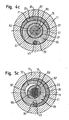
- the latch 35 can be brought into a release position, as shown in Fig. 4a, 4b, 4c.
- this release position the passage opening 37 of the bolt 35 with respect to the Klobenfact 27 of the Mit Converseteils 25 and with respect to the mounting hole 61 of the hinge rod end 59 is aligned such that the Klobenfact 27 extended to a cylindrical cavity and thus released for receiving the block 15 with the Klobenkopf 53 is.
- the bolt 35 is moved perpendicular to the lock assembly axis 67, so that it partially protrudes into the Klobenage 27 and its axial extension and thus also in the locking recess 55 of the block 15 engages (see Fig. 5a, 5b, 5c). This transfer of the bolt 35 in the locking position is done as follows:
- the lock cylinder is rotationally actuated.
- a rotary drive member of the lock cylinder which engages in the coupling opening 29 of the driver 25, is rotated about the lock assembly axis 67.
- the driver member 25 is rotatably supported, namely by the end faces of the driver 25 on the lock cylinder housing 19 and the hinge rod end 59 and the outer circumferential surface of the driver 25 on the inner surface of the Rest against the lock body 11. This rotational actuation of the driver 15 is not hindered by the fixing pin 43, since this is within the rotary clearance recess 33.
- the driver part 25 transmits this rotational movement to the bolt 35 in such a way that it performs a curve / rotational movement within a plane perpendicular to the lock arrangement axis 67.
- a portion of the peripheral end face of the disk-shaped bolt 35 is provided as a driver portion 71, with which cooperates the inner peripheral side of the crescent-shaped cam portion 31 of the driver part 25.
- the latch 35 is movably mounted within the plane perpendicular to the lock arrangement axis 67.
- the latch 35 is moved to the locking position by the driver member 25 performs a rotation about the lock assembly axis 67, which extends in the clockwise direction with respect to the representation of FIG. 4c and 5c.
- the driver portion 31 of the driver 25 moves along along the driver portion 71 on the outer circumference of the bolt 35 and thereby forces the latch 35 to a locking movement in which the latch 35 pivots counterclockwise about one to the fixing pin 35 and the other from the fixing pin 43 radially away, so that the Anlenkaussparung 39 partially disengaged from the fixing pin 43.
- FIGS. 5a and 5b shows the latching position of the bolt 35 achieved thereby.
- the passage opening 37 of the bolt 35 is now offset with respect to the lock arrangement axis 67 and thus with respect to the block 15.
- the latch 35 engages in a part of the locking recess 55 of the Klobens 15 one.
- the locking portion 41 of the bolt 35 which runs perpendicular to the lock arrangement axis 67, bears against the annular locking portion 57 of the bolt 15 (compare FIGS. 5a and 5b).
- the block 15 is thus secured against removal from the Klobenfact 27.
- the renewed release of the block 15 takes place in the reverse order, namely by the lock cylinder is actuated in the reverse direction of rotation and moves the latch 35 via the driver part 25 back into the release position shown in Fig. 4c.
- a particular advantage of the illustrated locking of the clamp 15 within the clamp receptacle 27 is that in the locking position of the bolt 35 whose locking portion 41 flat with the locking portion 57 of the block 15 cooperates, as shown in Fig. 5a and 5b.
- tensile forces are transmitted uniformly - and not only at points or along contact lines - to the bolt 35 and thus to the lock body 11.
- the articulated bar lock shown has a particularly high tensile stability with respect to an attempt to forcibly remove the clamp 15 along the lock assembly axis 67 of the lock body 11. In such a tensile load of the bolt 35 and the cloche head 53 are only subjected to shearing, so that particularly high tensile forces needed to force a yielding of the bolt 35 or the cloche head 53 by force.
- the surface cooperation of the lock sections 41, 57 can be brought about without requiring any axial clearance along the lock arrangement axis 67 for the clamp 15 is that could simplify the attachment of a riser tool, for example between the mounting ring 45 of the block 15 and the ring receiver 69 of the lock body 11 and therefore undesirable.
- Another particular advantage of the illustrated articulated bar lock consists in the manner of attachment of the joint rods 13a and 13c to the lock body 11 and the block 15. As soon as the block 15 is inserted into the lock body 11 and locked therein, embrace the ends 59, 47 both Joint rods 13a, 13c the Klobenhals 51.
- the joint rod end 47 of the joint rod 13c is namely, as explained, by means of the mounting ring 45 permanently attached to the clamp 15.
- the hinge rod end 59 of the hinge rod 13 a is attached to the lock body 11 in such a manner that the cock neck 51 penetrates the attachment hole 61 when the clamp 15 is inserted into the clamp receiver 27.
- This double encompassing of the block 15 by the joint rods 13a, 13c has the advantage that in the case of an attack tensile load of the lock bars formed by the joint rods 13, 13b and 13c, this load is ultimately transferred mainly to the block 15 and the neck 51, respectively.
- excessive loading of the locking mechanism, in particular of the bolt 35 and the driver part 25 is avoided and prevents corresponding damage to the locking of the articulated bar lock.
- the articulated bar lock shown in FIGS. 1 to 5 is designed such that the articulated rod 13a is fastened to the lock body 11 in the position shown in the figures by means of the fixing pin 43 for a service load in the normal operation of the lock. Only with excessive load on the hinge rod 13a, particularly in attempting to forcefully break or wind the lock bracket formed by the hinge rods 13a, 13b and 13c, the hinge rod 13a may move laterally due to slight bending of the fixing pin 43, so that the boundary surface of the attachment hole 61 comes to rest on the neck of the neck 51 and the further tensile load of the joint rod 13a is transmitted directly to the block 15.
- the bolt 35 may also be composed of a plurality of disc-shaped locking elements, which have the same outline as the bolt 35 shown in the figures and arranged parallel to each other adjacent, in particular are attached to each other. In this way, a reinforced locking arrangement can be formed with an even higher shear stability, wherein the individual locking elements can still be manufactured as stampings according to a simple manufacturing process.
- a positive lock is realized. This means that only by corresponding actuation of the lock cylinder by means of the associated identification means of the latch 35 is moved from the release position to the locking position and vice versa.
- an automatic function may be provided, in which the movement of the bolt 35 from the locking position to the release position by the lock cylinder associated with the identification means is triggered, the movement of the bolt 35 in the locked position, however - without the presence of the identification means - by introducing the clamp 15 can be brought into the Klobenfact 27 against the bias by a spring.
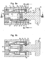
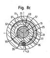
- Fig. 6 to 8 show a mortise lock, which corresponds to the articulated bar lock according to FIGS. 1 to 5 with regard to the construction of its locking mechanism. Similar components as in the illustrated articulated bar lock are marked with the same reference numerals.
- the mortise lock according to FIGS. 6 to 8 - for example as a brake disc lock - has a clamp 15 without hinge rods 13a, 13b, 13c and without any other lock bracket.
- the closure of the lock body 11 takes place at the end facing the clamp 15 by a radially inwardly directed constriction of the ring receptacle 69.
- the lock body 11 is closed by a closing plate 73 which on the lock body 11 by a snap ring 75th is secured.
- Fig. 8a, 8b, 8c show the locking position of the bolt 35, corresponding to Fig. 5a, 5b, 5c.
Landscapes
- Lock And Its Accessories (AREA)
- Vehicle Body Suspensions (AREA)
- Clamps And Clips (AREA)
- Pharmaceuticals Containing Other Organic And Inorganic Compounds (AREA)
- Hydrogenated Pyridines (AREA)
- Actuator (AREA)
Claims (16)
- Serrure, en particulier serrure pour véhicule à deux roues, comprenant au moins un corps de serrure (11) et un plot (15) susceptible d'être verrouillé sur le corps de serrure,
dans lequel le corps de serrure comprend un cylindre de fermeture, un verrou (35) couplé au cylindre de fermeture, et un logement de plot (27),
le plot (15) pouvant être introduit dans le logement de plot (27) ou enlevé hors de celui-ci,
le cylindre de fermeture et le plot (15) qui se trouve dans le logement de plot (27) étant agencés le long d'un axe d'agencement de serrure (67) commun,
le plot (15) comportant un tronçon de verrouillage surfacique (57),
le verrou (35) comportant au moins un évidement de libération (37) et un tronçon de verrouillage surfacique (41), et
dans lequel le verrou (35) peut être déplacé au choix dans une position de verrouillage ou dans une position de libération, telles que dans la position de verrouillage le tronçon de verrouillage (41) du verrou (35) coopère avec le tronçon de verrouillage (57) du plot (15) qui se trouve dans le logement de plot (27) en surface le long d'un plan qui s'étend transversalement à l'axe de verrou (67), et dans la position de libération l'évidement de libération (37) du verrou (35) libère le plot (15) pour un enlèvement hors du logement de plot (27),
caractérisée en ce que
le verrou (35) est articulé de façon excentrée par rapport à l'axe de serrure (67). - Serrure selon la revendication 1,
caractérisée en ce que
le verrou (35) a essentiellement la forme d'un disque,
et/ou
dans la position de verrouillage et/ou dans la position de libération le tronçon de verrouillage surfacique (41) du verrou (35) s'étend transversalement à l'axe de serrure (67),
et/ou
le tronçon de verrouillage surfacique (57) du plot (15) qui se trouve dans le logement de plot (27) s'étend transversalement à l'axe de serrure (67). - Serrure selon l'une des revendications précédentes
caractérisée en ce que
le verrou (35) est déplaçable le long d'un plan qui s'étend transversalement à l'axe de serrure (67),
et/ou
le verrou (35) est mobile le long d'un trajet en courbe, le long d'un trajet rectiligne, en pivotement et/ou en rotation. - Serrure selon l'une des revendications précédentes
caractérisée en ce que
le verrou (35) est articulé sur un moyen d'articulation (43) qui est agencé de manière excentrée par rapport à l'axe de serrure (67),
ledit moyen d'articulation étant formé en particulier par une tige de fixation (43) qui fixe un boîtier de cylindre de fermeture (19) à l'encontre d'une rotation et/ou qui bloque un tronçon en étrier (59) à l'encontre d'un enlèvement. - Serrure selon l'une des revendications précédentes
caractérisée en ce que
l'évidement de libération est formé par une ouverture traversante (37) ou par un creux latéral,
et/ou
le tronçon de verrouillage (41) du verrou (35) est adjacent à l'évidement de libération (37). - Serrure selon l'une des revendications précédentes
caractérisée en ce que
il est prévu une pièce d'entraînement (25) couplée au cylindre de fermeture, et
le verrou (35) comporte un tronçon d'entraînement (71) contre lequel attaque la pièce d'entraînement (25) pour un mouvement du verrou vers la position de verrouillage et/ou vers la position de libération. - Serrure selon la revendication 6,
caractérisée en ce que
la pièce d'entraînement (25) est montée rotative, en particulier par rapport à l'axe de verrou (67),
et/ou
la pièce d'entraînement (25) comporte, pour l'accouplement avec le verrou (35), au moins un tronçon d'entraînement (31) qui est en particulier en forme de croissant, en forme de tenon, ou en forme de tige,
et/ou
le tronçon d'entraînement (71) du verrou (35) est formé par une face frontale ou par une gorge d'engagement, est agencé le long d'un plan qui s'étend transversalement à l'axe de serrure (67) et/ou s'étend en forme de courbe. - Serrure selon l'une des revendications précédentes
caractérisée en ce que
le tronçon de verrouillage (57) du plot (15) est formé par une surface de délimitation d'un évidement de verrouillage (55),
et/ou
le tronçon de verrouillage (57) du plot (15) qui se trouve dans le logement de plot (27) est réalisé à symétrie de révolution par rapport à l'axe de serrure (67). - Serrure selon l'une des revendications précédentes,
caractérisée en ce que
la direction d'introduction du plot, le long de laquelle le plot (15) est introduit dans le logement de plot (27), coïncide au moins sensiblement avec l'axe de serrure (67),
et/ou
en ce qu'un axe de d'actionnement en rotation du cylindre de fermeture coïncide au moins sensiblement avec l'axe de serrure (67). - Serrure selon l'une des revendications précédentes
caractérisée en ce que
le verrou (35) comporte plusieurs éléments de verrou avec le même contour, qui sont agencés au voisinage les uns des autres, et en particulier adjacents les uns aux autres,
et/ou
le verrou (35) est déplaçable par actionnement du cylindre de fermeture vers la position de libération, et
le verrou (35) est déplaçable par actionnement du cylindre de fermeture ou en raison d'une fonction automatique vers la position de verrouillage. - Serrure selon l'une des revendications précédentes
caractérisée en ce que
la serrure comprend un étrier (13a, 13b, 13c),
le plot (15) est relié à une extrémité (47) de l'étrier côté plot, et
une extrémité (59) de l'étrier côté corps de serrure comprend un moyen d'entourement (61) qui est agencé sur le corps de serrure (11) de telle manière qu'il engage le plot (15) par l'arrière ou par la périphérie, lorsque le plot est introduit dans le logement de plot (27). - Serrure selon la revendication 11
caractérisée en ce que
le moyen d'entourement (61) côté corps de serrure est agencé sur le corps de serrure (11) de telle manière que, au moins lorsque l'étrier est soumis à une charge de traction brutale, l'extrémité (59) de l'étrier côté corps de serrure attaque le plot (15), lorsque le plot (15) est introduit dans le logement de plot (27),
et/ou
l'extrémité (59) de l'étrier côté corps de serrure est fixée, vis-à-vis d'un chargement de l'étrier (13a, 13b, 13c) en utilisation, dans un agencement rigide sur le corps de serrure (11),
et/ou
le dispositif d'entourement (61) côté corps de serrure engage le plot (15) par l'arrière ou sur la périphérie à l'intérieur d'un plan qui s'étend transversalement à l'axe de serrure (67) et/ou, lorsque le plot (15) est introduit dans le logement de plot (27), à l'intérieur d'un plan qui s'étend transversalement à un axe longitudinal du plot (15). - Serrure selon l'une des revendications 11 ou 12,
caractérisée en ce que
le plot (15) est fixé de façon permanente à l'extrémité (47) de l'étrier (13a, 13b, 13c) côté plot, ladite extrémité (47) de l'étrier côté plot étant de préférence capable de translation et/ou de rotation par rapport au plot (15), ou en ce que le plot (15) est conformé d'une seule pièce à l'extrémité (47) de l'étrier côté plot,
et/ou
l'extrémité (47) de l'étrier côté plot comprend un moyen d'entourement (49) qui engage le plot (15) par l'arrière ou par la périphérie, et le moyen d'entourement (49) côté plot engage le plot (15) par l'arrière ou par la périphérie de préférence à l'intérieur d'un plan qui s'étend transversalement à un axe longitudinal du plot et/ou, dans le cas où le plot est introduit dans le logement de plot (27), à l'intérieur d'un plan qui s'étend transversalement à l'axe de serrure (67). - Serrure selon l'une des revendications 11 à 13,
caractérisée en ce que
le plot (15) comprend un socle de fixation (17) et une manchette de fixation (45), en particulier de forme annulaire, entre lesquels l'extrémité (47) de l'étrier côté plot est captive,
dans lequel la manchette de fixation (45) est fixée sur le plot (15), de préférence par un rétrécissement radial,
et/ou
le socle de fixation (17) est réalisé de préférence d'une seule pièce avec le plot (15),
et/ou
la manchette de fixation (45) est réalisée de préférence de telle manière qu'elle forme un blocage à coopération de formes avec un logement de manchette (69) prévu sur le corps de serrure (11), lorsque le plot (15) est introduit dans le logement de plot (27). - Serrure selon l'une des revendications 11 à 14,
caractérisée en ce que
le plot (15) comprend un col (51) qui présente de préférence une forme allongée, en particulier une forme cylindrique, et
le dispositif d'entourement (61) côté corps de serrure engage le col (51) du plot par l'arrière ou sur la périphérie, dans le cas où le plot (15) est introduit dans le logement de plot (27),
et/ou
le plot (15) comprend une tête (53) sur laquelle est prévu le tronçon de verrouillage (57). - Serrure selon l'une des revendications précédentes
caractérisée en ce que
l'étrier comprend un câble, un câble blindé, une chaîne, un étrier rigide, ou un étrier à barres articulées (13a, 13b, 13c).
Applications Claiming Priority (2)
| Application Number | Priority Date | Filing Date | Title |
|---|---|---|---|
| DE10215535 | 2002-04-09 | ||
| DE10215535A DE10215535A1 (de) | 2002-04-09 | 2002-04-09 | Schloss |
Publications (2)
| Publication Number | Publication Date |
|---|---|
| EP1353029A1 EP1353029A1 (fr) | 2003-10-15 |
| EP1353029B1 true EP1353029B1 (fr) | 2006-10-04 |
Family
ID=28051220
Family Applications (1)
| Application Number | Title | Priority Date | Filing Date |
|---|---|---|---|
| EP03004549A Expired - Lifetime EP1353029B1 (fr) | 2002-04-09 | 2003-02-28 | Serrure |
Country Status (4)
| Country | Link |
|---|---|
| EP (1) | EP1353029B1 (fr) |
| AT (1) | ATE341685T1 (fr) |
| DE (2) | DE10215535A1 (fr) |
| ES (1) | ES2269843T3 (fr) |
Families Citing this family (9)
| Publication number | Priority date | Publication date | Assignee | Title |
|---|---|---|---|---|
| DE102004052463A1 (de) * | 2004-10-28 | 2006-05-04 | ABUS August Bremicker Söhne KG | Zweirad-Schloss |
| DE102005063514B4 (de) * | 2005-08-24 | 2010-06-17 | ABUS August Bremicker Söhne KG | Gelenkschloss |
| DE102013210475A1 (de) * | 2013-06-05 | 2014-12-11 | ABUS August Bremicker Söhne KG | Gelenkschloss |
| DE102015112915A1 (de) | 2015-08-06 | 2017-02-09 | Vulcan Sports Co., Ltd. | Einbruchsichere, zusammenklappbare Sperrvorrichtung |
| DE202015104106U1 (de) | 2015-08-06 | 2015-08-18 | Vulcan Sports Co., Ltd. | Einbruchsichere, zusammenklappbare Sperrvorrichtung |
| CN106437342B (zh) * | 2016-08-23 | 2018-08-03 | 浙江中立集团有限公司 | 一种可更换链板的折叠锁 |
| CN109854100A (zh) * | 2019-04-02 | 2019-06-07 | 温州市通用锁具有限公司 | 一种折叠锁 |
| CN110512963B (zh) * | 2019-09-04 | 2024-07-30 | 上海钧正网络科技有限公司 | 一种抗冲击防盗锁板、开关方法及车辆 |
| DE202019105979U1 (de) * | 2019-10-28 | 2021-01-29 | Burg-Wächter Kg | Gelenkschloss |
Family Cites Families (5)
| Publication number | Priority date | Publication date | Assignee | Title |
|---|---|---|---|---|
| US3785183A (en) * | 1972-01-31 | 1974-01-15 | I O Prague Corp | Theft deterrent for office machines, television sets and small factory tools |
| US3991594A (en) * | 1974-12-27 | 1976-11-16 | Goenner Albert O | Anti theft locking system |
| US4075878A (en) * | 1976-06-10 | 1978-02-28 | Best Walter E | Cable lock |
| US6055832A (en) * | 1997-09-16 | 2000-05-02 | Wyers; Philip W. | Locking device |
| US6212918B1 (en) * | 1998-09-24 | 2001-04-10 | Benson Enterprises Incorporated | Locking mechanism for portable valuables |
-
2002
- 2002-04-09 DE DE10215535A patent/DE10215535A1/de not_active Withdrawn
-
2003
- 2003-02-28 AT AT03004549T patent/ATE341685T1/de not_active IP Right Cessation
- 2003-02-28 EP EP03004549A patent/EP1353029B1/fr not_active Expired - Lifetime
- 2003-02-28 ES ES03004549T patent/ES2269843T3/es not_active Expired - Lifetime
- 2003-02-28 DE DE50305226T patent/DE50305226D1/de not_active Expired - Lifetime
Also Published As
| Publication number | Publication date |
|---|---|
| EP1353029A1 (fr) | 2003-10-15 |
| ES2269843T3 (es) | 2007-04-01 |
| DE10215535A1 (de) | 2003-10-23 |
| ATE341685T1 (de) | 2006-10-15 |
| DE50305226D1 (de) | 2006-11-16 |
Similar Documents
| Publication | Publication Date | Title |
|---|---|---|
| EP2019178B1 (fr) | Serrure à barres articulées | |
| EP2020474B1 (fr) | Serrure | |
| EP0476229B1 (fr) | Etuer de serrure avec verrouillage basculant | |
| DE60113404T2 (de) | Schlagfeste Verriegelungseinrichtung mit diebstahlsicherem Zylinderkern | |
| DE69819234T2 (de) | Vorhängeschloss | |
| EP2267256B1 (fr) | Cadenas | |
| EP2261447B1 (fr) | Cadenas | |
| EP3575520B1 (fr) | Cadenas à arceau | |
| DE69408012T2 (de) | Schloss für Notausgang, anpassbar an die Türöffnungsrichtung, mit einer Handhabe auf der einen Seite und eine Möglichkeit zum befristeten Öffnen auf der anderen Seite | |
| EP2868850B1 (fr) | Cadenas | |
| EP3741932B1 (fr) | Verrou d'aiguille à articulation | |
| DE60018954T2 (de) | Türverriegelungssystem für einen container | |
| EP1353029B1 (fr) | Serrure | |
| EP1077174A2 (fr) | Serrure pour frein à disque | |
| EP1416110B1 (fr) | Serrure d'encerclement pour deux roues | |
| EP1548216A2 (fr) | Serrure d'encerclement à anse pivotante et système de verrouillage pour bicyclette | |
| WO2013117255A1 (fr) | Système de fermeture, notamment pour des chaînes de protection pour pneus | |
| EP4306393A1 (fr) | Serrure de cadre | |
| DE69832991T2 (de) | Schubriegelanordnung | |
| DE69204044T2 (de) | Sicherheitsschloss für eine Haustüre oder dgl. | |
| EP3095932B1 (fr) | Serrure a deux roues | |
| EP4098830B1 (fr) | Ancre mural | |
| DE4341622A1 (de) | Sicherungsvorrichtung | |
| EP3913170B1 (fr) | Serrure à cylindre | |
| EP3789570B1 (fr) | Cadenas à étrier annulaire et procédé de montage |
Legal Events
| Date | Code | Title | Description |
|---|---|---|---|
| PUAI | Public reference made under article 153(3) epc to a published international application that has entered the european phase |
Free format text: ORIGINAL CODE: 0009012 |
|
| AK | Designated contracting states |
Kind code of ref document: A1 Designated state(s): AT BE BG CH CY CZ DE DK EE ES FI FR GB GR HU IE IT LI LU MC NL PT SE SI SK TR |
|
| AX | Request for extension of the european patent |
Extension state: AL LT LV MK RO |
|
| 17P | Request for examination filed |
Effective date: 20031119 |
|
| AKX | Designation fees paid |
Designated state(s): AT BE BG CH CY CZ DE DK EE ES FI FR GB GR HU IE IT LI LU MC NL PT SE SI SK TR |
|
| 17Q | First examination report despatched |
Effective date: 20040720 |
|
| GRAP | Despatch of communication of intention to grant a patent |
Free format text: ORIGINAL CODE: EPIDOSNIGR1 |
|
| GRAS | Grant fee paid |
Free format text: ORIGINAL CODE: EPIDOSNIGR3 |
|
| GRAA | (expected) grant |
Free format text: ORIGINAL CODE: 0009210 |
|
| AK | Designated contracting states |
Kind code of ref document: B1 Designated state(s): AT BE BG CH CY CZ DE DK EE ES FI FR GB GR HU IE IT LI LU MC NL PT SE SI SK TR |
|
| PG25 | Lapsed in a contracting state [announced via postgrant information from national office to epo] |
Ref country code: IT Free format text: LAPSE BECAUSE OF FAILURE TO SUBMIT A TRANSLATION OF THE DESCRIPTION OR TO PAY THE FEE WITHIN THE PRESCRIBED TIME-LIMIT;WARNING: LAPSES OF ITALIAN PATENTS WITH EFFECTIVE DATE BEFORE 2007 MAY HAVE OCCURRED AT ANY TIME BEFORE 2007. THE CORRECT EFFECTIVE DATE MAY BE DIFFERENT FROM THE ONE RECORDED. Effective date: 20061004 Ref country code: SK Free format text: LAPSE BECAUSE OF FAILURE TO SUBMIT A TRANSLATION OF THE DESCRIPTION OR TO PAY THE FEE WITHIN THE PRESCRIBED TIME-LIMIT Effective date: 20061004 Ref country code: SI Free format text: LAPSE BECAUSE OF FAILURE TO SUBMIT A TRANSLATION OF THE DESCRIPTION OR TO PAY THE FEE WITHIN THE PRESCRIBED TIME-LIMIT Effective date: 20061004 Ref country code: FI Free format text: LAPSE BECAUSE OF FAILURE TO SUBMIT A TRANSLATION OF THE DESCRIPTION OR TO PAY THE FEE WITHIN THE PRESCRIBED TIME-LIMIT Effective date: 20061004 Ref country code: IE Free format text: LAPSE BECAUSE OF FAILURE TO SUBMIT A TRANSLATION OF THE DESCRIPTION OR TO PAY THE FEE WITHIN THE PRESCRIBED TIME-LIMIT Effective date: 20061004 Ref country code: CZ Free format text: LAPSE BECAUSE OF FAILURE TO SUBMIT A TRANSLATION OF THE DESCRIPTION OR TO PAY THE FEE WITHIN THE PRESCRIBED TIME-LIMIT Effective date: 20061004 |
|
| REG | Reference to a national code |
Ref country code: GB Ref legal event code: FG4D Free format text: NOT ENGLISH |
|
| REG | Reference to a national code |
Ref country code: CH Ref legal event code: EP |
|
| REG | Reference to a national code |
Ref country code: IE Ref legal event code: FG4D Free format text: LANGUAGE OF EP DOCUMENT: GERMAN |
|
| REF | Corresponds to: |
Ref document number: 50305226 Country of ref document: DE Date of ref document: 20061116 Kind code of ref document: P |
|
| GBT | Gb: translation of ep patent filed (gb section 77(6)(a)/1977) |
Effective date: 20061207 |
|
| PG25 | Lapsed in a contracting state [announced via postgrant information from national office to epo] |
Ref country code: BG Free format text: LAPSE BECAUSE OF FAILURE TO SUBMIT A TRANSLATION OF THE DESCRIPTION OR TO PAY THE FEE WITHIN THE PRESCRIBED TIME-LIMIT Effective date: 20070104 Ref country code: DK Free format text: LAPSE BECAUSE OF FAILURE TO SUBMIT A TRANSLATION OF THE DESCRIPTION OR TO PAY THE FEE WITHIN THE PRESCRIBED TIME-LIMIT Effective date: 20070104 |
|
| REG | Reference to a national code |
Ref country code: SE Ref legal event code: TRGR |
|
| PG25 | Lapsed in a contracting state [announced via postgrant information from national office to epo] |
Ref country code: CH Free format text: LAPSE BECAUSE OF NON-PAYMENT OF DUE FEES Effective date: 20070228 Ref country code: LI Free format text: LAPSE BECAUSE OF NON-PAYMENT OF DUE FEES Effective date: 20070228 Ref country code: MC Free format text: LAPSE BECAUSE OF NON-PAYMENT OF DUE FEES Effective date: 20070228 |
|
| PG25 | Lapsed in a contracting state [announced via postgrant information from national office to epo] |
Ref country code: PT Free format text: LAPSE BECAUSE OF FAILURE TO SUBMIT A TRANSLATION OF THE DESCRIPTION OR TO PAY THE FEE WITHIN THE PRESCRIBED TIME-LIMIT Effective date: 20070316 |
|
| REG | Reference to a national code |
Ref country code: ES Ref legal event code: FG2A Ref document number: 2269843 Country of ref document: ES Kind code of ref document: T3 |
|
| ET | Fr: translation filed | ||
| REG | Reference to a national code |
Ref country code: IE Ref legal event code: FD4D |
|
| PLBE | No opposition filed within time limit |
Free format text: ORIGINAL CODE: 0009261 |
|
| STAA | Information on the status of an ep patent application or granted ep patent |
Free format text: STATUS: NO OPPOSITION FILED WITHIN TIME LIMIT |
|
| 26N | No opposition filed |
Effective date: 20070705 |
|
| REG | Reference to a national code |
Ref country code: CH Ref legal event code: PL |
|
| BERE | Be: lapsed |
Owner name: ABUS AUGUST BREMICKER SOHNE K.G. Effective date: 20070228 |
|
| PG25 | Lapsed in a contracting state [announced via postgrant information from national office to epo] |
Ref country code: BE Free format text: LAPSE BECAUSE OF NON-PAYMENT OF DUE FEES Effective date: 20070228 |
|
| PG25 | Lapsed in a contracting state [announced via postgrant information from national office to epo] |
Ref country code: AT Free format text: LAPSE BECAUSE OF NON-PAYMENT OF DUE FEES Effective date: 20070228 |
|
| PG25 | Lapsed in a contracting state [announced via postgrant information from national office to epo] |
Ref country code: EE Free format text: LAPSE BECAUSE OF FAILURE TO SUBMIT A TRANSLATION OF THE DESCRIPTION OR TO PAY THE FEE WITHIN THE PRESCRIBED TIME-LIMIT Effective date: 20061004 |
|
| PG25 | Lapsed in a contracting state [announced via postgrant information from national office to epo] |
Ref country code: LU Free format text: LAPSE BECAUSE OF NON-PAYMENT OF DUE FEES Effective date: 20070228 Ref country code: CY Free format text: LAPSE BECAUSE OF FAILURE TO SUBMIT A TRANSLATION OF THE DESCRIPTION OR TO PAY THE FEE WITHIN THE PRESCRIBED TIME-LIMIT Effective date: 20061004 |
|
| PG25 | Lapsed in a contracting state [announced via postgrant information from national office to epo] |
Ref country code: HU Free format text: LAPSE BECAUSE OF FAILURE TO SUBMIT A TRANSLATION OF THE DESCRIPTION OR TO PAY THE FEE WITHIN THE PRESCRIBED TIME-LIMIT Effective date: 20070405 Ref country code: TR Free format text: LAPSE BECAUSE OF FAILURE TO SUBMIT A TRANSLATION OF THE DESCRIPTION OR TO PAY THE FEE WITHIN THE PRESCRIBED TIME-LIMIT Effective date: 20061004 |
|
| PG25 | Lapsed in a contracting state [announced via postgrant information from national office to epo] |
Ref country code: GR Free format text: LAPSE BECAUSE OF NON-PAYMENT OF DUE FEES Effective date: 20070228 |
|
| REG | Reference to a national code |
Ref country code: FR Ref legal event code: PLFP Year of fee payment: 14 |
|
| REG | Reference to a national code |
Ref country code: FR Ref legal event code: PLFP Year of fee payment: 15 |
|
| REG | Reference to a national code |
Ref country code: FR Ref legal event code: PLFP Year of fee payment: 16 |
|
| PGFP | Annual fee paid to national office [announced via postgrant information from national office to epo] |
Ref country code: NL Payment date: 20190218 Year of fee payment: 17 |
|
| PGFP | Annual fee paid to national office [announced via postgrant information from national office to epo] |
Ref country code: ES Payment date: 20190320 Year of fee payment: 17 Ref country code: GB Payment date: 20190218 Year of fee payment: 17 |
|
| PGFP | Annual fee paid to national office [announced via postgrant information from national office to epo] |
Ref country code: FR Payment date: 20190219 Year of fee payment: 17 Ref country code: SE Payment date: 20190218 Year of fee payment: 17 |
|
| PGFP | Annual fee paid to national office [announced via postgrant information from national office to epo] |
Ref country code: DE Payment date: 20190429 Year of fee payment: 17 |
|
| REG | Reference to a national code |
Ref country code: DE Ref legal event code: R119 Ref document number: 50305226 Country of ref document: DE |
|
| REG | Reference to a national code |
Ref country code: NL Ref legal event code: MM Effective date: 20200301 |
|
| GBPC | Gb: european patent ceased through non-payment of renewal fee |
Effective date: 20200228 |
|
| PG25 | Lapsed in a contracting state [announced via postgrant information from national office to epo] |
Ref country code: NL Free format text: LAPSE BECAUSE OF NON-PAYMENT OF DUE FEES Effective date: 20200301 |
|
| PG25 | Lapsed in a contracting state [announced via postgrant information from national office to epo] |
Ref country code: SE Free format text: LAPSE BECAUSE OF NON-PAYMENT OF DUE FEES Effective date: 20200229 Ref country code: GB Free format text: LAPSE BECAUSE OF NON-PAYMENT OF DUE FEES Effective date: 20200228 Ref country code: FR Free format text: LAPSE BECAUSE OF NON-PAYMENT OF DUE FEES Effective date: 20200229 Ref country code: DE Free format text: LAPSE BECAUSE OF NON-PAYMENT OF DUE FEES Effective date: 20200901 |
|
| REG | Reference to a national code |
Ref country code: ES Ref legal event code: FD2A Effective date: 20210630 |
|
| PG25 | Lapsed in a contracting state [announced via postgrant information from national office to epo] |
Ref country code: ES Free format text: LAPSE BECAUSE OF NON-PAYMENT OF DUE FEES Effective date: 20200301 |