EP1353034B1 - Rahmenkonstruktion einer Schiebetür - Google Patents
Rahmenkonstruktion einer Schiebetür Download PDFInfo
- Publication number
- EP1353034B1 EP1353034B1 EP03405238A EP03405238A EP1353034B1 EP 1353034 B1 EP1353034 B1 EP 1353034B1 EP 03405238 A EP03405238 A EP 03405238A EP 03405238 A EP03405238 A EP 03405238A EP 1353034 B1 EP1353034 B1 EP 1353034B1
- Authority
- EP
- European Patent Office
- Prior art keywords
- frame
- insulating body
- frame part
- accommodating
- main frame
- Prior art date
- Legal status (The legal status is an assumption and is not a legal conclusion. Google has not performed a legal analysis and makes no representation as to the accuracy of the status listed.)
- Expired - Lifetime
Links
Images


Classifications
-
- E—FIXED CONSTRUCTIONS
- E06—DOORS, WINDOWS, SHUTTERS, OR ROLLER BLINDS IN GENERAL; LADDERS
- E06B—FIXED OR MOVABLE CLOSURES FOR OPENINGS IN BUILDINGS, VEHICLES, FENCES OR LIKE ENCLOSURES IN GENERAL, e.g. DOORS, WINDOWS, BLINDS, GATES
- E06B3/00—Window sashes, door leaves, or like elements for closing wall or like openings; Layout of fixed or moving closures, e.g. windows in wall or like openings; Features of rigidly-mounted outer frames relating to the mounting of wing frames
- E06B3/04—Wing frames not characterised by the manner of movement
- E06B3/263—Frames with special provision for insulation
- E06B3/26347—Frames with special provision for insulation specially adapted for sliding doors or windows
Definitions
- the invention relates to a frame construction of a sliding door or sliding window according to the preamble of patent claim 1.
- a frame construction is in EP-A-0'080'870 disclosed.
- a main frame made of aluminum two plastic receiving profiles are arranged for receiving one door leaf each.
- the receiving profile of the sliding door is provided with a carriage, which is slidably guided in the main frame.
- the two receiving profiles are separated by a separating element which projects between the receiving profiles and which is integrally formed on the main frame. This separating element also serves to receive sealing brushes, which rest in a sliding manner on the displaceable receiving profile.
- the main frame is designed to be continuous from outside to inside. Thus, it forms a cold bridge between the outside and inside of the window or the door.
- a construction which has a two-part main frame to avoid such cold bridges.
- the inner and the outer part of the frame are separated by an insulating body.
- the receiving profile of the sliding door is arranged within the outer frame part.
- sealing brushes are arranged on both sides, which rest in a sliding manner on the sliding receiving profile.
- the two frame parts are U-shaped. However, since a leg of the respective outer part protrudes from the cold to the warm area, it comes at this point to condensation.
- the receiving profiles of the insulating glass are not insulated and therefore form a continuous cold bridge.
- EP-A-1'101'894 a frame construction for sliding doors, in which each door is held in an L-shaped inner frame.
- the legs of the L-shaped frame extend in the lower horizontal direction and in a lateral vertical direction.
- the two free sides of the door leaf run in an outer frame, which has in the region of these two sides an inner and an outer frame part, which is separated by an insulating body.
- the windows are held along these two sides in receiving profiles, which are laterally provided with brushes. These inner brushes slide along when moving the door along of the insulation body.
- This construction has the disadvantage that the free window area is limited by the L-shaped inner frame.
- the construction is also only suitable for double-leaf doors and can not be used for multi-leaf doors.
- the construction has a relatively high threshold in the lower region due to the lower insulating body. Since this frame construction has differently constructed sides, it is relatively expensive to manufacture and expensive to assemble.
- the BE 1002537 A3 discloses a frame construction for sliding windows, comprising two interconnected by an insulating body rails.
- the two metal rails consisting of insulating rails project above the rails and serve as a system for seals.
- the sliding doors are each supported on the outer leg, which makes a sunken installation of the sliding door in the floor and of course in the ceiling impossible.
- the two guide rails are only partially isolated from each other and the central web, which separates the two runways from each other, consists of metal and thus forms a cold bridge in the longitudinal direction.
- the frame is formed in three parts, wherein the first, outer and the second inner frame part are completely separated from each other at least along the leadership of the carriage by an insulating body.
- Inner sealing elements are slidably between a receiving profile for a door or window sash and a middle frame part.
- the insulating body forms the third part, in the second case, the middle frame part.
- the inner sealing elements are on the middle frame part held.
- the middle frame part is preferably completely thermally separated from the first and the second frame part.
- the middle frame part is also interrupted by transverse to its longitudinal extent of a further sealing part, preferably a brush.
- the arrangement of the inner sealing elements or the further sealing part prevents cold bridges between the inner and the outer frame part. In addition, the formation of condensation is avoided.
- the frame construction can be formed without threshold in the lower area.
- the free window area is maximized. Since the identical parts for the inner, outer and middle frame parts as well as for the insulating body can be used on all four sides of the frame construction, the production and assembly costs are minimized.
- FIG. 1 shows a sliding door S with a frame structure R, in which a fixed door F and a sliding door T are arranged according to a first embodiment. It is also possible to arrange both door slideable and / or more than two door leaves in insert the sliding door.
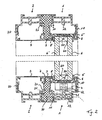
- the inventive frame construction R is in the Figures 2 and 3 better visible.
- the main frame is divided into a first frame part 1 and a second frame part 2.
- the first frame part 1 is here outside, the second frame part 2 arranged inside.
- the arrangement can also be reversed.
- the outer and the inner frame part 1,2 are formed by four profile elements, which each form a longitudinal side of the frame structure.
- the individual profile elements of a frame part 1,2 are identical except for their length. In FIG. 2 the lower and upper profile elements are visible, in FIG. 3 the right and left.
- the following is spoken by frame part 1, 2, wherein in each case a corresponding profile element is meant.
- the first frame part 1 or the corresponding profile element has a substantially U-shaped cross-section.
- an outer leg 10 of the frame part 1 is formed longer than an inner leg 11.
- the two legs are connected via a web 12 with each other.
- the inner frame part 2 or the corresponding profile element is preferably constructed identically as the outer frame part 1. This allows the production costs to be minimized. It is arranged mirror-symmetrically to the first frame part 1, so that its long leg 20 is directed inwards and its short leg 21 outwards.
- an insulating body 7 arranged to prevent cold spots. It is located next to a plane defined by the far-edge or door surface. This insulating body 7 extends on all four sides over the entire length of the frame construction. It is a profile element, which is preferably made of a heat-insulating plastic, foam or other suitable insulation material. He is also preferably formed mirror-symmetrical.
- a head 70 which tapers towards the center of the insulating body towards a neck 71.
- this end is located at the top, bottom, right or left.
- the short legs 11, 21 of the inner and outer frame part 1, 2 have a matching shape, so that they are held in a form-fitting manner on the insulating body 7.
- the positive connection increases the stability. In this case, these short legs 11, 21 preferably extend at most up to the average height of the insulating body. 7
- a middle frame part 3 of the main frame is attached. This too is preferably symmetrical. It also has a substantially U-shaped cross-section, wherein its web is extended on both sides and projects outwardly and the legs are formed of equal length, being bent in an L-shape outwards. The legs are designed so short that the central frame part 3 is at least completely separated from the inner and outer frame part 1, 2.
- the door leaf of the fixed as well as the sliding door F, T is arranged in a receiving profile 5.
- This receiving profile 5 in turn consists of four extending along the sides of the frame construction individual profiles, which are connected to each other in a known manner. Usually they are simply glued to the glass of the respective door leaf.
- FIG. 2 the upper and lower receiving profile 5 is shown in the FIG. 3 the left and right of each door F, T. The following is again on first FIG. 2 received.
- the receiving profile 5 has a U-shaped, preferably symmetrical cross section.
- each door leaf F, T has a double glazing, so that in each receiving profile 5 an outer glass pane 6 and an inner glass pane 6 'are fixed, which are held by a glass edge composite 60 at a distance to each other.
- the receiving profile 5 has a web, which is preferably penetrated by a heat-insulating insert member 50. So here again a cold bridge is broken from the outside to the inside insulating.
- the frame part of the fixed door leaf F here the inner frame part 2 is covered in its area projecting the door leaf with a covering profile 9, in particular made of aluminum. This prevents dirt from entering the upwardly open profile of the frame part 2. If both wings are designed to be displaceable, so unnecessary the cover profile 9.
- the lower receiving profile 5 of the sliding door T is arranged on a carriage 4.
- This carriage 4 has at least one impeller 41, which is mounted guided on a survey of the lower web 12 of the outer frame part 1. Furthermore, it is guided by ball bearings 42 arranged laterally of the running wheel 41.
- sealing elements 8, 8 'slidably Between the sliding receiving profile 5 and the fixed position frame construction are sealing elements 8, 8 'slidably. These sealing elements 8, 8 'preferably extend over the entire length of the receiving profile 5 and thus the door surface. In the example shown here, the sealing elements 8, 8 'sealing lips which slidably rest on the receiving profile 5 and are held with a thickened head in corresponding receptacles of the frame structure. However, it is also possible to use brushes or other shaped sealing elements.
- the sealing lips have the advantage that they absorb less dirt than the brushes.
- they are made of a suitable plastic or rubber and have an integrated wire. This wire reinforces the sealing lips and prevents them from being carried along by the sliding door leaf. The seal is thus guaranteed even after prolonged use of the sliding door.
- These sealing elements with integrated wire can also be used in other frame designs of sliding doors or sliding windows.
- the thickened head of the outer Sealing member 8 held in a formed by the outer leg 10 of the outer frame part 1 receiving groove.
- the inner sealing element 8 ' is held with its thickened head in a receiving groove of the central frame part 3, which is formed by the L-shaped bent leg and the projecting web.
- the inner frame part 2 is exactly the opposite. Brushes are used, they are preferably also held in the frame construction.
- sealing elements 8, 8 At the upper receiving profiles 5 of the sliding door T are also such sealing elements 8, 8 'slidably. Again, these are held in the parts of the frame structure described above.
- the receiving profile 5 of the sliding door T is held on one side in a handle unit 5 ', on which on one, here on both sides of an operating handle G is arranged.
- the handle unit 5 ' consists of two profile elements 51 and at least one, here two connecting these isolation webs 52.
- the sealing elements 8, 8' not on the receiving profiles 5, but on the handle unit 5 'sealingly.
- FIG. 3 are the fixed sash F and the transition region B from the fixed to the sliding sash F, T visible.
- the fixed sash F is also held on all four sides in a receiving profile, which is sealed with sealing elements, preferably with the above-described sealing lips 8, 8 'relative to the frame construction.
- the transition region B consists of two symmetrically formed, identically shaped connecting pieces V, V 'in the form of profile elements.
- Each connecting piece V forms a fixed receptacle for the receiving profile 5 of the fixed or sliding door F, T. It also has a direction to the other door towards V-shaped groove, whose outer leg directed towards the outside to the other door receiving groove for Seal member 8, 8 'forms.
- the outer legs of the respective V-shaped groove project into the V-shaped groove of the other connector V, V '.
- the conical design allows a sufficient contact pressure.
- the sealing elements 8, 8 ' abut against the inner legs of the V-shaped grooves. As a result, optimal heat insulation is ensured by the sealing lip and the labyrinth-like transition region.
- the middle frame part 3 is not continuous, but is interrupted by a further sealing part 30.
- This sealing member 30 is preferably a sealing brush whose bristles are directed towards the surface of the door leaf. The interruption is located between the fixed and the sliding door T, F, when they are in their closed position. This ensures that no parts protrude from the cold into the warm area and thus do not create cold spots.
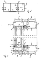
- FIGS. 5 to 9 a second embodiment is shown.
- the same parts are provided with the same reference numerals and are therefore not detailed again here.
- the outer and inner sealing elements 8, 8 ' are here now preferably formed by brushing. However, they can also be the sealing lips described above.
- the inner sealing element 8 ' is now not held in the middle frame part 3 but between insulation body 7 and middle frame part 3. These two elements are designed to form a suitable receptacle, here a groove.
- the insulating body 7 and the middle frame part 3 has a different cross-sectional shape than in the first embodiment.
- the insulation body 7 is hollow in this example.
- On the outer side surfaces of the arms 74 can also be the inner sealing element 8 'attach in a simple manner.
- the inner sealing element 8 ' is held on the insulating body 7, which has a corresponding receiving groove or other fastening means.
- the insulating body 7 can still be covered with a middle frame part 3, in particular made of metal.
- FIG. 6 also recognizable is the carriage 4.
- this survey is also formed by a profile part 13, which is arranged in the web 12 and which has a side wall 13 'as a privacy shield and demarcation with respect to the insulating body 7.
- FIG. 7 is a section through the fixed sash F shown, wherein the inner and outer sealing elements 8, 8 'are not shown.
- the structure corresponds to the section according to AA and is therefore not repeated.
- FIG. 8 shows the section through the sliding window or door T. Again, the structure is identical again.
- FIG. 9 shows the transition region B between fixed and sliding window sash.
- connecting pieces V, V ' which have receiving grooves for the inner and outer sealing elements 8, 8'.
- the inner and outer sealing elements 8, 8 ' are not on the other connecting pieces V, V', but contact the receiving profiles 5.
- the leg L of the connecting piece V, V ' is correspondingly shorter than in the first embodiment. As a result, the insulation is increased, since even here no more cold bridges can arise.
- the frame construction according to the invention has improved thermal insulation and can nevertheless be made relatively narrow. By using as possible Symmetrical items can also minimize manufacturing costs.
Landscapes
- Engineering & Computer Science (AREA)
- Civil Engineering (AREA)
- Structural Engineering (AREA)
- Wing Frames And Configurations (AREA)
- Specific Sealing Or Ventilating Devices For Doors And Windows (AREA)
- Door And Window Frames Mounted To Openings (AREA)
Description
- Die Erfindung betrifft eine Rahmenkonstruktion einer Schiebetür oder eines Schiebefensters gemäss Oberbegriff des Patentanspruchs 1.
- Eine Rahmenkonstruktion ist in
EP-A-0'080'870 offenbart. In einem Hauptrahmen aus Aluminium sind zwei Aufnahmeprofile aus Kunststoff zur Aufnahme von je einem Türflügel angeordnet. Das Aufnahmeprofil des verschiebbaren Türflügels ist mit einem Laufwagen versehen, welcher im Hauptrahmen geführt verschiebbar ist. Die zwei Aufnahmeprofile sind durch ein Trennelement getrennt, welches zwischen die Aufnahmeprofile ragt und welches am Hauptrahmen angeformt ist. Dieses Trennelement dient zudem zur Aufnahme von Dichtungsbürsten, welche gleitend am verschiebbaren Aufnahmeprofil anliegen. - Schiebefenster mit einer ähnlichen Konstruktion offenbart
GB-A-2'150'188 - Beide Konstruktionen weisen den Nachteil auf, dass der Hauptrahmen von aussen nach innen durchgehend gestaltet ist. Somit bildet er eine Kältebrücke zwischen der Aussenund Innenseite des Fensters oder der Türe.
- Auf dem Markt ist ferner eine Konstruktion bekannt, welche zur Vermeidung derartiger Kältebrücken einen zweigeteilten Hauptrahmen aufweist. Dabei sind der innere und der äussere Teil des Rahmens durch einen Isolationskörper voneinander getrennt. Das Aufnahmeprofil des verschiebbaren Türflügels ist innerhalb des äusseren Rahmenteils angeordnet. In diesem äusseren Rahmenteil sind auf beiden Seiten Dichtungsbürsten angeordnet, welche gleitend am verschiebbaren Aufnahmeprofil anliegen.
Die zwei Rahmenteile sind u-förmig gestaltet. Da jedoch ein Schenkel des jeweilig äusseren Teils vom kalten in den warmen Bereich hineinragt, kommt es an dieser Stelle zu Kondenswasserbildung. Ebenso sind die Aufnahmeprofile des Isolierglases nicht isoliert und bilden daher eine durchgehende Kältebrücke. - Des weiteren offenbart
EP-A-1'101'894 eine Rahmenkonstruktion für Schiebetüren, bei welcher jeder Türflügel in einem L-förmigen inneren Rahmen gehalten ist. Die Schenkel des L-förmigen Rahmens erstrecken sich dabei in der unteren horizontalen Richtung und in einer seitlichen vertikalen Richtung. Die zwei freien Seiten des Türflügels laufen in einem äusseren Rahmen, welche in Bereich dieser zwei Seiten einen inneren und einen äusseren Rahmenteil aufweist, welcher durch eine Isolationskörper getrennt ist. Die Fensterscheiben sind entlang dieser zwei Seiten in Aufnahmeprofilen gehalten, welche seitlich mit Bürsten versehen sind. Diese inneren Bürsten gleiten beim Verschieben der Türe entlang des Isolationskörpers. Diese Konstruktion weist den Nachteil auf, dass die freie Fensterfläche durch den L-förmigen inneren Rahmen begrenzt ist. Die Konstruktion eignet sich zudem nur für zweiflüglige Türen und kann für mehrflüglige Türen nicht eingesetzt werden. Zudem weist die Konstruktion im unteren Bereich bedingt durch den unteren Isolationskörper eine relativ hohe Schwelle auf. Da diese Rahmenkonstruktion unterschiedlich aufgebaute Seiten aufweist, ist sie in der Herstellung relativ teuer und aufwendig in der Montage. - Die
BE 1002537 A3
Aus derFR 2 363 686 - Bei der Verwendung von hoch isolierenden Werkstoffen zur Trennung des inneren und des äusseren Rahmens an Schiebetürführungen, die naturgemäss begehbar sind, erweist sich als Nachteil, dass die Isolationsmaterialien nicht sehr abriebfest sind und folglich durch das Begehen abgenützt oder zerquetscht werden. Wird auf die Zwischenisolation, wie in der
FR 2 363 686 - Es ist deshalb Aufgabe der Erfindung, eine Rahmenkonstruktion einer Schiebetür oder eines Schiebefensters zu schaffen, welche die oben genannten Nachteile behebt.
- Diese Aufgabe löst eine Rahmenkonstruktion mit den Merkmalen des Patentanspruchs 1.
- Bei der erfindungsgemässen Rahmenkonstruktion ist der Rahmen dreiteilig ausgebildet, wobei der erste, äussere und der zweite, innere Rahmenteil mindestens entlang der Führung des Laufwagens durch einen Isolationskörper vollständig voneinander getrennt sind. Innere Dichtungselemente liegen dabei gleitend zwischen einem Aufnahmeprofil für einen Türflügel oder Fensterflügel und einem mittleren Rahmenteil an. Im ersten Fall bildet der Isolationskörper den dritten Teil, im zweiten Fall das mittlere Rahmenteil. Die inneren Dichtungselemente sind am mittleren Rahmenteil gehalten.
- Das mittlere Rahmenteil ist vorzugsweise thermisch vollständig vom ersten und vom zweiten Rahmenteil getrennt. Das mittlere Rahmenteil ist zudem von quer zu dessen Längsausdehnung von einem weiteren Dichtungsteil, vorzugsweise einer Bürste, unterbrochen.
- Durch die Anordnung der inneren Dichtelemente bzw. den weiteren Dichtungsteil wird verhindert, dass Kältebrücken zwischen dem inneren und dem äusseren Rahmenteil entstehen. Zudem wird die Bildung von Kondenswasser vermieden.
- Die Rahmenkonstruktion lässt sich im unteren Bereich schwellenlos ausbilden. Der frei Fensterbereich ist maximiert. Da sich auf allen vier Seiten der Rahmenkonstruktion die identischen Teile für die inneren, äusseren und mittleren Rahmenteile sowie für den Isolationskörper verwenden lassen, sind die Herstellung- und Montagekosten minimiert.
- Weitere vorteilhafte Ausführungsformen gehen aus den abhängigen Patentansprüchen hervor.
- Im folgenden wird der Erfindungsgegenstand anhand von bevorzugten Ausführungsbeispielen, welche in den beiliegenden Zeichnungen dargestellt sind, erläutert. Es zeigen:
- Figur 1
- eine Ansicht einer Schiebetüre mit der erfindungsgemässen Rahmenkonstruktion gemäss einer ersten Ausführungsform;
- Figur 2
- einen Schnitt entlang der Linie B-B gemäss
Figur 1 ; - Figur 3
- einen Schnitt entlang der Linie A-A gemäss
Figur 1 ; - Figur 4
- einen Schnitt entlang der Linie C-C gemäss
Fig. 1 ; - Figur 5
- eine Ansicht einer Schiebetüre mit der erfindungsgemässen Rahmenkonstruktion gemäss einer zweiten Ausführungsform;
- Figur 6
- einen Schnitt entlang der Linie B-B gemäss
Figur 5 ; - Figur 7
- einen Schnitt entlang der Linie A-A gemäss
Figur 5 ; - Figur 8
- einen Schnitt entlang der Linie C-C gemäss
Figur 5 und - Figur 9
- einen Schnitt entlang der Linie D-D gemäss
Figur 5 . -
Figur 1 zeigt eine Schiebetüre S mit einer Rahmenkonstruktion R, in welchem ein fester Türflügel F und ein verschiebbarer Türflügel T angeordnet sind gemäss einer ersten Ausführungsform. Es ist auch möglich, beide Türflügel verschiebbar anzuordnen und/oder mehr als zwei Türflügel in die Schiebetüre einzusetzen. - Die erfindungsgemässe Rahmenkonstruktion R ist in den
Figuren 2 und3 besser ersichtlich. Der Hauptrahmen ist in einen ersten Rahmenteil 1 und einen zweiten Rahmenteil 2 unterteilt. Der erste Rahmenteil 1 ist hier aussen, der zweite Rahmenteil 2 innen angeordnet. Die Anordnung kann aber auch umgekehrt sein. Der äussere und der innere Rahmenteil 1,2 sind durch je vier Profilelemente gebildet, welche je eine Längsseite der Rahmenkonstruktion bilden. Die einzelnen Profilelemente eines Rahmenteils 1,2 sind bis auf ihre Länge identisch ausgebildet. InFigur 2 sind die unteren und oberen Profilelemente sichtbar, inFigur 3 die rechten und linken. Im folgenden wird von Rahmenteil 1, 2 gesprochen, wobei jeweils ein entsprechendes Profilelement gemeint ist. - Im folgenden wird die Rahmenkonstruktion anhand der
Figur 2 beschrieben. Der erste Rahmenteil 1 bzw. das entsprechende Profilelement weist einen im wesentlichen u-förmigen Querschnitt auf. Dabei ist ein äusserer Schenkel 10 des Rahmenteils 1 länger ausgebildet als ein innerer Schenkel 11. Die zwei Schenkel sind über einen Steg 12 miteinander verbunden. - Der innere Rahmenteil 2 bzw. das entsprechende Profilelement ist vorzugsweise identisch aufgebaut wie der äussere Rahmenteil 1. Dadurch lassen sich die Herstellungskosten minimieren. Er ist spiegelsymmetrisch zum ersten Rahmenteil 1 angeordnet, so dass sein langer Schenkel 20 nach innen und sein kurzer Schenkel 21 nach aussen gerichtet ist.
- Zwischen den zwei Rahmenteilen 1, 2 ist ein Isolationskörper 7 zur Verhinderung von Kältebrücken angeordnet. Er befindet sich neben einer durch die Fernster- oder Türfläche definierten Ebene. Dieser Isolationskörper 7 erstreckt sich auf allen vier Seiten über die gesamte Länge der Rahmenkonstruktion. Er ist ein Profilelement, welches vorzugsweise aus einem wärmeisolierenden Kunststoff,, aus Schaumstoff oder einem anderen geeigneten Isolationsmaterial gefertigt ist. Auch er ist vorzugsweise spiegelsymmetrisch ausgebildet.
- An seinem von der Türfläche entfernten Ende weist er einen Kopf 70 auf, welcher sich zur Mitte des Isolationskörpers hin zu einem Hals 71 verjüngt. Dieses Ende befindet sich je nach Seite der Rahmenkonstruktion oben, unten, rechts oder links. Die kurzen Schenkel 11, 21 des inneren und äusseren Rahmenteils 1, 2 weisen eine hierzu passende Form auf, so dass sie formschlüssig am Isolationskörper 7 gehalten sind. Der Formschluss erhöht die Stabilität. Dabei erstrecken sich diese kurzen Schenkel 11, 21 vorzugsweise maximal bis zur mittleren Höhe des Isolationskörpers 7.
- An dem der Türfläche zugewandten Ende des Isolationskörpers 7 ist ein mittleres Rahmenteil 3 des Hauptrahmens aufgesteckt. Auch dieses ist vorzugsweise symmetrisch ausgebildet. Es weist ebenfalls einen im wesentlichen u-förmigen Querschnitt auf, wobei sein Steg auf beiden Seiten verlängert ist und nach aussen vorsteht und die Schenkel gleich lang ausgebildet sind, wobei sie L-förmig nach aussen gebogen sind. Die Schenkel sind dabei so kurz ausgebildet, dass das mittlere Rahmenteil 3 mindestens vollständig vom inneren und äusseren Rahmenteil 1, 2 getrennt ist.
- Das Türblatt des festen wie auch des verschiebbaren Türflügels F, T ist in einem Aufnahmeprofil 5 angeordnet. Dieses Aufnahmeprofil 5 besteht wiederum aus vier sich entlang der Seiten der Rahmenkonstruktion erstreckenden Einzelprofile, welche auf bekannte Weise miteinander verbunden sind. Üblicherweise werden sie einfach an die Glasscheibe des jeweiligen Türflügels geklebt. In
Figur 2 ist das obere und untere Aufnahmeprofil 5 dargestellt, in derFigur 3 das linke und rechte jedes Türflügels F, T. Im folgenden wird wiederum zuerst aufFigur 2 eingegangen. - Das Aufnahmeprofil 5 weist einen u-förmigen, vorzugsweise symmetrischen Querschnitt auf. Im hier dargestellten Beispiel weist jeder Türflügel F, T eine Doppelverglasung auf, so dass in jedem Aufnahmeprofil 5 eine äussere Glasscheibe 6 und eine innere Glasscheibe 6' fixiert sind, welche durch einen Glasrandverbund 60 im Abstand zueinander gehalten sind.
- Das Aufnahmeprofil 5 weist einen Steg auf, welcher vorzugsweise durch ein wärmeisolierendes Einsatzelement 50 durchsetzt ist. So ist auch hier wiederum eine Kältebrücke von aussen nach innen isolierend unterbrochen.
- Der Rahmenteil des festen Türflügels F, hier der innere Rahmenteil 2, ist in seinem dem Türflügel vorstehenden Bereich mit einem Abdeckprofil 9, insbesondere aus Aluminium, zugedeckt. Dadurch wird verhindert, dass Schmutz in das nach oben offene Profil des Rahmenteils 2 gelangt. Sollen beide Türflügel verschiebbar ausgestaltet sein, so erübrigt sich das Abdeckprofil 9.
- Das untere Aufnahmeprofil 5 des verschiebbaren Türflügels T ist auf einem Laufwagen 4 angeordnet. Dieser Laufwagen 4 weist mindestens ein Laufrad 41 auf, welches auf einer Erhebung des unteren Stegs 12 des äusseren Rahmenteils 1 geführt gelagert ist. Ferner ist es durch seitlich des Laufrads 41 angeordnete Kugellager 42 geführt.
- Zwischen dem verschiebbaren Aufnahmeprofil 5 und der lagefixierten Rahmenkonstruktion liegen Dichtungselemente 8, 8' gleitend an. Diese Dichtungselemente 8, 8' erstrecken sich vorzugsweise über die gesamte Länge des Aufnahmeprofils 5 und somit der Türfläche. Im hier dargestellten Beispiel sind die Dichtungselemente 8, 8' Dichtungslippen, welche gleitend am Aufnahmeprofil 5 anliegen und mit einem verdickten Kopf in entsprechenden Aufnahmen der Rahmenkonstruktion gehalten sind. Es ist jedoch auch möglich, Bürsten oder anders geformte Dichtungselemente einzusetzen.
- Die Dichtungslippen haben den Vorteil, dass sie weniger Schmutz auffangen als die Bürsten. In einer bevorzugten Ausführungsform sind sie aus einem geeigneten Kunststoff oder Gummi gefertigt und weisen einen integrierten Draht auf. Dieser Draht verstärkt die Dichtlippen und verhindert, dass sie vom verschiebbaren Türflügel mitgerissen werden. Die Dichtung ist somit auch nach längerem Gebrauch der Schiebetüre noch gewährleistet. Diese Dichtungselemente mit integriertem Draht lassen sich auch in anderen Rahmenkonstruktionen von Schiebetüren oder Schiebefenstern einsetzen.
- Wie in
Figur 2 dargestellt, ist der verdickte Kopf des äusseren Dichtungselements 8 in einer durch den äusseren Schenkel 10 des äusseren Rahmenteils 1 gebildete Aufnahmenut gehalten. Das innere Dichtungselement 8' hingegen ist mit seinem verdickten Kopf in einer Aufnahmenut des mittleren Rahmenteils 3 gehalten, welche durch den L-förmig gebogenen Schenkel und den vorstehenden Steg gebildet ist. Beim inneren Rahmenteil 2 ist es genau umgekehrt. Werden Bürsten verwendet, so sind diese vorzugsweise ebenfalls in der Rahmenkonstruktion gehalten. - Am oberen Aufnahmeprofile 5 des verschiebbaren Türflügels T liegen ebenfalls derartige Dichtungselemente 8, 8' gleitend an. Auch diese sind wiederum in den oben beschriebenen Teilen der Rahmenkonstruktion gehalten.
- Wie in
Figur 3 ersichtlich ist, ist das Aufnahmeprofil 5 des verschiebbaren Türflügels T auf einer Seite in einer Griffeinheit 5' gehalten, an welcher auf einer, hier auf beiden Seiten ein Betätigungsgriff G angeordnet ist. Die Griffeinheit 5' besteht aus zwei Profilelementen 51 und mindestens einem, hier zwei diese verbindenden Isolationsstege 52. Hier liegen nun die Dichtungselemente 8, 8' nicht an den Aufnahmeprofilen 5, sondern an der Griffeinheit 5' dichtend an. - In
Figur 3 sind der feste Fensterflügel F sowie der Übergangsbereich B vom festen zum verschiebbaren Fensterflügel F, T sichtbar. Der feste Fensterflügel F ist ebenfalls auf allen vier Seiten in einem Aufnahmeprofil gehalten, welches mit Dichtungselementen, vorzugsweise mit den oben beschriebenen Dichtlippen 8, 8' gegenüber der Rahmenkonstruktion gedichtet ist. - Der Übergangsbereich B besteht aus zwei symmetrisch ausgebildeten, identisch geformten Verbindungsstücken V, V' in Form von Profilelementen. Jedes Verbindungsstück V bildet eine feste Aufnahme für das Aufnahmeprofil 5 des festen beziehungsweise des verschiebbaren Türflügels F, T. Es weist zudem eine zum anderen Türflügel hin gerichtete V-förmige Nut auf, dessen äusserer Schenkel eine nach aussen zum anderen Türflügel hin gerichtete Aufnahmenut für das Dichtungselement 8, 8' bildet. Die äusseren Schenkel der jeweiligen V-förmigen Nut ragen in die V-förmige Nut des anderen Verbindungsstücks V, V' hinein. Die konische Ausbildung ermöglicht einen genügenden Anpressdruck. Die Dichtungselemente 8, 8' liegen an den inneren Schenkeln der V-förmigen Nuten an. Dadurch ist durch die Dichtungslippe und den labyrinth-artigen Übergangsbereich eine optimale Wärmeisolation gewährleistet.
- In
Figur 4 ist erkennbar, dass das mittlere Rahmenteil 3 nicht durchgehend ausgebildet ist, sondern von einem weiteren Dichtungsteil 30 unterbrochen ist. Dieses Dichtungsteil 30 ist vorzugsweise eine Dichtungsbürste, dessen Borsten zur Fläche des Türflügels hin gerichtet sind. Der Unterbruch befindet sich dabei zwischen dem festen und dem verschiebbaren Türflügel T, F, wenn sich diese in ihrer geschlossenen Position befinden. Dadurch wird gewährleistet, dass keine Teile vom kalten in den warmen Bereich ragen und somit keine Kältebrücken entstehen. - In den
Figuren 5 bis 9 ist eine zweite Ausführungsform dargestellt. Gleiche Teile sind mit gleichen Bezugszeichen versehen und werden hier deshalb nicht nochmals detailliert aufgeführt. - Die äusseren und inneren Dichtelemente 8, 8' sind hier nun vorzugsweise durch Bürsten gebildet. Sie können jedoch auch die oben beschriebenen Dichtlippen sein. Das innere Dichtelement 8' ist nun nicht im mittleren Rahmenteil 3 sondern zwischen Isolationskörper 7 und mittlerem Rahmenteil 3 gehalten. Diese zwei Elemente sind entsprechend ausgebildet, um eine geeignete Aufnahme, hier eine Nut, zu bilden.
- Wie in
Figur 6 erkennbar ist, weist der Isolationskörper 7 und der mittlere Rahmenteil 3 eine andere Querschnittsform auf als im ersten Ausführungsbeispiel. Insbesondere ist in diesem Beispiel der Isolationskörper 7 hohl ausgebildet. Zudem weist der Isolationskörper Arme 72 und der mittlere Rahmenteil 3 Füsse 31 auf, welche eine formschlüssige Verbindung dieser zwei Teile gewährleisten. An den äusseren Seitenflächen der Arme 74 lässt sich zudem das innere Dichtelement 8' auf einfache Weise befestigen. - In einer weiteren hier nicht dargestellten Variante ist das innere Dichtelement 8' am Isolationskörper 7 gehalten, welcher eine entsprechende Aufnahmenut oder andere Befestigungsmittel aufweist. Der Isolationskörper 7 kann jedoch nach wie vor mit einem mittleren Rahmenteil 3, insbesondere aus Metall abgedeckt sein.
- In
Figur 6 ebenfalls erkennbar ist der Laufwagen 4. Im Gegensatz zur Ausführungsform gemässFigur 2 ist er nun nicht auf einer Erhebung des Stegs 12 mit rundem Querschnitt gelagert sondern auf einer Erhebung mit dreieckförmigen Querschnitt. Vorzugsweise wird diese Erhebung zudem durch ein Profilteil 13 gebildet, welches im Steg 12 angeordnet ist und welches eine seitliche Wand 13' als Sichtschutz und Abgrenzung gegenüber dem Isolationskörper 7 aufweist. - In
Figur 7 ist ein Schnitt durch den festen Fensterflügel F dargestellt, wobei die inneren und äusseren Dichtelemente 8, 8' nicht eingezeichnet sind. Der Aufbau entspricht dem Schnitt gemäss A-A und wird deshalb nicht wiederholt. -
Figur 8 zeigt den Schnitt durch den verschiebbaren Fenster oder Türflügel T. Auch hier ist der Aufbau wieder identisch. -
Figur 9 zeigt den Übergangsbereich B zwischen festem und verschiebbaren Fensterflügel. Es sind wiederum Verbindungsstücke V, V' vorhanden, welche Aufnahmenuten für die inneren und äusseren Dichtelemente 8, 8' aufweisen. Im Gegensatz zu ersten Ausführungsform liegen die inneren und äusseren Dichtelemente 8, 8' jedoch nicht an den anderen Verbindungsstücken V, V' an, sondern kontaktieren die Aufnahmeprofile 5. Der Schenkel L des Verbindungsstücks V, V' ist entsprechend kürzer ausgebildet als in der ersten Ausführungsform. Dadurch wird die Isolation noch erhöht, da auch hier keine Kältebrücken mehr entstehen können. - Die erfindungsgemässe Rahmenkonstruktion weist eine verbesserte Wärmeisolation auf und lässt sich trotzdem relativ schmal ausgestalten. Durch die Verwendung von möglichst symmetrischen Einzelteilen lassen sich zudem die Herstellungskosten minimieren.
-
- S
- Schiebetür
- R
- Rahmen
- T
- verschiebbarer Türflügel
- F
- fester Türflügel
- G
- Betätigungsgriff
- B
- Übergangsbereich
- V
- Verbindungsstück
- V'
- Verbindungsstück
- L
- Schenkel
- 1
- äusserer Rahmenteil
- 10
- äusserer Schenkel
- 11
- innerer Schenkel
- 12
- Steg
- 13
- Profilteil
- 13'
- Wand
- 2
- innerer Rahmenteil
- 20
- langer Schenkel
- 21
- kurzer Schenkel
- 3
- mittlerer Rahmenteil
- 30
- Dichtungsteil
- 31
- Fuss
- 4
- Laufwagen
- 41
- Laufrad
- 42
- Kugellager
- 5
- Aufnahmeprofil
- 50
- Einsatzelement
- 51
- Profilelement
- 52
- Isolationssteg
- 5'
- Griffeinheit
- 6
- äussere Glasscheibe
- 6'
- innere Glasscheibe
- 60
- Glasrandverbund
- 7
- Isolationskörper
- 70
- Kopf
- 71
- Hals
- 72
- Arm
- 8
- äusseres Dichtelement
- 8'
- inneres Dichtelement
- 9
- Abdeckprofil
Claims (9)
- Rahmenkonstruktion einer Schiebetür oder eines Schiebefensters miteinem Hauptrahmen,einem Laufwagen (4) zur Aufnahme eines verschiebbaren Türflügels (T) oder Fensterflügels,wobei der Laufwagen (4) im Hauptrahmen geführt verschiebbar angeordnet ist,Aufnahmeprofile (5) zur Aufnahme der Türflügel (F,T) oder Fensterflügel,äussere Dichtungselemente (8), weiche gleitend zwischen den Aufnahmeprofilen (5) und einem äusseren Bereich des Hauptrahmens anliegen und innere Dichtungselemente (8'), welche gleitend zwischen den Aufnahmeprofilen (5) und einem inneren Bereich des Hauptrahmens anliegen,und einen Isolationskörper (7),wobei der Hauptrahmen einen äusseren und einen inneren Rahmenteil (1,2) aufweist, und wobei
der äussere und der innere Rahmenteil (1,2) mindestens entlang der Führung des Laufwagens (4) durch den Isolationskörper (7) vollständig voneinander getrennt sind,
das innere Dichtungselement (8') am Isolationskörper (7) oder an einem mittleren vom inneren und äusseren Rahmenteil (1,2) getrennten Rahmenteil (3) des Hauptrahmens anliegt,
dadurch gekennzeichnet, dass
mindestens das am unteren horizontal verlaufenden Rahmenabschnitt auf den Isolationskörper (7) aufgesetzte mittlere Rahmenteil (3) aus Metall besteht und nicht durchgehend ausgebildet ist. - Rahmenkonstruktion nach Anspruch 1, dadurch gekennzeichnet, dass das Rahmenteil (3) von einem Dichtungsteil (30) unterbrochen ist.
- Rahmenkonstruktion nach einem der Ansprüche 1 oder 2, dadurch gekennzeichnet, dass das mittlere Rahmenteil (3) formschlüssig auf dem Isolationskörper (7) aufgesteckt ist.
- Rahmenkonstruktion nach Anspruch 2, dadurch gekennzeichnet, dass der Dichtungsteil (30) eine Dichtungsbürste ist, deren Borsten zur Fläche des Türflügels hin gerichtet sind.
- Rahmenkonstruktion nach einem der Ansprüche 1 bis 4, dadurch gekennzeichnet, dass das innere und äussere Rahmenteil (1,2) an allen vier Seiten des Hauptrahmens durch den Isolationskörper (7) vollständig voneinander getrennt sind, und dass an jeder Seite des Hauptrahmens innere Dichtungselemente (8') vorhanden sind, welche an einem mittleren vom inneren und äusseren Rahmenteil (1,2) getrennten Rahmenteil (3) des Hauptrahmens anliegen und dass die vier Seiten des Hauptrahmens identisch ausgebildete Rahmenteile und Isolationskörper und gegebenenfalls mittlere Rahmenteile aufweisen.
- Rahmenkonstruktion nach einem der Ansprüche 1 bis 5, dadurch gekennzeichnet, dass das innere Dichtungsteil (8') in einer Aufnahme des mittleren Rahmenteils (3) der Rahmenkonstruktion gehalten ist, welche durch einen L-förmig gebogenen Schenkel und einen vorstehenden Steg gebildet ist.
- Rahmenkonstruktion nach einem der Ansprüche 1 bis 6, dadurch gekennzeichnet, dass das Aufnahmeprofil (5) einen Steg aufweist, welcher durch ein wärmeisolierendes Einsatzelement (50) durchsetzt ist, welches eine Kältebrücke von aussen nach innen isolierend unterbricht.
- Rahmenkonstruktion nach einem der Ansprüche 1 bis 7, dadurch gekennzeichnet, dass der Laufwagen (4) mindestens ein Laufrad (41) mit einer beidseitigen seitlichen Kugellagerführung (42) aufweist.
- Rahmenkonstruktion nach einem der Ansprüche 1 bis 8, dadurch gekennzeichnet, dass äussere Dichtungselemente (8) in einem äusseren Schenkel eines Rahmenteils (12) gehalten sind und gleitend an den Aufnahmeprofilen (5) anliegen und dass innere Dichtungselemente (8') im Isolationskörper (7) oder im mittleren Rahmenteil (3) oder zwischen Isolationskörper (7) und mittlerem Rahmenteil (3) gehalten sind und gleitend an den Aufnahemprofilen (5) anliegen.
Applications Claiming Priority (2)
| Application Number | Priority Date | Filing Date | Title |
|---|---|---|---|
| CH6052002 | 2002-04-10 | ||
| CH6052002 | 2002-04-10 |
Publications (3)
| Publication Number | Publication Date |
|---|---|
| EP1353034A2 EP1353034A2 (de) | 2003-10-15 |
| EP1353034A3 EP1353034A3 (de) | 2004-09-15 |
| EP1353034B1 true EP1353034B1 (de) | 2008-07-30 |
Family
ID=28048301
Family Applications (1)
| Application Number | Title | Priority Date | Filing Date |
|---|---|---|---|
| EP03405238A Expired - Lifetime EP1353034B1 (de) | 2002-04-10 | 2003-04-08 | Rahmenkonstruktion einer Schiebetür |
Country Status (6)
| Country | Link |
|---|---|
| EP (1) | EP1353034B1 (de) |
| AT (1) | ATE403057T1 (de) |
| DE (1) | DE50310220D1 (de) |
| DK (1) | DK1353034T3 (de) |
| ES (1) | ES2311684T3 (de) |
| PT (1) | PT1353034E (de) |
Cited By (5)
| Publication number | Priority date | Publication date | Assignee | Title |
|---|---|---|---|---|
| US8286396B2 (en) | 2006-12-22 | 2012-10-16 | Technoform Bautec Holding Gmbh | Plastic profile for window, door and facade elements |
| EP2400099B1 (de) | 2010-06-25 | 2016-07-13 | DORMA Deutschland GmbH | Thermisch isolierende Flügelanlage |
| EP3865644A1 (de) | 2020-02-17 | 2021-08-18 | Seu Plastics One Man L.L.C. | Verriegelungsmechanismus für versteckten einbaurahmen |
| DE102010023607C5 (de) | 2010-06-14 | 2022-06-23 | Landert Group Ag | Thermisch isoliertes Profil für Schiebetüren |
| MA61741A1 (fr) * | 2023-08-08 | 2025-02-28 | Bahrain Aluminium Extrusion Co. (Balexco) B.S.C. Closed | Systèmes Balexco - Primo |
Families Citing this family (14)
| Publication number | Priority date | Publication date | Assignee | Title |
|---|---|---|---|---|
| FR2861794B1 (fr) * | 2003-10-30 | 2006-02-03 | Daniel Vinatier | Menuiserie pour vantaux coulissants comportant un masque de protection thermique de l'encadrement du vitrage. |
| DE10353822A1 (de) * | 2003-11-18 | 2005-06-23 | Eduard Hueck Gmbh & Co Kg | Schwellenprofil für eine Schiebetür oder ein Schiebefenster |
| US7520093B2 (en) | 2004-01-13 | 2009-04-21 | Beat Guhl | Frame construction of a sliding door |
| FR2912175B1 (fr) * | 2007-02-02 | 2009-04-17 | Norsk Hydro As | Chassis de porte ou fenetre a serrure comportant un cadre et au moins un ouvrant coulissant. |
| ITBO20070243A1 (it) | 2007-04-03 | 2008-10-04 | Gsg Int Spa | Accessorio per profilati per serramenti scorrevoli. |
| EP2281990A1 (de) | 2009-06-29 | 2011-02-09 | Orchidées Constructions S.A. | Schiebeglasfenster oder -tür |
| IT1394972B1 (it) * | 2009-07-31 | 2012-08-07 | Gsg Int Spa | Infisso scorrevole rinforzato. |
| CN101886510B (zh) * | 2010-07-19 | 2011-09-07 | 浙江瑞明节能门窗股份有限公司 | 一种铝合金推拉节能门窗系统 |
| AT511726B1 (de) | 2011-07-15 | 2013-05-15 | Alfons Oberhofer | Vorrichtung zum verschieben eines schiebeelements |
| FR2981976B1 (fr) * | 2011-11-02 | 2015-01-02 | Norsk Hydro As | Fermeture coulissante de baie de construction |
| CN104005664A (zh) * | 2014-05-12 | 2014-08-27 | 安徽同曦金鹏铝业有限公司 | 隔热推拉门封边盖板型材 |
| EP3034767B1 (de) | 2014-12-18 | 2017-11-01 | dormakaba Deutschland GmbH | Schiebewandsystem |
| WO2017191048A1 (en) | 2016-05-03 | 2017-11-09 | Technoform Bautec Holding Gmbh | Sash for a sliding window or a sliding door and method for providing an untreated metal surface in such a sash |
| FR3095001B1 (fr) * | 2019-04-11 | 2021-04-30 | Titime | Chassis pour fenetre coulissante |
Family Cites Families (5)
| Publication number | Priority date | Publication date | Assignee | Title |
|---|---|---|---|---|
| FR2363686A2 (fr) * | 1976-08-31 | 1978-03-31 | Fey Adam | Fenetre ou porte coulissante |
| EP0080870A1 (de) | 1981-11-27 | 1983-06-08 | L.B. (Plastics) Limited | Terrassentürkonstruktionen |
| GB8330937D0 (en) | 1983-11-19 | 1983-12-29 | Lb Plastics Ltd | Sliding window construction |
| BE1002537A3 (fr) * | 1988-10-07 | 1991-03-19 | Catulle Ludovic | Profiles en aluminium a rupture de pont thermique pour dormants de fenetres et de portes-fenetres coulissantes. |
| FR2801337B1 (fr) | 1999-11-22 | 2002-01-18 | Technal | Nouveau chassis de porte ou fenetre coulissante |
-
2003
- 2003-04-08 DK DK03405238T patent/DK1353034T3/da active
- 2003-04-08 PT PT03405238T patent/PT1353034E/pt unknown
- 2003-04-08 DE DE50310220T patent/DE50310220D1/de not_active Expired - Lifetime
- 2003-04-08 ES ES03405238T patent/ES2311684T3/es not_active Expired - Lifetime
- 2003-04-08 EP EP03405238A patent/EP1353034B1/de not_active Expired - Lifetime
- 2003-04-08 AT AT03405238T patent/ATE403057T1/de active
Cited By (5)
| Publication number | Priority date | Publication date | Assignee | Title |
|---|---|---|---|---|
| US8286396B2 (en) | 2006-12-22 | 2012-10-16 | Technoform Bautec Holding Gmbh | Plastic profile for window, door and facade elements |
| DE102010023607C5 (de) | 2010-06-14 | 2022-06-23 | Landert Group Ag | Thermisch isoliertes Profil für Schiebetüren |
| EP2400099B1 (de) | 2010-06-25 | 2016-07-13 | DORMA Deutschland GmbH | Thermisch isolierende Flügelanlage |
| EP3865644A1 (de) | 2020-02-17 | 2021-08-18 | Seu Plastics One Man L.L.C. | Verriegelungsmechanismus für versteckten einbaurahmen |
| MA61741A1 (fr) * | 2023-08-08 | 2025-02-28 | Bahrain Aluminium Extrusion Co. (Balexco) B.S.C. Closed | Systèmes Balexco - Primo |
Also Published As
| Publication number | Publication date |
|---|---|
| ATE403057T1 (de) | 2008-08-15 |
| DE50310220D1 (de) | 2008-09-11 |
| PT1353034E (pt) | 2008-10-30 |
| EP1353034A2 (de) | 2003-10-15 |
| ES2311684T3 (es) | 2009-02-16 |
| EP1353034A3 (de) | 2004-09-15 |
| DK1353034T3 (da) | 2008-11-24 |
Similar Documents
| Publication | Publication Date | Title |
|---|---|---|
| EP1353034B1 (de) | Rahmenkonstruktion einer Schiebetür | |
| EP0009652B1 (de) | Bausatz für vertikale oder horizontale Schiebefenster | |
| DE202008013043U1 (de) | Hebe-Schiebe-Fenster oder -Tür sowie Abdichtelement | |
| DE2920445A1 (de) | Verschlussanordnung mit verglasung | |
| EP1108849B1 (de) | Torblatt eines Sektionaltores | |
| EP1057961B1 (de) | Schwellenprofil für Gebäudetüren sowie Gebäudetür | |
| DE8206788U1 (de) | Lueftungsvorrichtung fuer den einbau in fenster und/oder in andere wandoeffnungen von gebaeuden | |
| DE19641956A1 (de) | Vorrichtung zum Abdichten des Spaltes unter einer Tür | |
| DE19505222C2 (de) | Flügelanordnung, im wesentlichen bestehend aus einem Stockrahmen und zwei an diesem Stockrahmen schwenkbar vorgesehenen Flügelrahmen | |
| DE20003060U1 (de) | Flügelprofil | |
| AT413293B (de) | Schiebeelement-dichtung | |
| EP0784144A1 (de) | Magnetische Türdichtung und Zusatzprofile zu deren Herstellung | |
| EP0418629A1 (de) | Paneele für ein Sektionaltor | |
| AT399198B (de) | Falt- oder schwingflügeltür | |
| EP2610420A2 (de) | Hebe/Schiebetür | |
| DE2342607A1 (de) | Mit mehrfachverglasung versehenes fenster oder versehene tuere mit aus kunststoff bestehendem fluegelrahmen | |
| EP0016957A1 (de) | Bodenschwelle mit Laufschiene | |
| DE102018112434A1 (de) | Fenster | |
| CH637728A5 (de) | Waermegedaemmtes schwing- oder wendefluegelfenster. | |
| EP1555368A1 (de) | Beschlag für eine Ausstell- und Kippbewegung eines Flügels eines Gebäudefensters oder einer Gebäudetür sowie Parallelschiebekipp-Fenster oder -Tür mit einem solchen Beschlag | |
| DE19609624C2 (de) | Gebäudefenster und/oder Gebäudefenstertür | |
| DE29718784U1 (de) | Lamellenfenster | |
| AT389734B (de) | Stalltuer | |
| DE3015822A1 (de) | Fenster, dessen rahmen metall- und kunststoffprofilteile aufweisen | |
| DE19622725C2 (de) | Gebäudefenster und/oder Gebäudefenstertür |
Legal Events
| Date | Code | Title | Description |
|---|---|---|---|
| PUAI | Public reference made under article 153(3) epc to a published international application that has entered the european phase |
Free format text: ORIGINAL CODE: 0009012 |
|
| AK | Designated contracting states |
Kind code of ref document: A2 Designated state(s): AT BE BG CH CY CZ DE DK EE ES FI FR GB GR HU IE IT LI LU MC NL PT RO SE SI SK TR |
|
| AX | Request for extension of the european patent |
Extension state: AL LT LV MK |
|
| PUAL | Search report despatched |
Free format text: ORIGINAL CODE: 0009013 |
|
| AK | Designated contracting states |
Kind code of ref document: A3 Designated state(s): AT BE BG CH CY CZ DE DK EE ES FI FR GB GR HU IE IT LI LU MC NL PT RO SE SI SK TR |
|
| AX | Request for extension of the european patent |
Extension state: AL LT LV MK |
|
| 17P | Request for examination filed |
Effective date: 20041216 |
|
| AKX | Designation fees paid |
Designated state(s): AT BE BG CH CY CZ DE DK EE ES FI FR GB GR HU IE IT LI LU MC NL PT RO SE SI SK TR |
|
| 17Q | First examination report despatched |
Effective date: 20070220 |
|
| 17Q | First examination report despatched |
Effective date: 20070220 |
|
| GRAP | Despatch of communication of intention to grant a patent |
Free format text: ORIGINAL CODE: EPIDOSNIGR1 |
|
| GRAS | Grant fee paid |
Free format text: ORIGINAL CODE: EPIDOSNIGR3 |
|
| GRAA | (expected) grant |
Free format text: ORIGINAL CODE: 0009210 |
|
| AK | Designated contracting states |
Kind code of ref document: B1 Designated state(s): AT BE BG CH CY CZ DE DK EE ES FI FR GB GR HU IE IT LI LU MC NL PT RO SE SI SK TR |
|
| REG | Reference to a national code |
Ref country code: GB Ref legal event code: FG4D Free format text: NOT ENGLISH |
|
| REG | Reference to a national code |
Ref country code: CH Ref legal event code: EP |
|
| REF | Corresponds to: |
Ref document number: 50310220 Country of ref document: DE Date of ref document: 20080911 Kind code of ref document: P |
|
| REG | Reference to a national code |
Ref country code: IE Ref legal event code: FG4D Free format text: LANGUAGE OF EP DOCUMENT: GERMAN |
|
| REG | Reference to a national code |
Ref country code: PT Ref legal event code: SC4A Free format text: AVAILABILITY OF NATIONAL TRANSLATION Effective date: 20081020 |
|
| REG | Reference to a national code |
Ref country code: DK Ref legal event code: T3 |
|
| REG | Reference to a national code |
Ref country code: SE Ref legal event code: TRGR |
|
| REG | Reference to a national code |
Ref country code: ES Ref legal event code: FG2A Ref document number: 2311684 Country of ref document: ES Kind code of ref document: T3 |
|
| PG25 | Lapsed in a contracting state [announced via postgrant information from national office to epo] |
Ref country code: FI Free format text: LAPSE BECAUSE OF FAILURE TO SUBMIT A TRANSLATION OF THE DESCRIPTION OR TO PAY THE FEE WITHIN THE PRESCRIBED TIME-LIMIT Effective date: 20080730 Ref country code: SI Free format text: LAPSE BECAUSE OF FAILURE TO SUBMIT A TRANSLATION OF THE DESCRIPTION OR TO PAY THE FEE WITHIN THE PRESCRIBED TIME-LIMIT Effective date: 20080730 Ref country code: BG Free format text: LAPSE BECAUSE OF FAILURE TO SUBMIT A TRANSLATION OF THE DESCRIPTION OR TO PAY THE FEE WITHIN THE PRESCRIBED TIME-LIMIT Effective date: 20081030 |
|
| REG | Reference to a national code |
Ref country code: IE Ref legal event code: FD4D |
|
| PG25 | Lapsed in a contracting state [announced via postgrant information from national office to epo] |
Ref country code: IE Free format text: LAPSE BECAUSE OF FAILURE TO SUBMIT A TRANSLATION OF THE DESCRIPTION OR TO PAY THE FEE WITHIN THE PRESCRIBED TIME-LIMIT Effective date: 20080730 Ref country code: EE Free format text: LAPSE BECAUSE OF FAILURE TO SUBMIT A TRANSLATION OF THE DESCRIPTION OR TO PAY THE FEE WITHIN THE PRESCRIBED TIME-LIMIT Effective date: 20080730 |
|
| PG25 | Lapsed in a contracting state [announced via postgrant information from national office to epo] |
Ref country code: RO Free format text: LAPSE BECAUSE OF FAILURE TO SUBMIT A TRANSLATION OF THE DESCRIPTION OR TO PAY THE FEE WITHIN THE PRESCRIBED TIME-LIMIT Effective date: 20080730 Ref country code: SK Free format text: LAPSE BECAUSE OF FAILURE TO SUBMIT A TRANSLATION OF THE DESCRIPTION OR TO PAY THE FEE WITHIN THE PRESCRIBED TIME-LIMIT Effective date: 20080730 Ref country code: CZ Free format text: LAPSE BECAUSE OF FAILURE TO SUBMIT A TRANSLATION OF THE DESCRIPTION OR TO PAY THE FEE WITHIN THE PRESCRIBED TIME-LIMIT Effective date: 20080730 |
|
| PLBE | No opposition filed within time limit |
Free format text: ORIGINAL CODE: 0009261 |
|
| STAA | Information on the status of an ep patent application or granted ep patent |
Free format text: STATUS: NO OPPOSITION FILED WITHIN TIME LIMIT |
|
| 26N | No opposition filed |
Effective date: 20090506 |
|
| PG25 | Lapsed in a contracting state [announced via postgrant information from national office to epo] |
Ref country code: MC Free format text: LAPSE BECAUSE OF NON-PAYMENT OF DUE FEES Effective date: 20090430 |
|
| PG25 | Lapsed in a contracting state [announced via postgrant information from national office to epo] |
Ref country code: GR Free format text: LAPSE BECAUSE OF FAILURE TO SUBMIT A TRANSLATION OF THE DESCRIPTION OR TO PAY THE FEE WITHIN THE PRESCRIBED TIME-LIMIT Effective date: 20081031 |
|
| PG25 | Lapsed in a contracting state [announced via postgrant information from national office to epo] |
Ref country code: LU Free format text: LAPSE BECAUSE OF NON-PAYMENT OF DUE FEES Effective date: 20090408 |
|
| PG25 | Lapsed in a contracting state [announced via postgrant information from national office to epo] |
Ref country code: HU Free format text: LAPSE BECAUSE OF FAILURE TO SUBMIT A TRANSLATION OF THE DESCRIPTION OR TO PAY THE FEE WITHIN THE PRESCRIBED TIME-LIMIT Effective date: 20090131 |
|
| PG25 | Lapsed in a contracting state [announced via postgrant information from national office to epo] |
Ref country code: TR Free format text: LAPSE BECAUSE OF FAILURE TO SUBMIT A TRANSLATION OF THE DESCRIPTION OR TO PAY THE FEE WITHIN THE PRESCRIBED TIME-LIMIT Effective date: 20080730 |
|
| PG25 | Lapsed in a contracting state [announced via postgrant information from national office to epo] |
Ref country code: CY Free format text: LAPSE BECAUSE OF FAILURE TO SUBMIT A TRANSLATION OF THE DESCRIPTION OR TO PAY THE FEE WITHIN THE PRESCRIBED TIME-LIMIT Effective date: 20080730 |
|
| PG25 | Lapsed in a contracting state [announced via postgrant information from national office to epo] |
Ref country code: IT Free format text: LAPSE BECAUSE OF NON-PAYMENT OF DUE FEES Effective date: 20150408 |
|
| REG | Reference to a national code |
Ref country code: FR Ref legal event code: PLFP Year of fee payment: 14 |
|
| REG | Reference to a national code |
Ref country code: FR Ref legal event code: PLFP Year of fee payment: 15 |
|
| PG25 | Lapsed in a contracting state [announced via postgrant information from national office to epo] |
Ref country code: IT Free format text: LAPSE BECAUSE OF NON-PAYMENT OF DUE FEES Effective date: 20150408 |
|
| PGRI | Patent reinstated in contracting state [announced from national office to epo] |
Ref country code: IT Effective date: 20170817 |
|
| REG | Reference to a national code |
Ref country code: FR Ref legal event code: PLFP Year of fee payment: 16 |
|
| PGFP | Annual fee paid to national office [announced via postgrant information from national office to epo] |
Ref country code: NL Payment date: 20190418 Year of fee payment: 17 |
|
| PGFP | Annual fee paid to national office [announced via postgrant information from national office to epo] |
Ref country code: ES Payment date: 20190521 Year of fee payment: 8 Ref country code: PT Payment date: 20190327 Year of fee payment: 17 Ref country code: DK Payment date: 20190425 Year of fee payment: 17 Ref country code: IT Payment date: 20190419 Year of fee payment: 17 |
|
| PGFP | Annual fee paid to national office [announced via postgrant information from national office to epo] |
Ref country code: FR Payment date: 20190423 Year of fee payment: 17 Ref country code: BE Payment date: 20190418 Year of fee payment: 17 Ref country code: SE Payment date: 20190425 Year of fee payment: 17 |
|
| PGFP | Annual fee paid to national office [announced via postgrant information from national office to epo] |
Ref country code: AT Payment date: 20190416 Year of fee payment: 17 Ref country code: GB Payment date: 20190424 Year of fee payment: 17 |
|
| REG | Reference to a national code |
Ref country code: DK Ref legal event code: EBP Effective date: 20200430 |
|
| REG | Reference to a national code |
Ref country code: NL Ref legal event code: MM Effective date: 20200501 |
|
| REG | Reference to a national code |
Ref country code: AT Ref legal event code: MM01 Ref document number: 403057 Country of ref document: AT Kind code of ref document: T Effective date: 20200408 |
|
| PG25 | Lapsed in a contracting state [announced via postgrant information from national office to epo] |
Ref country code: PT Free format text: LAPSE BECAUSE OF NON-PAYMENT OF DUE FEES Effective date: 20201008 Ref country code: FR Free format text: LAPSE BECAUSE OF NON-PAYMENT OF DUE FEES Effective date: 20200430 Ref country code: AT Free format text: LAPSE BECAUSE OF NON-PAYMENT OF DUE FEES Effective date: 20200408 Ref country code: SE Free format text: LAPSE BECAUSE OF NON-PAYMENT OF DUE FEES Effective date: 20200409 |
|
| REG | Reference to a national code |
Ref country code: BE Ref legal event code: MM Effective date: 20200430 |
|
| PG25 | Lapsed in a contracting state [announced via postgrant information from national office to epo] |
Ref country code: BE Free format text: LAPSE BECAUSE OF NON-PAYMENT OF DUE FEES Effective date: 20200430 |
|
| GBPC | Gb: european patent ceased through non-payment of renewal fee |
Effective date: 20200408 |
|
| PG25 | Lapsed in a contracting state [announced via postgrant information from national office to epo] |
Ref country code: NL Free format text: LAPSE BECAUSE OF NON-PAYMENT OF DUE FEES Effective date: 20200501 |
|
| PG25 | Lapsed in a contracting state [announced via postgrant information from national office to epo] |
Ref country code: GB Free format text: LAPSE BECAUSE OF NON-PAYMENT OF DUE FEES Effective date: 20200408 Ref country code: DK Free format text: LAPSE BECAUSE OF NON-PAYMENT OF DUE FEES Effective date: 20200430 |
|
| REG | Reference to a national code |
Ref country code: ES Ref legal event code: FD2A Effective date: 20210830 |
|
| PG25 | Lapsed in a contracting state [announced via postgrant information from national office to epo] |
Ref country code: ES Free format text: LAPSE BECAUSE OF NON-PAYMENT OF DUE FEES Effective date: 20200409 |
|
| PGFP | Annual fee paid to national office [announced via postgrant information from national office to epo] |
Ref country code: DE Payment date: 20220419 Year of fee payment: 20 |
|
| PGFP | Annual fee paid to national office [announced via postgrant information from national office to epo] |
Ref country code: CH Payment date: 20220426 Year of fee payment: 20 |
|
| PG25 | Lapsed in a contracting state [announced via postgrant information from national office to epo] |
Ref country code: IT Free format text: LAPSE BECAUSE OF NON-PAYMENT OF DUE FEES Effective date: 20200408 |
|
| REG | Reference to a national code |
Ref country code: DE Ref legal event code: R071 Ref document number: 50310220 Country of ref document: DE |
|
| REG | Reference to a national code |
Ref country code: CH Ref legal event code: PL |