EP1353043B1 - Dispositif de commande de soupape a air d'un moteur - Google Patents
Dispositif de commande de soupape a air d'un moteur Download PDFInfo
- Publication number
- EP1353043B1 EP1353043B1 EP01273277A EP01273277A EP1353043B1 EP 1353043 B1 EP1353043 B1 EP 1353043B1 EP 01273277 A EP01273277 A EP 01273277A EP 01273277 A EP01273277 A EP 01273277A EP 1353043 B1 EP1353043 B1 EP 1353043B1
- Authority
- EP
- European Patent Office
- Prior art keywords
- rocker
- cooperating
- cam
- intake valve
- unit
- Prior art date
- Legal status (The legal status is an assumption and is not a legal conclusion. Google has not performed a legal analysis and makes no representation as to the accuracy of the status listed.)
- Expired - Lifetime
Links
- 238000002485 combustion reaction Methods 0.000 claims abstract description 24
- 239000011435 rock Substances 0.000 claims description 7
- 230000001737 promoting effect Effects 0.000 abstract description 2
- 229910000831 Steel Inorganic materials 0.000 description 3
- 239000010959 steel Substances 0.000 description 3
- 239000002184 metal Substances 0.000 description 2
- 238000012986 modification Methods 0.000 description 1
- 230000004048 modification Effects 0.000 description 1
Images


Classifications
-
- F—MECHANICAL ENGINEERING; LIGHTING; HEATING; WEAPONS; BLASTING
- F01—MACHINES OR ENGINES IN GENERAL; ENGINE PLANTS IN GENERAL; STEAM ENGINES
- F01L—CYCLICALLY OPERATING VALVES FOR MACHINES OR ENGINES
- F01L1/00—Valve-gear or valve arrangements, e.g. lift-valve gear
- F01L1/12—Transmitting gear between valve drive and valve
-
- F—MECHANICAL ENGINEERING; LIGHTING; HEATING; WEAPONS; BLASTING
- F01—MACHINES OR ENGINES IN GENERAL; ENGINE PLANTS IN GENERAL; STEAM ENGINES
- F01L—CYCLICALLY OPERATING VALVES FOR MACHINES OR ENGINES
- F01L3/00—Lift-valve, i.e. cut-off apparatus with closure members having at least a component of their opening and closing motion perpendicular to the closing faces; Parts or accessories thereof
- F01L3/10—Connecting springs to valve members
-
- F—MECHANICAL ENGINEERING; LIGHTING; HEATING; WEAPONS; BLASTING
- F01—MACHINES OR ENGINES IN GENERAL; ENGINE PLANTS IN GENERAL; STEAM ENGINES
- F01L—CYCLICALLY OPERATING VALVES FOR MACHINES OR ENGINES
- F01L1/00—Valve-gear or valve arrangements, e.g. lift-valve gear
- F01L1/02—Valve drive
- F01L1/04—Valve drive by means of cams, camshafts, cam discs, eccentrics or the like
- F01L1/08—Shape of cams
-
- F—MECHANICAL ENGINEERING; LIGHTING; HEATING; WEAPONS; BLASTING
- F01—MACHINES OR ENGINES IN GENERAL; ENGINE PLANTS IN GENERAL; STEAM ENGINES
- F01L—CYCLICALLY OPERATING VALVES FOR MACHINES OR ENGINES
- F01L1/00—Valve-gear or valve arrangements, e.g. lift-valve gear
- F01L1/30—Valve-gear or valve arrangements, e.g. lift-valve gear characterised by the provision of positively opened and closed valves, i.e. desmodromic valves
Definitions
- the present invention relates to the intake valve of an internal combustion engine, especially to a mechanism for controlling the intake valve of an internal combustion engine.
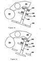
- a traditional mechanism for controlling the intake valve of an internal combustion engine is shown in Figs. 10 and 11, it mainly includes a cam 200, a rocker 300, a stopper 400 and a spring 500.
- One end of the rocker 300 engages the cam 200, the other end presses the stopper 400.
- One end of the spring 500 presses the support 700 which is fixedly secured with respect to the cylinder wall 600, the other end abuts against the flange 800 mounted on the end of the stopper 400.
- the cam 200 begins to rotate in clockwise direction from the position shown in Fig.
- a mechanism for controlling a valve of an internal combustion engine which comprises a cam, a rocker and a joining mechanism joining the rocker and a valve stem.
- the cam is formed on a crank shaft, the rocker may rock about an axis through its center and one side of the rocker has two arms forming a V-shape. Said two arms engage the cam and the other side of the rocker has only one arm.
- the cam has three protrusions which are arranged at an angle of 120° from each other. One of the two rocker arms engages the cam with a roller.
- the joining mechanism for joining the rocker and the valve stem is U-shaped and fixably secured to the valve stem.
- the U-shaped joining mechanism engages a rounded end of a rocker arm.
- the opening and closing of the valve is determined by the shape of the protrusions on the cam, these protrusions being triangular in shape. Since three identical protrusions are arranged at a distance from each other, the time for which the valve stays open at its maximum opening position is strictly limited to the time the roller takes to pass over the tip of each triangular protrusion.
- the object of the present invention is to provide a mechanism for controlling the intake valve of an internal combustion engine, which mechanism is capable of consuming less energy, i.e. less oil and which enables to keep the valve completely open for a larger span of the rotation angle of the crank shaft.
- this mechanism does not incur the spring resistance as opening the intake valve, thus the engine per se does not additionally consume energy, so that the object of reducing oil cost and promoting power output may be achieved.
- the mechanism for controlling the intake valve of an internal combustion engine comprises a cam, a rocker and a joining mechanism joining the rocker and the stopper.
- the cam is formed on the crank shaft, its shape is similar to ellipse.
- the rocker may rock about an axis through its center.
- One side of the rocker has two arms forming a "V" shape, said two arms engage the cam.
- the other side of the rocker has only one arm, the first cooperating part, the second cooperating part and the third cooperating part are formed in the end of this one arm.
- the joining mechanism includes the bottom plate, the spiral spring, the lower cooperating unit, the first connection element, the upper cooperating unit and the second connection element.
- the spiral spring is pressed between the lower cooperating unit and the bottom plate and its spring constant is comparatively small.
- the upper end of the stopper passes through the opening centered in the bottom plate and the inner hole of the spiral spring and is mounted on the lower cooperating unit.
- the lower cooperating unit and the upper cooperating unit are assembled together by means of the first connection element.
- the upper cooperating unit is capable of sliding with respect to the first connection element.
- the upper cooperating unit and the bottom plate are mounted together by means of the second connection element.
- the rocker rocks, and the second cooperating part will downwardly press the lower cooperating unit so that the stopper is pushed to open the intake valve.
- the third cooperating part will shift to engage the upper cooperating part.
- the other arm of the two arms will engage the cam, the rocker thus rocks in reverse direction, the third cooperating part will upwardly push the upper cooperating unit so that the intake valve is closed.
- the first cooperating part returns to engage the upper cooperating unit.
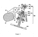
- the mechanism for controlling the intake valve of an internal combustion engine mainly includes a cam 10, a double-arm rocker 20 and a joining mechanism 100 joining the double-arm rocker and the stopper.
- the cam 10 is formed on the crank shaft and shaped similar to ellipse.
- the rocker 20 is mounted on a shaft 26.
- Two arms 21 and 22 are formed in one end of the rocker 20. The ends of two arms are rounded and engage the cam.
- the other end of the rocker 20 is uniquely shaped to form a first cooperating part 23, a second cooperating part 24 and a third cooperating part 25.
- the structure of the joining mechanism 100 is in the form of a frame.
- the joining mechanism 100 comprises a bottom plate 90, a spiral spring 40, a lower cooperating unit 110 , first connection elements 95, 95, an upper cooperating unit 120 and a second connection element 98, 98.
- the lower cooperating unit 110 comprises an intermediate support 50, a lower roller seat 60, a lower roller 65
- the upper cooperating unit 120 comprises an upper roller seat 70, an upper roller 75 and a top plate 80.
- the first connection elements are two pins 95, 95' whose longitudinal section is shaped as trapezoid.
- the second connection element are two bolts 98, 98'.
- the bottom plate 90 is made from thin metal plate such as steel plate and in a substantial round shape.
- An opening 97 is formed in the center of the bottom plate 90, and two flanges 99, 99' symmetrically protrude from the circumferential edge in the direction along one diameter.
- Two holes for inserting bolts are formed in the flanges 99, 99'.
- the main body of the intermediate support 50 is in a cylindrical shape, a cylindrical protrusion 51 protrudes around the central axis from the lower surface of the main body. This protrusion 51 inserts into the inner hole of the spring 40.
- One portion of the main body of the intermediate support 50 is cut away on the side adjacent to the cam 10 so that a slope 56 is formed to facilitate the movement of the rocker 20.
- a stepped hole 52 is formed in the intermediate support 50 around its central axis.
- a cuboid lower roller seat 60 is formed on the upper surface of the intermediate support 50.
- a protrusion 61 protrudes downwardly from the center of the lower surface of the lower roller seat 60.
- the two longitudinal sides of the protrusion 61 have circumferential shape which matches the shape of the upper larger hole of the stepped hole 52 in the intermediate support 50, moreover, the lower surface of the protrusion 61 presses on the upper end of the stopper.
- a cuboid recess 62 is formed in the upper surface of the lower roller seat 60 for receiving the lower roller 65.
- a steel pad 64 is placed on the bottom of the recess 62.
- the upper roller seat 70 also has a cuboid shape, and also a cuboid recess 72 is formed on the upper surface for receiving the upper roller 75.
- a slot 73 is cut out in the lower part of the upper roller seat 70 so that the upper roller is exposed for cooperating with the rocker.
- two stepped holes 53, 54 Adjacent to the outer circumference of the intermediate support 50, two stepped holes 53, 54 are symmetrically provided with their central axes parallel to the central axis of the intermediate support.
- two through holes 63, 66 concentric with the through holes 53, 54 are provided at the longitudinal end of the lower roller seat 60.
- two through holes 76, 77 concentric with the through holes 53, 54 are provided.
- the diameter of the through holes 63, 66 in the lower roller seat 60 is the same as the diameter of the smaller hole of the stepped holes 53, 54 in the intermediate support, the diameter of the through holes 76, 77 in the upper roller seat 70 is smaller than the diameter of the through holes 63, 66 in the upper roller seat 60.
- the intermediate support 50, the lower roller seat 60 and the upper roller seat 70 are assembled together by pins 95, 95' whose longitudinal section is trapezoid. The upper ends of pins protrude out after assembly.
- the top plate 80 is also made from thin metal plate such as steel plate and is in a substantial rectangular shape.
- the top plate is covered on the upper surface of the upper roller seat 70 by means of two holes 81, 82 in the top plate, said two holes 81, 82 are respectively located at two ends of one of the diagonal lines in the upper surface of the top plate. At two ends of the other diagonal lines, two bolt holes 83, 84 are provided.
- the top plate 80 and the bottom plate 90 are connected by two bolts 98, 98' passing through them.
- the middle segment of the bolt matches the circular recesses in the side walls of the intermediate support so as to secure the intermediate support.
- a stopper 30 being formed by a valve stem, passes through the hole 97 in the bottom plate 90 and the inner hole of the spiral spring 40 and is fitted in the smaller holes of the stepped hole 52 in the intermediate support 50 by means of a joint-element 31 separated into two halves and having a conical side surface.
- the bottom plate 90 is free with respect to the cylinder wall 150 of the internal combustion engine after the assembled mechanism for controlling the intake valve of an internal combustion engine according to the present invention is mounted in the engine. Namely, the bottom plate 90 is capable of moving unrestrictedly relative to the cylinder wall 150. This point is greatly different from the prior art in which the support 700 is fixedly mounted relative to the cylinder wall 600.
- the first cooperating part 23 of the rocker moves rightwards to cross over the upper roller 75 as shown in Fig. 4 so that the third cooperating part 25 engages the upper roller 75.
- the intake valve opens to the largest.
- the bottom plate 90 is free relative to the cylinder wall 150, therefore, there is no spring resistance when the stopper is opened, so the energy consumed by the engine per se may be reduced, namely, oil may be saved. Subsequently, as the cam further rotates to the position shown in Fig.
- the cam presses the arm 22 of the rocker downwardly, thus, the other end of the rocker rises and at the same time moves leftwards so that the third cooperating part 25 of the rocker applies an upward lift force which is transmitted via the top plate 80, the blots 98, the bottom plate 90, the spiral spring 40 and the intermediate support 50 to lift the stopper 30 so that the stopper 30 moves in the direction of closing.
- the cam continues to rotate, so the third cooperating part 25 of the rocker 20 compresses the spring 40 so as to apply greater force on the stopper 30 and thus closes the intake valve reliably.
- the rocker 20 moves leftwards as shown in Fig. 7, the upper roller 75 slides onto the first cooperating part 23 of the rocker so as to ensure the stopper is at the closed position.
- the cam continues its rotation, the above described course repeats.
- the mechanism for controlling the intake valve of an internal combustion engine according to the present invention has following advantages in addition to the advantage of saving oil: because no large force is applied, the cam and the rocker may be made quite small so as to reduce the dimension and weight. Moreover, because the resistance is small, the intake valve may be opened larger than the traditional design, this facilitates introducing more air under the high speed operation.
- the intake valve may be rapidly opened within 0° -40° of the rotation angle of the crank shaft, kept completely open within 40° -140° of the rotation angle of the crank shaft, and rapidly closed completely within 140° -180 of the rotation angle of the crank shaft.
- the opening time of the intake valve is extended, this results in more and faster intake so that the power output of the engine run at high speed is increased, the torque is enlarged, and the efficiency is improved.
- rollers 29, 29 may also be provided in the end of two arms of the rocker so that the engagement between the cam and the rocker is more smooth.
Landscapes
- Engineering & Computer Science (AREA)
- Mechanical Engineering (AREA)
- General Engineering & Computer Science (AREA)
- Valve Device For Special Equipments (AREA)
- Valve-Gear Or Valve Arrangements (AREA)
- Output Control And Ontrol Of Special Type Engine (AREA)
- Control Of Throttle Valves Provided In The Intake System Or In The Exhaust System (AREA)
- Exhaust Gas After Treatment (AREA)
- Fluid-Driven Valves (AREA)
Claims (3)
- Mécanisme destiné à commander une soupape d'admission d'un moteur à combustion interne comprenant une came (10), un culbuteur (20) et un mécanisme de jonction (100) reliant le culbuteur (20) et une butée (30), dans lequel la came (10) est formée sur un vilebrequin, le culbuteur (20) peut basculer autour d'un axe passant par son centre, un côté du culbuteur est pourvu de deux bras (21,22) formant un « V », lesdits deux bras engrènent avec la came (10), l'autre côté du culbuteur est pourvu d'un bras unique (28), caractérisé par le fait que la came (10) a approximativement la forme d'une ellipse, qu'une première pièce coopérante (23), une deuxième pièce coopérante (24) et une troisième pièce coopérante (25) sont formées à l'extrémité de ce bras unique (28), que de bas en haut, le mécanisme de jonction (100) comprend une plaque du bas (90), un ressort cylindrique (40), une unité coopérante inférieure (110), un premier élément de connexion (95, 95'), une unité coopérante supérieure (120) et un deuxième élément de connexion (98, 98') dans lequel la plaque du bas (90) est libre par rapport à une paroi du cylindre (150), le ressort cylindrique (40) étant comprimé entre l'unité coopérante inférieure (110) et la plaque du bas (90) et sa constante de rappel est relativement faible, que l'extrémité supérieure de la butée (30) passe à travers un orifice (97) au centre de la plaque du bas (90) et un trou intérieur du ressort cylindrique (40) et est montée sur l'unité coopérante inférieure (110), l'unité coopérante inférieure (110) et l'unité coopérante supérieure (120) étant assemblées par l'intermédiaire du premier élément de connexion (95, 95'), que l'unité coopérante supérieure (120) peut coulisser par rapport au premier élément de connexion (95, 95'), par ailleurs, l'unité coopérante supérieure (120) et la plaque du bas (90) sont montées ensemble par l'intermédiaire du deuxième élément de connexion (98, 98'), que dans la position initiale de chaque cycle, la came (10) engrène avec un bras (21) parmi les deux bras (21, 22) du culbuteur (20), que la première pièce coopérante (23) du culbuteur (20) engrène avec l'unité coopérante supérieure (120), que la deuxième pièce coopérante (24) du culbuteur (20) engrène avec l'unité coopérante inférieure (110), qu'en accompagnant la rotation de la came (10), le culbuteur (20) bascule et la deuxième pièce coopérante (24) pousse vers le bas l'unité coopérante inférieure (110) de façon à ce que l'ensemble du mécanisme de jonction (100) se décale vers le bas pour pousser la butée (30) pour ouvrir la soupape d'admission, qu'en outre, la troisième pièce coopérante (25) se déplace pour engrener avec l'unité coopérante supérieure (120), qu'en accompagnant la rotation continue de la came (10), l'autre bras (22) parmi les deux bras (21, 22) engrène avec la came (10), le culbuteur (20) bascule ainsi dans l'autre sens, la troisième pièce coopérante (25) pousse vers le haut l'unité coopérante supérieure (120) de telle façon que la soupape d'admission se ferme, qu'en outre la première pièce coopérante (23) revient engrener avec l'unité coopérante supérieure (120).
- Mécanisme destiné à commander la soupape d'admission d'un moteur à combustion interne selon la revendication 1, caractérisé par le fait que l'unité coopérante inférieure (110) comporte un support intermédiaire (50), un siège de galet inférieur (60), un galet inférieur (65), qu'un orifice (52) destiné au montage de l'extrémité de la butée (30) est pratiqué dans le support intermédiaire (50) autour de son axe central, le siège de galet inférieur (60) étant formé sur la face supérieure du support intermédiaire (50), un galet inférieur (65) est prévu dans le siège de galet inférieur (60), que la deuxième pièce coopérante (24) du culbuteur (20) engrène avec le galet inférieur (65), que l'unité coopérante supérieure (120) comprend un siège de galet supérieur (70), un galet supérieur (75), et une plaque du haut (80), qu'un galet supérieur (75) est prévu dans le siège de galet supérieur (70), que le galet supérieur (75) s'élève du fond du siège de galet supérieur (70) pour coopérer avec la première pièce coopérante (23) ou la troisième pièce coopérante (25) du culbuteur (20), que la plaque du haut (80) recouvre le siège de galet supérieur (70), que les premiers éléments de connexion sont deux broches (95, 95') dont la section longitudinale est trapézoïdale, les premiers éléments de connexion traversent des trous prévus dans le support intermédiaire (50), le siège de galet inférieur (60), le siège de galet supérieur (70) et la plaque du haut (80) de façon à les relier ensemble, les deuxièmes éléments de connexion sont deux boulons (98, 98') qui passent par les trous de boulon prévus dans la plaque du haut (80) et la plaque du bas (90) de façon à les relier ensemble.
- Mécanisme destiné à commander la soupape d'admission d'un moteur à combustion interne selon la revendication 1 ou 2, caractérisé par le fait que des galets (29, 29') peuvent être prévus à l'extrémité des deux bras (21, 22) du culbuteur (20).
Applications Claiming Priority (3)
| Application Number | Priority Date | Filing Date | Title |
|---|---|---|---|
| CN01100532 | 2001-01-20 | ||
| HK01100532A HK1033238A2 (en) | 2001-01-20 | 2001-01-20 | A control device for an air valve of an internal combustion engine |
| PCT/CN2001/001472 WO2002057601A1 (fr) | 2001-01-20 | 2001-10-09 | Dispositif de commande de soupape a air d'un moteur |
Publications (3)
| Publication Number | Publication Date |
|---|---|
| EP1353043A1 EP1353043A1 (fr) | 2003-10-15 |
| EP1353043A4 EP1353043A4 (fr) | 2004-07-14 |
| EP1353043B1 true EP1353043B1 (fr) | 2005-12-21 |
Family
ID=10945255
Family Applications (1)
| Application Number | Title | Priority Date | Filing Date |
|---|---|---|---|
| EP01273277A Expired - Lifetime EP1353043B1 (fr) | 2001-01-20 | 2001-10-09 | Dispositif de commande de soupape a air d'un moteur |
Country Status (13)
| Country | Link |
|---|---|
| US (1) | US6877469B2 (fr) |
| EP (1) | EP1353043B1 (fr) |
| KR (1) | KR100776123B1 (fr) |
| CN (1) | CN1227446C (fr) |
| AT (1) | ATE313701T1 (fr) |
| AU (1) | AU2002223414B2 (fr) |
| BR (1) | BR0116806A (fr) |
| CA (1) | CA2435019A1 (fr) |
| DE (2) | DE60116145T2 (fr) |
| HK (1) | HK1033238A2 (fr) |
| RU (1) | RU2274752C2 (fr) |
| WO (1) | WO2002057601A1 (fr) |
| ZA (1) | ZA200305573B (fr) |
Families Citing this family (10)
| Publication number | Priority date | Publication date | Assignee | Title |
|---|---|---|---|---|
| SE521189C2 (sv) * | 2002-02-04 | 2003-10-07 | Volvo Lastvagnar Ab | Anordning för att tillföra EGR-gas |
| US7870842B2 (en) * | 2008-04-07 | 2011-01-18 | Decuir Julian A | Engine with desmodromically actuated rocker |
| US20110239967A1 (en) * | 2010-03-30 | 2011-10-06 | Gnutti Ltd. | Valve bridge |
| DE102010018712B4 (de) * | 2010-04-29 | 2022-01-20 | Audi Ag | Ventiltrieb für ein Gaswechselventil mit Wälzkontakt zwischen Nockenfolger und Ventilschaft |
| JP2013164030A (ja) * | 2012-02-10 | 2013-08-22 | Aisin Seiki Co Ltd | エンジンのバルブ制御機構 |
| GB201307317D0 (en) * | 2013-04-23 | 2013-05-29 | Camcon Auto Ltd | Valve System and Methods of Operation Thereof |
| RU2557828C1 (ru) * | 2014-02-10 | 2015-07-27 | Закрытое Акционерное Общество "Диаконт" | Устройство для управления клапаном |
| JP2018035694A (ja) | 2016-08-29 | 2018-03-08 | スズキ株式会社 | エンジンの頭上弁作動機構 |
| CN108049258B (zh) * | 2017-12-26 | 2024-08-13 | 广东华工环源环保科技有限公司 | 一种应用于纸浆模塑成型的自动配气机构 |
| RU2679696C1 (ru) * | 2018-04-17 | 2019-02-12 | Александр Степанович Тимонин | Газораспределительный механизм |
Family Cites Families (24)
| Publication number | Priority date | Publication date | Assignee | Title |
|---|---|---|---|---|
| US1292215A (en) * | 1917-01-10 | 1919-01-21 | Joseph Zeitlin | Valve and valve-gear for internal-combustion and other engines. |
| US1491023A (en) * | 1919-02-24 | 1924-04-22 | Willys Overland Co | Valve-operating mechanism |
| FR590149A (fr) * | 1924-01-04 | 1925-06-11 | Système de commande pour les soupapes des moteurs à explosion et, en général, àcombustion interne | |
| US1612792A (en) * | 1924-02-21 | 1927-01-04 | Dorsey F Asbury | Valve-operating mechanism |
| US1633882A (en) * | 1924-11-17 | 1927-06-28 | Ballot Ernest Maurice | Valve-operating mechanism |
| GB242960A (en) * | 1924-11-17 | 1926-04-22 | Ets Ballot Sa | Improvements in or relating to the valve gear of internal-combustion engines |
| US1671973A (en) * | 1926-04-10 | 1928-06-05 | Russell T Anderson | Rocker arm and cam assembly for internal-combustion engines |
| GB343688A (en) * | 1930-01-13 | 1931-02-26 | Edward Ernest Morris | Improvements in positively operated valve gear for internal combustion engines |
| FR1029745A (fr) * | 1950-12-15 | 1953-06-05 | Perfectionnements apportés aux dispositifs à culbuteurs pour la commande de soupapes de moteurs à combustion interne | |
| US2751895A (en) * | 1952-05-20 | 1956-06-26 | Daimler Benz Ag | Valve control for internal combustion engines |
| US2954017A (en) * | 1958-03-29 | 1960-09-27 | Porsche Kg | Valve control arrangement for internal combustion engines |
| US3626469A (en) * | 1968-11-12 | 1971-12-07 | Gerald J Ashley | Valve gear |
| US3572299A (en) * | 1969-12-15 | 1971-03-23 | Lester Ind Inc | Valve-actuating train for machinery having a cyclicly operated poppet valve |
| DE2363891A1 (de) * | 1973-07-13 | 1975-06-26 | Daimler Benz Ag | Ventilverstellung fuer brennkraftmaschinen |
| FR2329847A1 (fr) * | 1975-10-31 | 1977-05-27 | Moteur Moderne Le | Dispositif de commande de soupape, notamment dans un moteur a arbre a cames en tete |
| US4141325A (en) * | 1976-12-23 | 1979-02-27 | Trw Inc. | Valve rotator |
| US4440121A (en) * | 1982-04-30 | 1984-04-03 | General Motors Corporation | Locknut device for engine rocker arm adjustment |
| EP0336259B1 (fr) * | 1988-03-28 | 1994-09-21 | Nissan Motor Co., Ltd. | Dispositif d'actionnement des soupapes champignons d'un moteur à combustion interne ou d'un type analogue |
| US5060606A (en) * | 1990-08-14 | 1991-10-29 | Camshaft Machine Company | Rocker arm |
| DE4334995C2 (de) * | 1993-10-14 | 1996-01-11 | Audi Ag | Ventiltrieb für eine Mehrzylinder-Brennkraftmaschine |
| US5806475A (en) * | 1996-03-22 | 1998-09-15 | Hausknecht; Louis A. | Low friction rocker arm assembly |
| US5782215A (en) | 1997-06-13 | 1998-07-21 | Engelmann; Mark M. | Intake/exhaust valve |
| US5791306A (en) * | 1997-08-13 | 1998-08-11 | Caterpillar Inc. | Internal combustion engine speed-throttle control |
| US6138624A (en) * | 1999-03-01 | 2000-10-31 | Cummins Engine Company, Inc. | Tappet socket assembly for rocker lever assembly and method of assembling the same |
-
2001
- 2001-01-20 HK HK01100532A patent/HK1033238A2/xx not_active IP Right Cessation
- 2001-10-09 RU RU2003125557/06A patent/RU2274752C2/ru active
- 2001-10-09 CN CNB018031536A patent/CN1227446C/zh not_active Expired - Fee Related
- 2001-10-09 WO PCT/CN2001/001472 patent/WO2002057601A1/fr not_active Ceased
- 2001-10-09 DE DE60116145T patent/DE60116145T2/de not_active Expired - Lifetime
- 2001-10-09 AT AT01273277T patent/ATE313701T1/de not_active IP Right Cessation
- 2001-10-09 BR BR0116806-1A patent/BR0116806A/pt not_active Application Discontinuation
- 2001-10-09 CA CA002435019A patent/CA2435019A1/fr not_active Abandoned
- 2001-10-09 DE DE10196588T patent/DE10196588T1/de not_active Withdrawn
- 2001-10-09 AU AU2002223414A patent/AU2002223414B2/en not_active Ceased
- 2001-10-09 KR KR1020037009534A patent/KR100776123B1/ko not_active Expired - Fee Related
- 2001-10-09 US US10/181,693 patent/US6877469B2/en not_active Expired - Fee Related
- 2001-10-09 EP EP01273277A patent/EP1353043B1/fr not_active Expired - Lifetime
-
2003
- 2003-07-18 ZA ZA2003/05573A patent/ZA200305573B/en unknown
Also Published As
| Publication number | Publication date |
|---|---|
| EP1353043A4 (fr) | 2004-07-14 |
| KR20030085520A (ko) | 2003-11-05 |
| ZA200305573B (en) | 2005-01-26 |
| BR0116806A (pt) | 2004-01-27 |
| RU2274752C2 (ru) | 2006-04-20 |
| DE10196588T1 (de) | 2003-12-18 |
| RU2003125557A (ru) | 2005-01-10 |
| EP1353043A1 (fr) | 2003-10-15 |
| CA2435019A1 (fr) | 2002-07-25 |
| US6877469B2 (en) | 2005-04-12 |
| US20030098001A1 (en) | 2003-05-29 |
| ATE313701T1 (de) | 2006-01-15 |
| JP2004520526A (ja) | 2004-07-08 |
| DE60116145D1 (de) | 2006-01-26 |
| JP3917075B2 (ja) | 2007-05-23 |
| CN1401048A (zh) | 2003-03-05 |
| WO2002057601A1 (fr) | 2002-07-25 |
| KR100776123B1 (ko) | 2007-11-15 |
| AU2002223414B2 (en) | 2006-09-28 |
| HK1033238A2 (en) | 2001-08-03 |
| CN1227446C (zh) | 2005-11-16 |
| DE60116145T2 (de) | 2006-08-17 |
Similar Documents
| Publication | Publication Date | Title |
|---|---|---|
| US7469669B2 (en) | Variable valve train mechanism of internal combustion engine | |
| EP1353043B1 (fr) | Dispositif de commande de soupape a air d'un moteur | |
| US7314029B2 (en) | Variable valve timing device adapted for internal combustion engine | |
| US7644689B2 (en) | Variable valve operating device | |
| JPH11294125A (ja) | 内燃機関の動弁装置 | |
| JP2006170188A (ja) | 可変カムシステム | |
| US20080115752A1 (en) | Engine valve lifter mechanism of internal combustion engine | |
| JP3917075B6 (ja) | 内燃機関の吸気バルブ制御機構 | |
| EP1422388A3 (fr) | Commande de soupape variable pour moteur à combustion interne | |
| KR100774636B1 (ko) | 가변밸브 리프트 팔로우워 장치 | |
| EP0125096A3 (fr) | Mécanisme pour le contrôle variable d'une soupape d'un moteur à combustion interne | |
| JP3901926B2 (ja) | 内燃機関の可変動弁装置 | |
| JPH0333414A (ja) | 4サイクルエンジンの動弁装置 | |
| KR19990010920A (ko) | 가변형 밸브 리프트 구조 | |
| US10233790B2 (en) | Variable valve mechanism of internal combustion engine | |
| JPS6325289Y2 (fr) | ||
| JPS5913283Y2 (ja) | 内燃機関の動弁機構 | |
| JP3833834B2 (ja) | 内燃機関の動弁装置 | |
| JPS6132087Y2 (fr) | ||
| KR200191590Y1 (ko) | 캠 | |
| JP2785603B2 (ja) | 内燃機関の吸・排気弁作動装置 | |
| US20070119400A1 (en) | Variable valve timing device adapted for internal combustion engine | |
| KR19980027808A (ko) | 스윙아암식 밸브개폐기구의 스윙아암구조 | |
| JPH07107362B2 (ja) | 内燃機関のバルブタイミング切換装置 | |
| KR19980066198U (ko) | 내연 기관의 벨브 개폐 장치 |
Legal Events
| Date | Code | Title | Description |
|---|---|---|---|
| PUAI | Public reference made under article 153(3) epc to a published international application that has entered the european phase |
Free format text: ORIGINAL CODE: 0009012 |
|
| 17P | Request for examination filed |
Effective date: 20030626 |
|
| AK | Designated contracting states |
Kind code of ref document: A1 Designated state(s): AT BE CH CY DE DK ES FI FR GB GR IE IT LI LU MC NL PT SE TR |
|
| AX | Request for extension of the european patent |
Extension state: AL LT LV MK RO SI |
|
| A4 | Supplementary search report drawn up and despatched |
Effective date: 20040602 |
|
| RIC1 | Information provided on ipc code assigned before grant |
Ipc: 7F 01L 1/30 A |
|
| 17Q | First examination report despatched |
Effective date: 20040901 |
|
| GRAP | Despatch of communication of intention to grant a patent |
Free format text: ORIGINAL CODE: EPIDOSNIGR1 |
|
| GRAS | Grant fee paid |
Free format text: ORIGINAL CODE: EPIDOSNIGR3 |
|
| GRAA | (expected) grant |
Free format text: ORIGINAL CODE: 0009210 |
|
| AK | Designated contracting states |
Kind code of ref document: B1 Designated state(s): AT BE CH CY DE DK ES FI FR GB GR IE IT LI LU MC NL PT SE TR |
|
| PG25 | Lapsed in a contracting state [announced via postgrant information from national office to epo] |
Ref country code: IT Free format text: LAPSE BECAUSE OF FAILURE TO SUBMIT A TRANSLATION OF THE DESCRIPTION OR TO PAY THE FEE WITHIN THE PRESCRIBED TIME-LIMIT;WARNING: LAPSES OF ITALIAN PATENTS WITH EFFECTIVE DATE BEFORE 2007 MAY HAVE OCCURRED AT ANY TIME BEFORE 2007. THE CORRECT EFFECTIVE DATE MAY BE DIFFERENT FROM THE ONE RECORDED. Effective date: 20051221 Ref country code: BE Free format text: LAPSE BECAUSE OF FAILURE TO SUBMIT A TRANSLATION OF THE DESCRIPTION OR TO PAY THE FEE WITHIN THE PRESCRIBED TIME-LIMIT Effective date: 20051221 Ref country code: CH Free format text: LAPSE BECAUSE OF FAILURE TO SUBMIT A TRANSLATION OF THE DESCRIPTION OR TO PAY THE FEE WITHIN THE PRESCRIBED TIME-LIMIT Effective date: 20051221 Ref country code: AT Free format text: LAPSE BECAUSE OF FAILURE TO SUBMIT A TRANSLATION OF THE DESCRIPTION OR TO PAY THE FEE WITHIN THE PRESCRIBED TIME-LIMIT Effective date: 20051221 Ref country code: FI Free format text: LAPSE BECAUSE OF FAILURE TO SUBMIT A TRANSLATION OF THE DESCRIPTION OR TO PAY THE FEE WITHIN THE PRESCRIBED TIME-LIMIT Effective date: 20051221 Ref country code: NL Free format text: LAPSE BECAUSE OF FAILURE TO SUBMIT A TRANSLATION OF THE DESCRIPTION OR TO PAY THE FEE WITHIN THE PRESCRIBED TIME-LIMIT Effective date: 20051221 Ref country code: LI Free format text: LAPSE BECAUSE OF FAILURE TO SUBMIT A TRANSLATION OF THE DESCRIPTION OR TO PAY THE FEE WITHIN THE PRESCRIBED TIME-LIMIT Effective date: 20051221 |
|
| REG | Reference to a national code |
Ref country code: GB Ref legal event code: FG4D |
|
| REG | Reference to a national code |
Ref country code: CH Ref legal event code: EP |
|
| REG | Reference to a national code |
Ref country code: IE Ref legal event code: FG4D |
|
| REF | Corresponds to: |
Ref document number: 60116145 Country of ref document: DE Date of ref document: 20060126 Kind code of ref document: P |
|
| PG25 | Lapsed in a contracting state [announced via postgrant information from national office to epo] |
Ref country code: GR Free format text: LAPSE BECAUSE OF FAILURE TO SUBMIT A TRANSLATION OF THE DESCRIPTION OR TO PAY THE FEE WITHIN THE PRESCRIBED TIME-LIMIT Effective date: 20060321 Ref country code: SE Free format text: LAPSE BECAUSE OF FAILURE TO SUBMIT A TRANSLATION OF THE DESCRIPTION OR TO PAY THE FEE WITHIN THE PRESCRIBED TIME-LIMIT Effective date: 20060321 Ref country code: DK Free format text: LAPSE BECAUSE OF FAILURE TO SUBMIT A TRANSLATION OF THE DESCRIPTION OR TO PAY THE FEE WITHIN THE PRESCRIBED TIME-LIMIT Effective date: 20060321 |
|
| PG25 | Lapsed in a contracting state [announced via postgrant information from national office to epo] |
Ref country code: ES Free format text: LAPSE BECAUSE OF FAILURE TO SUBMIT A TRANSLATION OF THE DESCRIPTION OR TO PAY THE FEE WITHIN THE PRESCRIBED TIME-LIMIT Effective date: 20060401 |
|
| PG25 | Lapsed in a contracting state [announced via postgrant information from national office to epo] |
Ref country code: PT Free format text: LAPSE BECAUSE OF FAILURE TO SUBMIT A TRANSLATION OF THE DESCRIPTION OR TO PAY THE FEE WITHIN THE PRESCRIBED TIME-LIMIT Effective date: 20060522 |
|
| NLV1 | Nl: lapsed or annulled due to failure to fulfill the requirements of art. 29p and 29m of the patents act | ||
| REG | Reference to a national code |
Ref country code: CH Ref legal event code: PL |
|
| ET | Fr: translation filed | ||
| PG25 | Lapsed in a contracting state [announced via postgrant information from national office to epo] |
Ref country code: IE Free format text: LAPSE BECAUSE OF NON-PAYMENT OF DUE FEES Effective date: 20061009 |
|
| PLBE | No opposition filed within time limit |
Free format text: ORIGINAL CODE: 0009261 |
|
| STAA | Information on the status of an ep patent application or granted ep patent |
Free format text: STATUS: NO OPPOSITION FILED WITHIN TIME LIMIT |
|
| PG25 | Lapsed in a contracting state [announced via postgrant information from national office to epo] |
Ref country code: MC Free format text: LAPSE BECAUSE OF NON-PAYMENT OF DUE FEES Effective date: 20061031 |
|
| 26N | No opposition filed |
Effective date: 20060922 |
|
| REG | Reference to a national code |
Ref country code: IE Ref legal event code: MM4A |
|
| PG25 | Lapsed in a contracting state [announced via postgrant information from national office to epo] |
Ref country code: LU Free format text: LAPSE BECAUSE OF NON-PAYMENT OF DUE FEES Effective date: 20061009 Ref country code: TR Free format text: LAPSE BECAUSE OF FAILURE TO SUBMIT A TRANSLATION OF THE DESCRIPTION OR TO PAY THE FEE WITHIN THE PRESCRIBED TIME-LIMIT Effective date: 20051221 |
|
| PG25 | Lapsed in a contracting state [announced via postgrant information from national office to epo] |
Ref country code: CY Free format text: LAPSE BECAUSE OF FAILURE TO SUBMIT A TRANSLATION OF THE DESCRIPTION OR TO PAY THE FEE WITHIN THE PRESCRIBED TIME-LIMIT Effective date: 20051221 |
|
| PGFP | Annual fee paid to national office [announced via postgrant information from national office to epo] |
Ref country code: FR Payment date: 20121018 Year of fee payment: 12 Ref country code: DE Payment date: 20121003 Year of fee payment: 12 |
|
| PGFP | Annual fee paid to national office [announced via postgrant information from national office to epo] |
Ref country code: IT Payment date: 20121012 Year of fee payment: 12 Ref country code: GB Payment date: 20121003 Year of fee payment: 12 |
|
| GBPC | Gb: european patent ceased through non-payment of renewal fee |
Effective date: 20131009 |
|
| PG25 | Lapsed in a contracting state [announced via postgrant information from national office to epo] |
Ref country code: GB Free format text: LAPSE BECAUSE OF NON-PAYMENT OF DUE FEES Effective date: 20131009 |
|
| REG | Reference to a national code |
Ref country code: FR Ref legal event code: ST Effective date: 20140630 |
|
| REG | Reference to a national code |
Ref country code: DE Ref legal event code: R119 Ref document number: 60116145 Country of ref document: DE Effective date: 20140501 |
|
| PG25 | Lapsed in a contracting state [announced via postgrant information from national office to epo] |
Ref country code: FR Free format text: LAPSE BECAUSE OF NON-PAYMENT OF DUE FEES Effective date: 20131031 Ref country code: DE Free format text: LAPSE BECAUSE OF NON-PAYMENT OF DUE FEES Effective date: 20140501 Ref country code: IT Free format text: LAPSE BECAUSE OF NON-PAYMENT OF DUE FEES Effective date: 20131009 |