EP1353046A1 - Vorrichtung und Verfahren zur Abgasreinigung für eine Brennkraftmaschine - Google Patents
Vorrichtung und Verfahren zur Abgasreinigung für eine Brennkraftmaschine Download PDFInfo
- Publication number
- EP1353046A1 EP1353046A1 EP03007977A EP03007977A EP1353046A1 EP 1353046 A1 EP1353046 A1 EP 1353046A1 EP 03007977 A EP03007977 A EP 03007977A EP 03007977 A EP03007977 A EP 03007977A EP 1353046 A1 EP1353046 A1 EP 1353046A1
- Authority
- EP
- European Patent Office
- Prior art keywords
- filter
- exhaust
- dpf
- particulate matter
- diameter
- Prior art date
- Legal status (The legal status is an assumption and is not a legal conclusion. Google has not performed a legal analysis and makes no representation as to the accuracy of the status listed.)
- Withdrawn
Links
Images





Classifications
-
- F—MECHANICAL ENGINEERING; LIGHTING; HEATING; WEAPONS; BLASTING
- F01—MACHINES OR ENGINES IN GENERAL; ENGINE PLANTS IN GENERAL; STEAM ENGINES
- F01N—GAS-FLOW SILENCERS OR EXHAUST APPARATUS FOR MACHINES OR ENGINES IN GENERAL; GAS-FLOW SILENCERS OR EXHAUST APPARATUS FOR INTERNAL-COMBUSTION ENGINES
- F01N3/00—Exhaust or silencing apparatus having means for purifying, rendering innocuous, or otherwise treating exhaust
- F01N3/02—Exhaust or silencing apparatus having means for purifying, rendering innocuous, or otherwise treating exhaust for cooling, or for removing solid constituents of, exhaust
- F01N3/021—Exhaust or silencing apparatus having means for purifying, rendering innocuous, or otherwise treating exhaust for cooling, or for removing solid constituents of, exhaust by means of filters
-
- F—MECHANICAL ENGINEERING; LIGHTING; HEATING; WEAPONS; BLASTING
- F01—MACHINES OR ENGINES IN GENERAL; ENGINE PLANTS IN GENERAL; STEAM ENGINES
- F01N—GAS-FLOW SILENCERS OR EXHAUST APPARATUS FOR MACHINES OR ENGINES IN GENERAL; GAS-FLOW SILENCERS OR EXHAUST APPARATUS FOR INTERNAL-COMBUSTION ENGINES
- F01N13/00—Exhaust or silencing apparatus characterised by constructional features
- F01N13/009—Exhaust or silencing apparatus characterised by constructional features having two or more separate purifying devices arranged in series
-
- F—MECHANICAL ENGINEERING; LIGHTING; HEATING; WEAPONS; BLASTING
- F01—MACHINES OR ENGINES IN GENERAL; ENGINE PLANTS IN GENERAL; STEAM ENGINES
- F01N—GAS-FLOW SILENCERS OR EXHAUST APPARATUS FOR MACHINES OR ENGINES IN GENERAL; GAS-FLOW SILENCERS OR EXHAUST APPARATUS FOR INTERNAL-COMBUSTION ENGINES
- F01N13/00—Exhaust or silencing apparatus characterised by constructional features
- F01N13/009—Exhaust or silencing apparatus characterised by constructional features having two or more separate purifying devices arranged in series
- F01N13/0093—Exhaust or silencing apparatus characterised by constructional features having two or more separate purifying devices arranged in series the purifying devices are of the same type
-
- F—MECHANICAL ENGINEERING; LIGHTING; HEATING; WEAPONS; BLASTING
- F01—MACHINES OR ENGINES IN GENERAL; ENGINE PLANTS IN GENERAL; STEAM ENGINES
- F01N—GAS-FLOW SILENCERS OR EXHAUST APPARATUS FOR MACHINES OR ENGINES IN GENERAL; GAS-FLOW SILENCERS OR EXHAUST APPARATUS FOR INTERNAL-COMBUSTION ENGINES
- F01N3/00—Exhaust or silencing apparatus having means for purifying, rendering innocuous, or otherwise treating exhaust
- F01N3/02—Exhaust or silencing apparatus having means for purifying, rendering innocuous, or otherwise treating exhaust for cooling, or for removing solid constituents of, exhaust
- F01N3/021—Exhaust or silencing apparatus having means for purifying, rendering innocuous, or otherwise treating exhaust for cooling, or for removing solid constituents of, exhaust by means of filters
- F01N3/022—Exhaust or silencing apparatus having means for purifying, rendering innocuous, or otherwise treating exhaust for cooling, or for removing solid constituents of, exhaust by means of filters characterised by specially adapted filtering structure, e.g. honeycomb, mesh or fibrous
- F01N3/0222—Exhaust or silencing apparatus having means for purifying, rendering innocuous, or otherwise treating exhaust for cooling, or for removing solid constituents of, exhaust by means of filters characterised by specially adapted filtering structure, e.g. honeycomb, mesh or fibrous the structure being monolithic, e.g. honeycombs
-
- F—MECHANICAL ENGINEERING; LIGHTING; HEATING; WEAPONS; BLASTING
- F01—MACHINES OR ENGINES IN GENERAL; ENGINE PLANTS IN GENERAL; STEAM ENGINES
- F01N—GAS-FLOW SILENCERS OR EXHAUST APPARATUS FOR MACHINES OR ENGINES IN GENERAL; GAS-FLOW SILENCERS OR EXHAUST APPARATUS FOR INTERNAL-COMBUSTION ENGINES
- F01N2250/00—Combinations of different methods of purification
- F01N2250/02—Combinations of different methods of purification filtering and catalytic conversion
-
- F—MECHANICAL ENGINEERING; LIGHTING; HEATING; WEAPONS; BLASTING
- F01—MACHINES OR ENGINES IN GENERAL; ENGINE PLANTS IN GENERAL; STEAM ENGINES
- F01N—GAS-FLOW SILENCERS OR EXHAUST APPARATUS FOR MACHINES OR ENGINES IN GENERAL; GAS-FLOW SILENCERS OR EXHAUST APPARATUS FOR INTERNAL-COMBUSTION ENGINES
- F01N2330/00—Structure of catalyst support or particle filter
- F01N2330/06—Ceramic, e.g. monoliths
-
- F—MECHANICAL ENGINEERING; LIGHTING; HEATING; WEAPONS; BLASTING
- F01—MACHINES OR ENGINES IN GENERAL; ENGINE PLANTS IN GENERAL; STEAM ENGINES
- F01N—GAS-FLOW SILENCERS OR EXHAUST APPARATUS FOR MACHINES OR ENGINES IN GENERAL; GAS-FLOW SILENCERS OR EXHAUST APPARATUS FOR INTERNAL-COMBUSTION ENGINES
- F01N2340/00—Dimensional characteristics of the exhaust system, e.g. length, diameter or volume of the exhaust apparatus; Spatial arrangements of exhaust apparatuses
- F01N2340/04—Arrangement of the exhaust system relative to a vehicle or parts thereof
-
- F—MECHANICAL ENGINEERING; LIGHTING; HEATING; WEAPONS; BLASTING
- F01—MACHINES OR ENGINES IN GENERAL; ENGINE PLANTS IN GENERAL; STEAM ENGINES
- F01N—GAS-FLOW SILENCERS OR EXHAUST APPARATUS FOR MACHINES OR ENGINES IN GENERAL; GAS-FLOW SILENCERS OR EXHAUST APPARATUS FOR INTERNAL-COMBUSTION ENGINES
- F01N3/00—Exhaust or silencing apparatus having means for purifying, rendering innocuous, or otherwise treating exhaust
- F01N3/02—Exhaust or silencing apparatus having means for purifying, rendering innocuous, or otherwise treating exhaust for cooling, or for removing solid constituents of, exhaust
- F01N3/021—Exhaust or silencing apparatus having means for purifying, rendering innocuous, or otherwise treating exhaust for cooling, or for removing solid constituents of, exhaust by means of filters
- F01N3/023—Exhaust or silencing apparatus having means for purifying, rendering innocuous, or otherwise treating exhaust for cooling, or for removing solid constituents of, exhaust by means of filters using means for regenerating the filters, e.g. by burning trapped particles
-
- F—MECHANICAL ENGINEERING; LIGHTING; HEATING; WEAPONS; BLASTING
- F01—MACHINES OR ENGINES IN GENERAL; ENGINE PLANTS IN GENERAL; STEAM ENGINES
- F01N—GAS-FLOW SILENCERS OR EXHAUST APPARATUS FOR MACHINES OR ENGINES IN GENERAL; GAS-FLOW SILENCERS OR EXHAUST APPARATUS FOR INTERNAL-COMBUSTION ENGINES
- F01N3/00—Exhaust or silencing apparatus having means for purifying, rendering innocuous, or otherwise treating exhaust
- F01N3/02—Exhaust or silencing apparatus having means for purifying, rendering innocuous, or otherwise treating exhaust for cooling, or for removing solid constituents of, exhaust
- F01N3/021—Exhaust or silencing apparatus having means for purifying, rendering innocuous, or otherwise treating exhaust for cooling, or for removing solid constituents of, exhaust by means of filters
- F01N3/033—Exhaust or silencing apparatus having means for purifying, rendering innocuous, or otherwise treating exhaust for cooling, or for removing solid constituents of, exhaust by means of filters in combination with other devices
- F01N3/035—Exhaust or silencing apparatus having means for purifying, rendering innocuous, or otherwise treating exhaust for cooling, or for removing solid constituents of, exhaust by means of filters in combination with other devices with catalytic reactors
-
- F—MECHANICAL ENGINEERING; LIGHTING; HEATING; WEAPONS; BLASTING
- F02—COMBUSTION ENGINES; HOT-GAS OR COMBUSTION-PRODUCT ENGINE PLANTS
- F02B—INTERNAL-COMBUSTION PISTON ENGINES; COMBUSTION ENGINES IN GENERAL
- F02B29/00—Engines characterised by provision for charging or scavenging not provided for in groups F02B25/00, F02B27/00 or F02B33/00 - F02B39/00; Details thereof
- F02B29/04—Cooling of air intake supply
-
- F—MECHANICAL ENGINEERING; LIGHTING; HEATING; WEAPONS; BLASTING
- F02—COMBUSTION ENGINES; HOT-GAS OR COMBUSTION-PRODUCT ENGINE PLANTS
- F02B—INTERNAL-COMBUSTION PISTON ENGINES; COMBUSTION ENGINES IN GENERAL
- F02B37/00—Engines characterised by provision of pumps driven at least for part of the time by exhaust
-
- Y—GENERAL TAGGING OF NEW TECHNOLOGICAL DEVELOPMENTS; GENERAL TAGGING OF CROSS-SECTIONAL TECHNOLOGIES SPANNING OVER SEVERAL SECTIONS OF THE IPC; TECHNICAL SUBJECTS COVERED BY FORMER USPC CROSS-REFERENCE ART COLLECTIONS [XRACs] AND DIGESTS
- Y02—TECHNOLOGIES OR APPLICATIONS FOR MITIGATION OR ADAPTATION AGAINST CLIMATE CHANGE
- Y02T—CLIMATE CHANGE MITIGATION TECHNOLOGIES RELATED TO TRANSPORTATION
- Y02T10/00—Road transport of goods or passengers
- Y02T10/10—Internal combustion engine [ICE] based vehicles
- Y02T10/12—Improving ICE efficiencies
Definitions
- the present invention relates to an apparatus for purifying an exhaust gas in an engine and in particular, for trapping and burning particulate matter in the exhaust gas.
- a front filter and a rear filter are disposed in a single filter casing.
- the front filter has bores adapted to trap particulate matter having a large diameter and the rear filter has bores adapted to trap particulate matter having a small diameter.
- this filter housing has a capacity enough for receiving two filters and therefore, it is difficult to find space enough for positioning the filter casing close to an exhaust manifold having a high exhaust gas temperature in an engine hood.
- the capacity of the rear filter is required to be large and accordingly, it is more difficult to find space around the engine for attaching the filter casing receiving two filters.
- the present invention provides an apparatus for purifying an exhaust gas of an engine to solve the foregoing problems.
- one aspect of the invention provides an apparatus of disposing a first filter in an upstream side of the exhaust passage to trap particulate matter having at least a first diameter and disposing a second filter in a downstream side of the exhaust passage to trap particulate matter having at least a second diameter, the second diameter smaller than the first diameter.
- Fig. 1 is a system view of a diesel engine showing a first embodiment of the invention.
- Air is aspired into a combustion chamber 2 of each cylinder in a diesel engine 1 through an intake system such as an air cleaner 3, an intake compressor 4 of a turbocharger, an intercooler 5, an intake throttle valve 6, and an intake manifold 7.
- An injector 8 directly injects fuel into combustion chamber 2 where the mixture thereof burns by compression ignition.
- An exhaust gas after the combustion is discharged from an exhaust manifold 9a connected to a cylinder head of engine 1 and an exhaust pipe 9b connected thereto, which drives an exhaust turbine 10 of the turbocharger disposed in exhaust pipe 9b.
- a particulate filter 11 a with a first mesh size (large mesh size) is contained in a casing 11a that traps particulate matter having a large diameter and a particulate 12a filter with a second mesh size (small mesh size) is contained in a casing 12a that traps particulate matter having a small diameter are separately disposed as a diesel particulate filter (DPF hereinafter) in an exhaust passage where the particulate matter trapped burns in order to purify the particulate matter in the exhaust gas discharged from diesel engine 1.
- DPF diesel particulate filter
- the bores of the large mesh size are not necessarily larger than the bores of the small mesh size, but the bores of the large mesh size are adapted to trap particulate matter having a larger diameter and the bores of the small mesh size are adapted to trap particulate matter having a small diameter.
- DPF 11 a is directly connected to exhaust manifold 9a upstream of exhaust turbine 10. DPF 11 a may be disposed close to exhaust manifold 9a.
- DPF 12a is positioned in exhaust pipe 9b and at a location away from exhaust manifold 9a (namely, downstream of exhaust turbine 10).
- An exhaust passage 9 includes exhaust manifold 9a, DPF 11a, exhaust turbine 10 of the turbocharger, DPF 12a, and exhaust pipe 9b.
- Fig. 2 is a layout view of the first embodiment-mount vehicle where DPF 11a is disposed in an engine hood.
- D in the figure shows a dash panel that is a partition wall between a front side and a rear side of the engine hood and R in the figure shows a radiator disposed in the front side of the engine hood.
- DPF 12a is disposed in the middle of an exhaust pipe 9b extending along and under a vehicle floor from engine 1 toward a vehicle rear side, and a flexible tube F and a ball coupling (not shown) included in exhaust passage 9 are used for its connection.
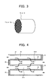
- DPF 11a with the large mesh size and DPF 12a with the small mesh size will be explained in detail. First, the points common in both DPF 11a and DPF 12a will be explained. DPF 11a and DPF 12a both are formed of porous ceramic and honeycomb structure having a circular shape, and received in a cylindrical housing (not shown) through a holding mat.
- a plurality of parallel cell spaces 22 are formed being partitioned by porous latticed cell walls 21 made of honeycomb-structure ceramic and each cell space extends toward an exhaust gas flow direction.
- an outlet of one cell space is closed by a sealing member 23 and an inlet of the other neighboring cell space is closed by a sealing member 24 alternately.
- Cell space 22 where the inlet is open and the outlet is closed by the sealing member 23 is an exhaust gas - inflow cell space 22A and cell space 22 where the inlet is closed by sealing member 24 and the outlet is open is an exhaust gas - outflow cell space 22B.
- An exhaust gas from engine 1 flows into cell space 22A and outflows into cell space 22B only through porous cell wall 21 (its air hole). Therefore, cell wall 21 can certainly trap the particulate matter in the exhaust gas.
- An inner surface of cell wall 21 facing cell space 22A is coated with a catalyst including precious medals such as Pt, Pd, Rh and the like to form a catalyst layer 25 and thereby, along with trapping the particulate matter in the exhaust gas, due to catalyst effect, oxidization of HC and CO in the exhaust gas is prompted and these HC and CO can be purified. And also the deposited particulate matter can be burned and removed under oxygen in the exhaust gas by the particulate matter being heated due to its reaction heat.
- a catalyst including precious medals such as Pt, Pd, Rh and the like
- DPF 11a with large mesh size can trap the particulate matter in a relatively large diameter and has a relatively small flow resistance and DPF with small mesh size can trap the particulate matter in a relatively small diameter and has a relatively large flow resistance.
- Fig. 5 (a) shows an enlarged cross section view of a lattice cell wall 21 of DPF 11a with the first mesh size and Fig. (b) or(c) shows an enlarged cross section view of lattice cell wall 21 of DPF 12a.
- Lattice cell wall 21 of DPF 11a can trap the particulate matter in 80 -100 nm of a particle diameter by enlarging an averaging bore diameter of the air bores.
- lattice cell wall 21 of DPF 12a with the second mesh size can trap the particulate matter in 20 -50 nm of a particle diameter by reducing an averaging bore diameter of the air bores or, as shown in Fig. 5 (c), can trap the particulate matter by increasing a wall thickness thereof to enlarge a passing length or a contact surface area thereof without changing an averaging bore diameter of the air bores to DPF 11a in Fig. 5 (a).
- Large mesh size and small mesh size may be formed by selection of a material (fabric ceramic, foam metal) in addition of change of the air bore diameter or the wall thickness.
- V 1 is set as a value less than V 2.
- V 1 is set as a value less than V 2.
- DPF 11a and DPF 12a have the same capacity, and a total capacity of the flow paths in the small mesh size is smaller than in the large mesh size and thereby, the small mesh size have more flow resistance than the large mesh size. Accordingly in order to make the flow resistance or total capacity of the flow paths in DPF 11a to be equal to that of the DPF 12a it is desirable to increase the capacity of DPF 12a with small mesh size compared with DPF 11a with large mesh size.
- Pressure loss is an important factor and a pressure loss of an engine is determined by the largest pressure loss among pressure resistance factors in the exhaust system and therefore, no difference in the pressure loss between DPF 11a and DPF 12a is preferable.
- DPF 11a with large mesh size that traps particulate matter in a relatively large diameter is disposed around exhaust manifold 9 and therefore, it is sufficient only if DPF 12a with small mesh size downstream of DPF 11a traps particulate matter in a relatively small diameter.
- DPF 11a traps particulate matter in a relatively large diameter in the vicinity of exhaust manifold 9 in a high temperature atmosphere and therefore, even if a diameter of the particulate matter trapped is large, the particulate matter can be burned properly, thereby promoting regeneration efficiency.
- Fig. 7 showing a relation between particulate matter diameter and oxidization temperature
- the oxidization temperature is lower and therefore, even when the DPF is positioned under a vehicle body floor away from an engine, the particulate matter can burn.
- Fig. 8 showing a relation between DPF capacity and DPF pressure loss
- the pressure loss becomes smaller.
- Fig. 9 showing a relation between a diameter of a particulate matter to be able to be trapped and DPF pressure loss, as a particle diameter to be able to be trapped becomes larger, a flow resistance thereof becomes smaller and thereby the pressure loss becomes small.
- DPF 11a that can traps particulate matter in a large diameter, as seen in Fig. 9, when the pressure loss is small, and even if the pressure loss increases due to reducing a capacity of DPF 11a as seen in Fig. 8, a total pressure can be maintained at a certain level.
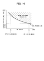
- DPF 11a capacity and a diameter of the particulate matter to be able to be trapped as a parameter in Fig. 10, since in a case of DPF 11a the diameter of the particulate matter to be able to be trapped is large, DPF capacity can be reduced.
- a small capacity of DPF 11a can be used and a small space for receiving DPF 11a can be used, enabling positioning DPF 11a in the vicinity of engine 1 which has a small space.
- DPF 12a with small mesh size that traps particulate matter in a relatively small diameter is positioned in a downstream side away from the vicinity of exhaust manifold 9 and DPF 11a in the upstream side traps the particulate matter in a large diameter. Therefore, since DPF 12a traps only the particulate matter in a small diameter that does not require a high temperature for its burning, it is not difficult to burn.
- DPF 12a a tolerance pressure loss can be maintained to a certain level by increasing the DPF capacity corresponding to a particle diameter of the particle matter for trap being small. Although this increase of the DPF capacity requires more space, there is no problem with it because there is space for accommodating DPF 12a under a vehicle floor.
- a particulate filter with large mesh size that traps particulate matter having a relatively large diameter is disposed in the vicinity of an exhaust manifold and on the other hand, a particulate filter with small mesh size that traps particulate matter having a relatively small diameter is dispose in a downstream side away from the vicinity of the exhaust manifold.
- the embodiment can provides an exhaust purification apparatus that has an excellent quality in terms of regeneration efficiency, pressure loss, and space of a particulate filter.
- a particulate filter with large mesh size is disposed upstream of an exhaust gas turbine.
- regeneration efficiency thereof can be improved by making use of a high-temperature exhaust gas prior to a temperature decrease thereof caused by the exhaust gas turbine.
- a capacity (V1) of a particulate filter with large mesh size having a small flow resistance is made small and a capacity of a particulate filter with small mesh size having a large flow resistance is made large (V2 ; V2 > V1).
- each of a particulate filter with large mesh size and a particulate filter with small mesh size has a catalyst by which oxidization of HC and CO in the exhaust gas is promoted. Therefore, the particulate matter can be properly burned by using reaction heat thereof.
- DPF 11a is disposed upstream of exhaust gas turbine 10 whereby the regeneration efficiency of DPF 11a can be improved by making use of the high-temperature exhaust gas prior to the temperature decrease caused by exhaust gas turbine 10.
- a turbocharger performance may deteriorate if a distance between an engine and the turbocharger is lengthened.
- DPF 11a is disposed immediately downstream of exhaust gas turbine 10. thereby regeneration efficiency of DPF 11a can be properly maintained by using a high-temperature exhaust gas as much as possible in a relatively spacious location without deteriorating a turbocharger performance.
- DPF 11a can be disposed in the engine hood and DPF 12a can be disposed under a vehicle floor.
Landscapes
- Engineering & Computer Science (AREA)
- Chemical & Material Sciences (AREA)
- Combustion & Propulsion (AREA)
- Mechanical Engineering (AREA)
- General Engineering & Computer Science (AREA)
- Processes For Solid Components From Exhaust (AREA)
- Filtering Of Dispersed Particles In Gases (AREA)
- Exhaust Gas After Treatment (AREA)
- Exhaust Gas Treatment By Means Of Catalyst (AREA)
Applications Claiming Priority (2)
| Application Number | Priority Date | Filing Date | Title |
|---|---|---|---|
| JP2002106683 | 2002-04-09 | ||
| JP2002106683A JP2003301713A (ja) | 2002-04-09 | 2002-04-09 | エンジンの排気浄化装置 |
Publications (1)
| Publication Number | Publication Date |
|---|---|
| EP1353046A1 true EP1353046A1 (de) | 2003-10-15 |
Family
ID=28449926
Family Applications (1)
| Application Number | Title | Priority Date | Filing Date |
|---|---|---|---|
| EP03007977A Withdrawn EP1353046A1 (de) | 2002-04-09 | 2003-04-09 | Vorrichtung und Verfahren zur Abgasreinigung für eine Brennkraftmaschine |
Country Status (3)
| Country | Link |
|---|---|
| US (1) | US20030213231A1 (de) |
| EP (1) | EP1353046A1 (de) |
| JP (1) | JP2003301713A (de) |
Cited By (12)
| Publication number | Priority date | Publication date | Assignee | Title |
|---|---|---|---|---|
| EP1596046A1 (de) * | 2004-05-14 | 2005-11-16 | Ford Global Technologies, LLC, A subsidary of Ford Motor Company | Anordnung und Verfahren zur Regeneration eines Dieselpartikelfilters |
| WO2006029808A1 (de) * | 2004-09-17 | 2006-03-23 | Arvinmeritor Emissions Technologies Gmbh | Abgasanlage eines kfzs mit dieselmotor |
| WO2006037703A1 (de) * | 2004-10-05 | 2006-04-13 | Robert Bosch Gmbh | Abgassystem für eine brennkraftmaschine, sowie verfahren zum betreiben eines solchen abgassystems |
| WO2008066767A1 (en) | 2006-11-29 | 2008-06-05 | Corning Incorporated | Partial wall-flow filter and diesel exhaust system and method |
| KR100882371B1 (ko) | 2000-10-31 | 2009-02-05 | 에미텍 게젤샤프트 퓌어 에미시온스테크놀로기 엠베하 | 소형 산화 질소 흡착기 |
| US20100154411A1 (en) * | 2007-07-13 | 2010-06-24 | Emitec Gesellschaft For Emissionstechnologie Mbh | Exhaust-Gas Aftertreatment System Upstream of a Turbocharger, Method for Purifying Exhaust Gas and Vehicle Having the System |
| US7923408B2 (en) | 2006-02-21 | 2011-04-12 | Mitsubishi Jidosha Kogyo Kabushiki Kaisha | Diesel particulate filter and exhaust emission control system |
| US20120260627A1 (en) * | 2011-04-15 | 2012-10-18 | GM Global Technology Operations LLC | Internal combustion engine with emission treatment interposed between two expansion phases |
| US8673064B2 (en) | 2008-05-29 | 2014-03-18 | Corning Incorporated | Partial wall-flow filter and method |
| DE102017118214A1 (de) * | 2017-08-10 | 2019-02-14 | Volkswagen Aktiengesellschaft | Abgasnachbehandlungssystem sowie Verfahren zur Abgasnachbehandlung eines Verbrennungsmotors |
| DE102019203153A1 (de) * | 2019-03-08 | 2020-09-10 | Audi Ag | Antriebseinrichtung für ein Kraftfahrzeug sowie Verfahren zum Betreiben einer Antriebseinrichtung |
| CN119664663A (zh) * | 2025-02-20 | 2025-03-21 | 东营启辉石油设备有限责任公司 | 一种双相协同螺杆泵 |
Families Citing this family (13)
| Publication number | Priority date | Publication date | Assignee | Title |
|---|---|---|---|---|
| JP4735341B2 (ja) * | 2006-03-06 | 2011-07-27 | 日産自動車株式会社 | エンジンの排気浄化装置 |
| DE102006048045A1 (de) * | 2006-10-11 | 2008-04-17 | Daimler Ag | Abgasreinigungsanlage für eine Brennkraftmaschine |
| US20090241541A1 (en) * | 2008-03-25 | 2009-10-01 | International Truck Intellectual Property Company, Llc | Pre-turbo exahust filtration system for internal combustion engines |
| US7768382B2 (en) * | 2008-04-04 | 2010-08-03 | Ford Global Technologies, Llc | Vehicle misfueling mitigation system and method |
| US8347609B2 (en) * | 2009-12-23 | 2013-01-08 | Ford Global Technologies, Llc | Methods and systems for emission system control |
| US8096125B2 (en) | 2009-12-23 | 2012-01-17 | Ford Global Technologies, Llc | Methods and systems for emission system control |
| US8516799B2 (en) * | 2009-12-23 | 2013-08-27 | Ford Global Technologies, Llc | Methods and systems for emission system control |
| US8347611B2 (en) | 2009-12-23 | 2013-01-08 | Ford Global Technologies, Llc | Methods and systems for emission system control |
| US8042527B2 (en) * | 2010-08-05 | 2011-10-25 | Ford Global Technologies, Llc | Coordination of HP and LP EGR |
| JP6155541B2 (ja) * | 2012-01-12 | 2017-07-05 | いすゞ自動車株式会社 | エンジンの排気ガス浄化装置 |
| JP2013155699A (ja) * | 2012-01-31 | 2013-08-15 | Daihatsu Motor Co Ltd | 排気浄化装置 |
| GB201322842D0 (en) * | 2013-12-23 | 2014-02-12 | Johnson Matthey Plc | Exhaust system for a compression ingition engine comprising a water absorbent material |
| US11939901B1 (en) * | 2023-06-12 | 2024-03-26 | Edan Prabhu | Oxidizing reactor apparatus |
Citations (6)
| Publication number | Priority date | Publication date | Assignee | Title |
|---|---|---|---|---|
| JPS59150918A (ja) * | 1983-02-16 | 1984-08-29 | Hitachi Ltd | デイ−ゼルエンジンの排気ガス浄化装置 |
| US4887427A (en) * | 1985-10-28 | 1989-12-19 | Nissan Motor Company, Limited | Exhaust particle removing system for an engine |
| JPH06294316A (ja) * | 1993-04-09 | 1994-10-21 | Isuzu Ceramics Kenkyusho:Kk | ディーゼルパティキュレートフィルタ |
| JP2001295627A (ja) * | 2000-04-17 | 2001-10-26 | Hino Motors Ltd | 排気浄化装置 |
| WO2001092692A1 (de) * | 2000-05-30 | 2001-12-06 | Emitec Gesellschaft Für Emissionstechnologie Mbh | Partikelfalle |
| JP2001355431A (ja) * | 2000-06-16 | 2001-12-26 | Isuzu Motors Ltd | ディーゼルエンジンの排気浄化装置 |
Family Cites Families (4)
| Publication number | Priority date | Publication date | Assignee | Title |
|---|---|---|---|---|
| US4346557A (en) * | 1980-05-07 | 1982-08-31 | General Motors Corporation | Incineration-cleanable composite diesel exhaust filter and vehicle equipped therewith |
| JPH02196120A (ja) * | 1989-01-24 | 1990-08-02 | Nissan Motor Co Ltd | 内燃機関の排気微粒子処理装置 |
| ES2240403T3 (es) * | 2000-02-16 | 2005-10-16 | Toyota Jidosha Kabushiki Kaisha | Metodo de limpieza de gas de escape. |
| JP2002213227A (ja) * | 2000-11-17 | 2002-07-31 | Toyota Motor Corp | 排気ガス浄化装置、および排気ガスの浄化方法 |
-
2002
- 2002-04-09 JP JP2002106683A patent/JP2003301713A/ja not_active Abandoned
-
2003
- 2003-04-09 EP EP03007977A patent/EP1353046A1/de not_active Withdrawn
- 2003-04-09 US US10/409,599 patent/US20030213231A1/en not_active Abandoned
Patent Citations (6)
| Publication number | Priority date | Publication date | Assignee | Title |
|---|---|---|---|---|
| JPS59150918A (ja) * | 1983-02-16 | 1984-08-29 | Hitachi Ltd | デイ−ゼルエンジンの排気ガス浄化装置 |
| US4887427A (en) * | 1985-10-28 | 1989-12-19 | Nissan Motor Company, Limited | Exhaust particle removing system for an engine |
| JPH06294316A (ja) * | 1993-04-09 | 1994-10-21 | Isuzu Ceramics Kenkyusho:Kk | ディーゼルパティキュレートフィルタ |
| JP2001295627A (ja) * | 2000-04-17 | 2001-10-26 | Hino Motors Ltd | 排気浄化装置 |
| WO2001092692A1 (de) * | 2000-05-30 | 2001-12-06 | Emitec Gesellschaft Für Emissionstechnologie Mbh | Partikelfalle |
| JP2001355431A (ja) * | 2000-06-16 | 2001-12-26 | Isuzu Motors Ltd | ディーゼルエンジンの排気浄化装置 |
Non-Patent Citations (4)
| Title |
|---|
| PATENT ABSTRACTS OF JAPAN vol. 008, no. 284 (M - 348) 26 December 1984 (1984-12-26) * |
| PATENT ABSTRACTS OF JAPAN vol. 1995, no. 01 28 February 1995 (1995-02-28) * |
| PATENT ABSTRACTS OF JAPAN vol. 2002, no. 02 2 April 2002 (2002-04-02) * |
| PATENT ABSTRACTS OF JAPAN vol. 2002, no. 04 4 August 2002 (2002-08-04) * |
Cited By (15)
| Publication number | Priority date | Publication date | Assignee | Title |
|---|---|---|---|---|
| KR100882371B1 (ko) | 2000-10-31 | 2009-02-05 | 에미텍 게젤샤프트 퓌어 에미시온스테크놀로기 엠베하 | 소형 산화 질소 흡착기 |
| EP1596046A1 (de) * | 2004-05-14 | 2005-11-16 | Ford Global Technologies, LLC, A subsidary of Ford Motor Company | Anordnung und Verfahren zur Regeneration eines Dieselpartikelfilters |
| WO2006029808A1 (de) * | 2004-09-17 | 2006-03-23 | Arvinmeritor Emissions Technologies Gmbh | Abgasanlage eines kfzs mit dieselmotor |
| CN100497893C (zh) * | 2004-09-17 | 2009-06-10 | 阿文美驰排放技术有限公司 | 带有柴油发动机的机动车的排气系统 |
| WO2006037703A1 (de) * | 2004-10-05 | 2006-04-13 | Robert Bosch Gmbh | Abgassystem für eine brennkraftmaschine, sowie verfahren zum betreiben eines solchen abgassystems |
| US7923408B2 (en) | 2006-02-21 | 2011-04-12 | Mitsubishi Jidosha Kogyo Kabushiki Kaisha | Diesel particulate filter and exhaust emission control system |
| WO2008066767A1 (en) | 2006-11-29 | 2008-06-05 | Corning Incorporated | Partial wall-flow filter and diesel exhaust system and method |
| US20100154411A1 (en) * | 2007-07-13 | 2010-06-24 | Emitec Gesellschaft For Emissionstechnologie Mbh | Exhaust-Gas Aftertreatment System Upstream of a Turbocharger, Method for Purifying Exhaust Gas and Vehicle Having the System |
| US8544266B2 (en) * | 2007-07-13 | 2013-10-01 | Emitec Gesellschaft Fuer Emissionstechnologie Mbh | Exhaust-gas aftertreatment system upstream of a turbocharger, method for purifying exhaust gas and vehicle having the system |
| US8673064B2 (en) | 2008-05-29 | 2014-03-18 | Corning Incorporated | Partial wall-flow filter and method |
| US20120260627A1 (en) * | 2011-04-15 | 2012-10-18 | GM Global Technology Operations LLC | Internal combustion engine with emission treatment interposed between two expansion phases |
| US8607566B2 (en) * | 2011-04-15 | 2013-12-17 | GM Global Technology Operations LLC | Internal combustion engine with emission treatment interposed between two expansion phases |
| DE102017118214A1 (de) * | 2017-08-10 | 2019-02-14 | Volkswagen Aktiengesellschaft | Abgasnachbehandlungssystem sowie Verfahren zur Abgasnachbehandlung eines Verbrennungsmotors |
| DE102019203153A1 (de) * | 2019-03-08 | 2020-09-10 | Audi Ag | Antriebseinrichtung für ein Kraftfahrzeug sowie Verfahren zum Betreiben einer Antriebseinrichtung |
| CN119664663A (zh) * | 2025-02-20 | 2025-03-21 | 东营启辉石油设备有限责任公司 | 一种双相协同螺杆泵 |
Also Published As
| Publication number | Publication date |
|---|---|
| JP2003301713A (ja) | 2003-10-24 |
| US20030213231A1 (en) | 2003-11-20 |
Similar Documents
| Publication | Publication Date | Title |
|---|---|---|
| US20030213231A1 (en) | Apparatus and method for purifying exhaust gas in engine | |
| JP3951899B2 (ja) | ディーゼルエンジンの排気浄化装置 | |
| KR100876373B1 (ko) | 디젤 엔진을 구비한 자동차의 배기 시스템 | |
| JP2002349241A (ja) | ディーゼルエンジンの排気浄化装置 | |
| JP2002349239A (ja) | ディーゼルエンジンの排気浄化装置 | |
| CN113356970A (zh) | 一种发动机国六gpf清灰的进排气系统及其控制方法 | |
| CN110700921A (zh) | 用于强制再生汽油微粒过滤器的系统 | |
| US20020035920A1 (en) | Valve including a recirculation chamber | |
| US20110017064A1 (en) | Soot filter having oblique corrugated layers | |
| JP2005030231A (ja) | 内燃機関の排気浄化装置 | |
| JP2001241316A (ja) | 排気ガス浄化装置、そこに用いられるフィルタ及び排気ガス浄化方法 | |
| JP4577099B2 (ja) | 内燃機関の排気浄化装置 | |
| JP2002364335A (ja) | 排気ガス浄化装置 | |
| CN102159802B (zh) | 用于减少汽车尾气的过滤装置 | |
| KR20070000043A (ko) | 디젤엔진의 입자상물질 제거용 필터장치 | |
| KR20060136013A (ko) | 디젤엔진의 입자상물질 제거용 필터장치 | |
| KR100372548B1 (ko) | 디젤엔진용 배기가스 후처리장치 | |
| JP3374654B2 (ja) | ディーゼル機関の排気浄化装置 | |
| JP2009007982A (ja) | 内燃機関の排気浄化装置 | |
| US11446599B2 (en) | Particulate filter and manufacturing method for same | |
| JP2002180818A (ja) | 内燃機関の排気ガス浄化装置 | |
| JP2018062882A (ja) | 排気浄化システム | |
| KR100307783B1 (ko) | 자동차의매연여과장치 | |
| JP4094966B2 (ja) | 排気浄化装置 | |
| CN2623884Y (zh) | 一种汽车排气管 |
Legal Events
| Date | Code | Title | Description |
|---|---|---|---|
| PUAI | Public reference made under article 153(3) epc to a published international application that has entered the european phase |
Free format text: ORIGINAL CODE: 0009012 |
|
| 17P | Request for examination filed |
Effective date: 20030409 |
|
| AK | Designated contracting states |
Kind code of ref document: A1 Designated state(s): AT BE BG CH CY CZ DE DK EE ES FI FR GB GR HU IE IT LI LU MC NL PT RO SE SI SK TR |
|
| AX | Request for extension of the european patent |
Extension state: AL LT LV MK |
|
| 17Q | First examination report despatched |
Effective date: 20040420 |
|
| AKX | Designation fees paid |
Designated state(s): DE FR GB |
|
| GRAP | Despatch of communication of intention to grant a patent |
Free format text: ORIGINAL CODE: EPIDOSNIGR1 |
|
| STAA | Information on the status of an ep patent application or granted ep patent |
Free format text: STATUS: THE APPLICATION IS DEEMED TO BE WITHDRAWN |
|
| 18D | Application deemed to be withdrawn |
Effective date: 20060610 |