EP1353066A2 - Zündvorrichtung für einen Verbrennungsmotor - Google Patents
Zündvorrichtung für einen Verbrennungsmotor Download PDFInfo
- Publication number
- EP1353066A2 EP1353066A2 EP03002463A EP03002463A EP1353066A2 EP 1353066 A2 EP1353066 A2 EP 1353066A2 EP 03002463 A EP03002463 A EP 03002463A EP 03002463 A EP03002463 A EP 03002463A EP 1353066 A2 EP1353066 A2 EP 1353066A2
- Authority
- EP
- European Patent Office
- Prior art keywords
- igniter
- ignition device
- case
- combustion engine
- internal combustion
- Prior art date
- Legal status (The legal status is an assumption and is not a legal conclusion. Google has not performed a legal analysis and makes no representation as to the accuracy of the status listed.)
- Granted
Links
Images


Classifications
-
- F—MECHANICAL ENGINEERING; LIGHTING; HEATING; WEAPONS; BLASTING
- F02—COMBUSTION ENGINES; HOT-GAS OR COMBUSTION-PRODUCT ENGINE PLANTS
- F02P—IGNITION, OTHER THAN COMPRESSION IGNITION, FOR INTERNAL-COMBUSTION ENGINES; TESTING OF IGNITION TIMING IN COMPRESSION-IGNITION ENGINES
- F02P3/00—Other installations
- F02P3/02—Other installations having inductive energy storage, e.g. arrangements of induction coils
-
- H—ELECTRICITY
- H10—SEMICONDUCTOR DEVICES; ELECTRIC SOLID-STATE DEVICES NOT OTHERWISE PROVIDED FOR
- H10W—GENERIC PACKAGES, INTERCONNECTIONS, CONNECTORS OR OTHER CONSTRUCTIONAL DETAILS OF DEVICES COVERED BY CLASS H10
- H10W72/00—Interconnections or connectors in packages
- H10W72/50—Bond wires
- H10W72/531—Shapes of wire connectors
- H10W72/5363—Shapes of wire connectors the connected ends being wedge-shaped
Definitions
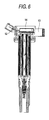
- the igniter 10 of Fig. 5 has the components packaged internally on one face or both faces of a single plane or a single layer of the substrate, whereby the igniter 10 has a large current portion and a small current portion of the circuit placed proximately on the internal wiring substrate.
- the mounting area is defined in three dimensions by the three dimensional wiring and arrangement of internal mounting substrate or the lead frame to make the effective use of the mounting space, whereby the igniter is saved in space. Further, each internal wiring substrate is divided into the large current circuit and the small current circuit, thereby making it possible to suppress an interference due to electromagnetic induction when the igniter is in operation, and design the igniter with the heat resistance.
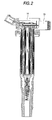
- the igniter that is molded with the ignites case 8 as the outer packaging is placed in an igniter mounting space within the ignition device case, as shown in Fig. 2. Since the external connection terminal 2 is already formed integrally with the igniter case 8, there is no need for the connector 1 as a separate part and the step of welding the igniter and the connector, resulting in the smaller number of parts and the reduced number of steps.
- the heat sink for heat radiation 4 is disposed within the igniter, and the driving element 6 consisting of a Darlington transistor for making switching drive to shut off or pass the primary current is disposed on its surface.
- the internal wiring substrate 5 is wired and arranged three dimensionally, and divided into the large current portion and the small current portion. Therefore, when the igniter is operated, it is possible to suppress an electromagnetic induction caused due to interference between adjacent patterns. The heat generated from heating parts when the igniter is operated is prevented from being passed, because the internal wiring substrate 5 is wired and arranged three dimensionally. Hence, the igniter is designed with some margin in view of the heat resistance of the parts themselves.
- the connector and the external connection terminal 2 of the igniter are integrated with the outer package of the igniter, and the igniter itself is contained within the igniter case 8.
- the number of parts and the number of assembling steps are reduced, and the assembling steps are simplified to the ignition device for internal combustion engine is supplied cheaply.
- the stress due to thermal expansion or contraction of the filling epoxy resin 14 is relieved on the igniter, thereby solving the first problem.
- the bonding points are required by the number of external terminals, with the lower reliability in proportion to the number of bonding points or the number of welding points.
Landscapes
- Engineering & Computer Science (AREA)
- Chemical & Material Sciences (AREA)
- Combustion & Propulsion (AREA)
- Mechanical Engineering (AREA)
- General Engineering & Computer Science (AREA)
- Ignition Installations For Internal Combustion Engines (AREA)
Applications Claiming Priority (2)
| Application Number | Priority Date | Filing Date | Title |
|---|---|---|---|
| JP2002111001 | 2002-04-12 | ||
| JP2002111001A JP2003309028A (ja) | 2002-04-12 | 2002-04-12 | 内燃機関用点火装置 |
Publications (3)
| Publication Number | Publication Date |
|---|---|
| EP1353066A2 true EP1353066A2 (de) | 2003-10-15 |
| EP1353066A3 EP1353066A3 (de) | 2004-06-16 |
| EP1353066B1 EP1353066B1 (de) | 2009-10-14 |
Family
ID=28449992
Family Applications (1)
| Application Number | Title | Priority Date | Filing Date |
|---|---|---|---|
| EP03002463A Expired - Lifetime EP1353066B1 (de) | 2002-04-12 | 2003-02-05 | Zündvorrichtung für einen Verbrennungsmotor |
Country Status (5)
| Country | Link |
|---|---|
| US (1) | US6851417B2 (de) |
| EP (1) | EP1353066B1 (de) |
| JP (1) | JP2003309028A (de) |
| CN (1) | CN1451862A (de) |
| DE (1) | DE60329647D1 (de) |
Cited By (1)
| Publication number | Priority date | Publication date | Assignee | Title |
|---|---|---|---|---|
| WO2012022575A1 (de) * | 2010-08-20 | 2012-02-23 | Robert Bosch Gmbh | Zündvorrichtung mit verbessertem wärmeverhalten |
Families Citing this family (11)
| Publication number | Priority date | Publication date | Assignee | Title |
|---|---|---|---|---|
| DE102005036445A1 (de) * | 2005-08-03 | 2007-02-15 | Robert Bosch Gmbh | Zündspule für eine Brennkraftmaschine |
| JP4954724B2 (ja) * | 2007-01-17 | 2012-06-20 | ダイヤモンド電機株式会社 | イグナイタ |
| JP2008202453A (ja) * | 2007-02-19 | 2008-09-04 | Denso Corp | 点火コイル用のイグナイタ |
| JP2008248782A (ja) * | 2007-03-30 | 2008-10-16 | Diamond Electric Mfg Co Ltd | イグナイタ |
| JP5084453B2 (ja) * | 2007-11-02 | 2012-11-28 | ダイヤモンド電機株式会社 | 内燃機関用点火コイル |
| DE102010062349A1 (de) * | 2010-12-02 | 2012-06-06 | Robert Bosch Gmbh | Zündspule mit integrierter Elektronik |
| US9341157B2 (en) * | 2012-12-17 | 2016-05-17 | Jake Petrosian | Catalytic fuel igniter |
| JP6409484B2 (ja) * | 2014-10-10 | 2018-10-24 | 株式会社デンソー | 内燃機関用点火コイル |
| WO2019220483A1 (ja) * | 2018-05-14 | 2019-11-21 | 三菱電機株式会社 | 内燃機関の点火コイル装置 |
| JP7232027B2 (ja) * | 2018-12-04 | 2023-03-02 | ダイヤゼブラ電機株式会社 | イグナイタ組立体およびイグナイタユニット |
| JP7388912B2 (ja) | 2019-12-23 | 2023-11-29 | ダイヤゼブラ電機株式会社 | イグナイタ |
Family Cites Families (12)
| Publication number | Priority date | Publication date | Assignee | Title |
|---|---|---|---|---|
| US5315982A (en) * | 1990-05-12 | 1994-05-31 | Combustion Electromagnetics, Inc. | High efficiency, high output, compact CD ignition coil |
| JPH0422762A (ja) * | 1990-05-16 | 1992-01-27 | Mitsubishi Electric Corp | イグナイタ |
| JPH0729746A (ja) * | 1993-07-09 | 1995-01-31 | Mitsubishi Electric Corp | 内燃機関用点火コイル装置 |
| US5558074A (en) * | 1994-07-28 | 1996-09-24 | Hitachi, Ltd. | Ignition device for internal-combustion engine |
| JP3550631B2 (ja) * | 1996-03-22 | 2004-08-04 | 株式会社デンソー | 点火コイルおよびその製造方法 |
| DE69812350T2 (de) * | 1997-05-23 | 2003-11-20 | Hitachi Car Engineering Co., Ltd. | Zündspulenanordnung für einen motor und motor mit einer kopfhaube aus plastik |
| JP3756691B2 (ja) * | 1999-03-18 | 2006-03-15 | 株式会社日立製作所 | 内燃機関用の樹脂封止形電子装置 |
| JP2000294692A (ja) * | 1999-04-06 | 2000-10-20 | Hitachi Ltd | 樹脂封止型電子装置及びその製造方法並びにそれを使用した内燃機関用点火コイル装置 |
| JP3866880B2 (ja) * | 1999-06-28 | 2007-01-10 | 株式会社日立製作所 | 樹脂封止型電子装置 |
| DE19933335C2 (de) * | 1999-07-16 | 2002-11-14 | Volkswagen Ag | Elektronisches Zündsystem für Brennkraftmaschinen |
| JP3513063B2 (ja) * | 1999-12-01 | 2004-03-31 | 株式会社日立製作所 | 内燃機関用点火装置 |
| DE20020737U1 (de) * | 2000-12-07 | 2002-04-18 | Robert Bosch Gmbh, 70469 Stuttgart | Zündspule für Brennkraftmaschinen |
-
2002
- 2002-04-12 JP JP2002111001A patent/JP2003309028A/ja active Pending
-
2003
- 2003-02-05 DE DE60329647T patent/DE60329647D1/de not_active Expired - Lifetime
- 2003-02-05 EP EP03002463A patent/EP1353066B1/de not_active Expired - Lifetime
- 2003-02-06 US US10/359,103 patent/US6851417B2/en not_active Expired - Lifetime
- 2003-02-13 CN CN03104177A patent/CN1451862A/zh active Pending
Cited By (1)
| Publication number | Priority date | Publication date | Assignee | Title |
|---|---|---|---|---|
| WO2012022575A1 (de) * | 2010-08-20 | 2012-02-23 | Robert Bosch Gmbh | Zündvorrichtung mit verbessertem wärmeverhalten |
Also Published As
| Publication number | Publication date |
|---|---|
| JP2003309028A (ja) | 2003-10-31 |
| CN1451862A (zh) | 2003-10-29 |
| DE60329647D1 (de) | 2009-11-26 |
| US6851417B2 (en) | 2005-02-08 |
| EP1353066A3 (de) | 2004-06-16 |
| EP1353066B1 (de) | 2009-10-14 |
| US20030192519A1 (en) | 2003-10-16 |
Similar Documents
| Publication | Publication Date | Title |
|---|---|---|
| EP1995439B1 (de) | Motorsteuerungseinheit | |
| EP1043771B1 (de) | Verfahren zur Herstellung einer Harzvergossenen elektronischen Anordnung | |
| EP0633609B1 (de) | Zusammengesetzte Leiterplatte, Halbleiterleistungsmodul mit dieser zusammengesetzten Leiterplatte und Herstellungsmethode dafür | |
| US6851417B2 (en) | Ignition device for internal combustion engine | |
| JP2001153017A (ja) | 内燃機関用点火装置 | |
| EP1065916B1 (de) | Harzverkapselte elektronische Vorrichtung | |
| CN102754205A (zh) | 电源模块及其制造方法 | |
| US7528469B2 (en) | Semiconductor equipment having multiple semiconductor devices and multiple lead frames | |
| JP2010245188A (ja) | 回路モジュール、その放熱構造、その製造方法 | |
| JP4270086B2 (ja) | 電子制御装置 | |
| US20080128920A1 (en) | Resin-sealed electronic device and method of manufacturing the same | |
| JP2004207432A (ja) | パワーモジュール | |
| US5467758A (en) | Electronic distributing type ignition device | |
| JP3886736B2 (ja) | 内燃機関用点火装置及びそれに用いる電子部品を内装したパッケージ | |
| US6758200B2 (en) | Ignition coil driver chip on printed circuit board for plughole coil housing | |
| US8174097B2 (en) | Electric sub-assembly | |
| CN103311231B (zh) | 半导体器件及其制造方法 | |
| JP3834559B2 (ja) | 内燃機関用点火コイルの作製方法および内燃機関用点火コイル | |
| JP2002260936A (ja) | 内燃機関の点火回路モジュール及び点火コイル装置 | |
| JPH05110268A (ja) | 封止型実装印刷配線板 | |
| JP3924968B2 (ja) | イグナイタ | |
| JP3955704B2 (ja) | 電気接続箱 | |
| JP3475770B2 (ja) | イグナイタ | |
| JP2005299608A (ja) | イグナイタ | |
| JP2005347521A (ja) | イグナイタ |
Legal Events
| Date | Code | Title | Description |
|---|---|---|---|
| PUAI | Public reference made under article 153(3) epc to a published international application that has entered the european phase |
Free format text: ORIGINAL CODE: 0009012 |
|
| AK | Designated contracting states |
Kind code of ref document: A2 Designated state(s): AT BE BG CH CY CZ DE DK EE ES FI FR GB GR HU IE IT LI LU MC NL PT SE SI SK TR |
|
| AX | Request for extension of the european patent |
Extension state: AL LT LV MK RO |
|
| PUAL | Search report despatched |
Free format text: ORIGINAL CODE: 0009013 |
|
| AK | Designated contracting states |
Kind code of ref document: A3 Designated state(s): AT BE BG CH CY CZ DE DK EE ES FI FR GB GR HU IE IT LI LU MC NL PT SE SI SK TR |
|
| AX | Request for extension of the european patent |
Extension state: AL LT LV MK RO |
|
| 17P | Request for examination filed |
Effective date: 20041122 |
|
| AKX | Designation fees paid |
Designated state(s): DE FR GB |
|
| 17Q | First examination report despatched |
Effective date: 20061107 |
|
| GRAP | Despatch of communication of intention to grant a patent |
Free format text: ORIGINAL CODE: EPIDOSNIGR1 |
|
| GRAS | Grant fee paid |
Free format text: ORIGINAL CODE: EPIDOSNIGR3 |
|
| GRAA | (expected) grant |
Free format text: ORIGINAL CODE: 0009210 |
|
| AK | Designated contracting states |
Kind code of ref document: B1 Designated state(s): DE FR GB |
|
| REG | Reference to a national code |
Ref country code: GB Ref legal event code: FG4D |
|
| REF | Corresponds to: |
Ref document number: 60329647 Country of ref document: DE Date of ref document: 20091126 Kind code of ref document: P |
|
| PLBE | No opposition filed within time limit |
Free format text: ORIGINAL CODE: 0009261 |
|
| STAA | Information on the status of an ep patent application or granted ep patent |
Free format text: STATUS: NO OPPOSITION FILED WITHIN TIME LIMIT |
|
| 26N | No opposition filed |
Effective date: 20100715 |
|
| PGFP | Annual fee paid to national office [announced via postgrant information from national office to epo] |
Ref country code: FR Payment date: 20120221 Year of fee payment: 10 |
|
| PGFP | Annual fee paid to national office [announced via postgrant information from national office to epo] |
Ref country code: DE Payment date: 20120131 Year of fee payment: 10 |
|
| PGFP | Annual fee paid to national office [announced via postgrant information from national office to epo] |
Ref country code: GB Payment date: 20120201 Year of fee payment: 10 |
|
| GBPC | Gb: european patent ceased through non-payment of renewal fee |
Effective date: 20130205 |
|
| REG | Reference to a national code |
Ref country code: FR Ref legal event code: ST Effective date: 20131031 |
|
| REG | Reference to a national code |
Ref country code: DE Ref legal event code: R119 Ref document number: 60329647 Country of ref document: DE Effective date: 20130903 |
|
| PG25 | Lapsed in a contracting state [announced via postgrant information from national office to epo] |
Ref country code: FR Free format text: LAPSE BECAUSE OF NON-PAYMENT OF DUE FEES Effective date: 20130228 Ref country code: GB Free format text: LAPSE BECAUSE OF NON-PAYMENT OF DUE FEES Effective date: 20130205 Ref country code: DE Free format text: LAPSE BECAUSE OF NON-PAYMENT OF DUE FEES Effective date: 20130903 |