EP1353066B1 - Zündvorrichtung für einen Verbrennungsmotor - Google Patents
Zündvorrichtung für einen Verbrennungsmotor Download PDFInfo
- Publication number
- EP1353066B1 EP1353066B1 EP03002463A EP03002463A EP1353066B1 EP 1353066 B1 EP1353066 B1 EP 1353066B1 EP 03002463 A EP03002463 A EP 03002463A EP 03002463 A EP03002463 A EP 03002463A EP 1353066 B1 EP1353066 B1 EP 1353066B1
- Authority
- EP
- European Patent Office
- Prior art keywords
- igniter
- ignition device
- case
- molding resin
- substrate
- Prior art date
- Legal status (The legal status is an assumption and is not a legal conclusion. Google has not performed a legal analysis and makes no representation as to the accuracy of the status listed.)
- Expired - Lifetime
Links
Images


Classifications
-
- F—MECHANICAL ENGINEERING; LIGHTING; HEATING; WEAPONS; BLASTING
- F02—COMBUSTION ENGINES; HOT-GAS OR COMBUSTION-PRODUCT ENGINE PLANTS
- F02P—IGNITION, OTHER THAN COMPRESSION IGNITION, FOR INTERNAL-COMBUSTION ENGINES; TESTING OF IGNITION TIMING IN COMPRESSION-IGNITION ENGINES
- F02P3/00—Other installations
- F02P3/02—Other installations having inductive energy storage, e.g. arrangements of induction coils
-
- H—ELECTRICITY
- H10—SEMICONDUCTOR DEVICES; ELECTRIC SOLID-STATE DEVICES NOT OTHERWISE PROVIDED FOR
- H10W—GENERIC PACKAGES, INTERCONNECTIONS, CONNECTORS OR OTHER CONSTRUCTIONAL DETAILS OF DEVICES COVERED BY CLASS H10
- H10W72/00—Interconnections or connectors in packages
- H10W72/50—Bond wires
- H10W72/531—Shapes of wire connectors
- H10W72/5363—Shapes of wire connectors the connected ends being wedge-shaped
Definitions
- the present invention relates to an igniter for controlling a primary current to be turned on or off, which is used with an ignition device for internal combustion engine, and more particularly to an ignition device for internal combustion engine in which an igniter and an ignition coil are integrated within an ignition device case.
- an ignition device for internal combustion engine in which an igniter and an ignition coil are equipped within the same ignition device case.
- the ignition device arranged for each ignition plug is spread.
- Fig. 5 shows the structure of an igniter for use with this ignition device
- Fig. 6 show a method of mounting the igniter on the ignition coil of the ignition device for internal combustion engine.
- the ignition coil and the igniter are indispensable for each other and employed as a set in the ignition device for internal combustion engine.
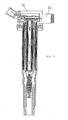
- the ignition device has a primary coil and a secondary coil buried in a plug hole provided in an engine main body, not shown, in which an igniter 10 is disposed directly above the coil portion and outside the plug hole, these being accommodated within an ignition device case.
- the igniter 10 is connected to a connector 1 having an external connection terminal 2 for supplying the power from a battery or the like, and an igniter metal terminal 9 connected to the external connection terminal 2.
- a cover 11 made of an elastic material such as resin is put on the igniter 10, and a filling epoxy resin is filled in the entity of the igniter 10 and cured to have the finished product.
- the igniter 10 When the igniter 10 is mounted on the ignition coil 13, first of all, the igniter 10 is fitted into the connector 1. Then, the igniter metal terminal 9 provided on the side face of the igniter 10 and the external connection terminal 2 provided in the connector 1 are joined by welding or the like.
- an igniter connector ASSY 12 having the connector 1 fitted is attached to the ignition coil 13. Thereafter, the upper part of the ignition coil 13 having the igniter 10 mounted is filled and sealed with the filling epoxy resin 14, whereby the igniter 10 is fixed.
- the igniter 10 of Fig. 5 has the components packaged internally on one face or both faces of a single plane or a single layer of the substrate, whereby the igniter 10 has a large current portion and a small current portion of the circuit placed proximately on the internal wiring substrate.
- the igniter 10 has the following problems.
- a first problem is that the connection with the external connection terminal 2 must be made using the connector 1 that is prepared as a separate part, and before the igniter 10 itself is placed in the ignition coil 13, the electrical or mechanical connection between the igniter 10 and the connector 1 by welding or the like is required, increasing in the number of parts, degrading the operability of welding, or increasing the number of steps needed for welding.
- a number of bonding points are required corresponding to the number of external terminals, and if the number of bonding or welding points is increased, there occurs a problem with non-contactness at the connection, with the reliability lower in proportion to an increase in the number of contact portions.
- a second problem is that a mounting portion of the igniter 10 in the ignition coil 13 is filled and sealed with the filling epoxy resin 14 to fix the igniter 10 joined with the connector 1, but the igniter 10 itself is of the structure that is only molded with the molding resin 7, whereby the cover 11 is needed as a separate part to relieve a stress due to thermal expansion or contraction of the filling epoxy resin 14.
- the cover 11 is needed as a separate part to relieve a stress due to thermal expansion or contraction of the filling epoxy resin 14.
- a third problem is that when all the components are arranged on a single plane of the internal wiring substrate or lead frame to give the added value to the igniter, it is necessary to take a large space for the internal wiring substrate, and the igniter 10 is limited in saving the space.
- the components are arranged on the single or double faces of the internal wiring substrate, whereby the large current portion and the small current portion are placed proximately in the circuit of the internal wiring substrate, causing a current produced during the operation of the igniter 10 to affect adjacent conductive patterns, and causing the noise of the igniter 10 due to an interference of electromagnetic induction, resulting in an adverse influence on the primary current shut-off control.
- the igniter 10 is driven, heat produced from the internal packaged components will easily affect the components on the single plane.
- WO 01/06117 discloses an ignition device according to the preamble of claim 1.
- This invention is achieved in the light of the above-mentioned problems, and it is an object of the invention to provide an igniter in which the number of parts is reduced, the number of assembling steps is reduced, and the thermal stress is lowered.
- the present invention provides the following constitution.
- the external connection terminal connector as a separate part that mounts the igniter is abolished, and the external connection terminal is integrated with the igniter itself.
- the igniter has the electronic components mounted on the internal wiring substrate made of ceramic, and is accommodated, together with the IGBT and the heat sink for heat radiation, within the plastic case.
- the conduction between the electronic components within the igniter and the external connection terminal can be directly made by wire bonding with the external connection terminal.
- the outer package of the igniter is the plastic case, or the rubber based cushioning material is coated on the surface of the igniter.
- the internal parts of the igniter are wired and arranged three dimensionally, and the igniter is divided into the large current circuit portion and the small current circuit portion.
- the three dimensional wiring and arrangement of the circuit may be the lead frame.
- an ignition device for internal combustion engine comprising an igniter case having a primary input terminal, in which an igniter is disposed, and an ignition coil under the igniter case, characterized in that the igniter arranged in the igniter case and the primary input terminal are connected by wire bonding and thereby integrally molded.
- the ignition device for internal combustion engine is characterized in that a molding resin is filled in the igniter case, and the igniter case is made of plastic capable of absorbing an expansion or contraction stress of the molding resin.
- the ignition device for internal combustion engine is characterized in that a molding resin is filled in the igniter case, and a rubber based cushioning material is coated on the surface of the molding resin.
- the ignition device for internal combustion engine is characterized in that a molding resin is filled in the igniter case, and after the igniter case is disposed at a predetermined position, a filling epoxy resin is poured into an ignition device case and cured, wherein a rubber based cushioning material is mixed into at least one of the molding resin or the filling epoxy resin.
- an ignition device for internal combustion engine comprising an igniter case having a primary input terminal, in which an igniter is disposed, and an ignition coil under the igniter case, characterized in that the igniter is disposed in the igniter case and consists of a driving element on amounting substrate or a lead frame, in which the mounting substrate or lead frame and the primary input terminal are connected by three dimensional wiring. Further, the ignition device for internal combustion engine is characterized in that an internal wiring substrate forming the igniter is divided into a large current substrate and a small current substrate.
- the connector as the separate part and the step of welding the igniter with the connector can be omitted.
- the stress due to thermal expansionor contraction of the filling epoxy resin to fix the igniter within the ignition device can be relieved only by the plastic case that is the outer package of the igniter, without the use of the cover as the separate part.
- the stress due to thermal expansion or contraction of the filling epoxy resin to fix the igniter within the ignition device can be relieved only by the plastic case that is the outer package of the igniter, without the use of the cover as the separate part.
- the mounting area is defined in three dimensions by the three dimensional wiring and arrangement of internal mounting substrate or the lead frame to make the effective use of the mounting space, whereby the igniter is saved in space. Further, each internal wiring substrate is divided into the large current circuit and the small current circuit, thereby making it possible to suppress an interference due to electromagnetic induction when the igniter is in operation, and design the igniter with the heat resistance.
- an igniter is not a package product such as a general-purpose power transistor or IGBT, but a component before molding in which a driving element 6 is arranged on an internal wiring substrate.
- an ignition device of this invention is composed of the igniter and an ignition coil 13, both of which are accommodated within the same ignition device case, in which the igniter is contained in an igniter case and filled with a molding resin.
- the igniter comprises an internal wiring substrate 5 made of ceramics and formed of alumina, which has a driving control IC.
- the internal wiring substrate 5 has a circuit pattern printed and the electronic components mounted to provide the additional functions, and bonded on a heat sink for heat radiation 4 by adhesives.
- the driving element 6 consisting of a Darlington transistor for making switching drive to turn on or off the primary current is disposed.
- the driving element 6 may consist of IGBT.
- the internal wiring substrate 5 and these components making up the igniter, such as the driving element 6 and the heat sink for heat radiation 4 are accommodated within the igniter case 8 formed of plastic such as PPO, PPT, PBT and PET.
- the igniter case 8 has the connector 1 for connecting to the external connection terminal 2, the ignites and the external connection terminal 2 being integrally molded.
- the igniter components accommodated within the igniter case 8 and the external connection terminal 2 are electrically connected by a bonding wire 3, and the igniter is molded by a molding resin 7 with the igniter case 8 as the outer packaging after wire bonding.
- the igniter that is molded with the ignites case 8 as the outer packaging is placed in an igniter mounting space within the ignition device case, as shown in Fig. 2 . Since the external connection terminal 2 is already formed integrally with the igniter case 8, there is no need for the connector 1 as a separate part and the step of welding the igniter and the connector, resulting in the smaller number of parts and the reduced number of steps.
- the igniter is electrically connected with the ignition coil 13, then filled with the filling epoxy resin 14 and fixed, as shown in Fig. 2 .
- the thermal expansion or contraction coefficient of the filling epoxy resin 14 is higher than that of other parts, but because the stress developed due to the thermal expansion or contraction of the filling epoxy resin 14 is relieved by the igniter case 8, the stress applied on the igniter itself is reduced without the use of the cover 11 for igniter that is conventionally employed as the separate part.
- FIG. 3 A second embodiment of this invention will be described below.
- the structure of a main portion is the same as described in the first embodiment, and the different points from the first embodiment will be only described.
- the inside of the igniter case 8 is molded by the molding resin 7, and a rubber based cushioning material is coated on a surface layer of the igniter.
- the igniter is electrically connected with the ignition coil 13, then filled with the filling epoxy resin 14 and fixed, as shown in Fig. 2 .
- the thermal expansion or contraction coefficient of the filling epoxy resin 14 is higher than that of other parts, but because the stress developed due to the thermal expansion or contraction of the filling epoxy resin 14 is relieved by the rubber based cushioning material 15 coated on the surface layer of the igniter, igniter case 8, the stress applied on the igniter itself is reduced without the use of special cover for covering the entire igniter.
- the rubber based cushioning material 15 is not coated on the surface of the filling epoxy resin 14 but may be mixed on at least one of the filling epoxy resin 14 or the molding resin 7 to obtain the cushioning action, whereby the rubber based cushioning material 15 may be mixed into at least one of those resins.
- the igniter of this invention comprises the internal wiring substrate 5 made of ceramics and formed of alumina, which has the driving control IC.
- the internal wiring substrate 5 has a circuit pattern printed and the electronic components mounted to provide the additional functions, and is divided into a large current circuit portion and a small current circuit portion, in which the wiring substrate is wired and arranged three-dimensionally in a form in which those circuit portions are placed one on another and electrically connected.
- the three dimensional arrangement and wiring of the circuit may be made using a lead frame.
- the heat sink for heat radiation 4 is disposed within the igniter, and the driving element 6 consisting of a Darlington transistor for making switching drive to shut off or pass the primary current is disposed on its surface.
- the igniter has a marginal space because the internal wiring substrate 5 is wired and arranged three dimensionally, when a number of parts are arranged to provide the additional functions, and thereby the space saving of the igniter is enabled.
- the internal wiring substrate 5 is wired and arranged three dimensionally, and divided into the large current portion and the small current portion. Therefore, when the igniter is operated, it is possible to suppress an electromagnetic induction caused due to interference between adjacent patterns. The heat generated from heating parts when the igniter is operated is prevented from being passed, because the internal wiring substrate 5 is wired and arranged three dimensionally. Hence, the igniter is designed with some margin in view of the heat resistance of the parts themselves.
- the connector and the external connection terminal 2 of the igniter are integrated with the outer package of the igniter, and the igniter itself is contained within the igniter case 8.
- the number of parts and the number of assembling steps are reduced, and the assembling steps are simplified to the ignition device for internal combustion engine is supplied cheaply.
- the stress due to thermal expansion or contraction of the filling epoxy resin 14 is relieved on the igniter, thereby solving the first problem.
- the bonding points are required by the number of external terminals, with the lower reliability in proportion to the number of bonding points or the number of welding points.
- the number of bonding points is reduced in view of enhancing the reliability of the semiconductor assembly, and both the connector and the external connection terminal, which are problematical with the conventional structure, are joined using the terminal with high heat capacity, thereby substantially eliminating the frequent replacement of the welded terminal.
- the stress due to thermal expansion or contraction of the filling epoxy resin 14 is relieved on the igniter by the rubber based cushioning material 15, thereby solving the second problem.
- the internal mounting substrate 5 or the lead frame is wired and arranged in three dimensions to make the effective use of the mounting space, whereby the igniter is saved in space. Further, it is possible to suppress an interference due to electromagnetic induction when the igniter is in operation, and design the igniter with the heat resistance, thereby solving the third problem.
Landscapes
- Engineering & Computer Science (AREA)
- Chemical & Material Sciences (AREA)
- Combustion & Propulsion (AREA)
- Mechanical Engineering (AREA)
- General Engineering & Computer Science (AREA)
- Ignition Installations For Internal Combustion Engines (AREA)
Claims (5)
- Zündvorrichtung für einen Motor mit innerer Verbrennung, mit
einem Zündergehäuse (8), das einen primären Eingangsanschluss (2) aufweist,
einem Zünder, der in dem Zündergehäuse (8) angeordnet ist, und
einer Zündspule (13), die unter dem Zündergehäuse (8) angeordnet ist,
dadurch gekennzeichnet, dass
der Zünder und der primäre Eingangsanschluss (2) durch Drahtbonden (3) verbunden und integral geformt sind,
ein internes Verdrahtungssubstrat (5), das den Zünder ausbildet, in ein Substrat für einen großen Strom und ein Substrat für einen kleinen Strom geteilt ist, und
das Substrat für einen großen Strom und das Substrat für einen kleinen Strom auf eine Weise dreidimensional angeordnet sind, so dass sie übereinander platziert und elektrisch verbunden sind. - Zündvorrichtung nach Anspruch 1, bei der
ein Pressharz in das Zündergehäuse (8) gefüllt ist, und
das Zündergehäuse (8) aus einem Kunststoff hergestellt ist, der in der Lage ist, eine Expansions- oder Kontraktionsspannung des Pressharzes zu absorbieren. - Zündvorrichtung nach Anspruch 1 oder 2, bei der
ein Pressharz in das Zündergehäuse (8) gefüllt ist, und
die Oberfläche des Pressharzes mit einem gummibasierten Puffermaterial beschichtet ist. - Zündvorrichtung nach einem der Ansprüche 1 bis 3, bei der
ein Pressharz in das Zündergehäuse (8) gefüllt ist,
nachdem das Zündergehäuse (8) an einer vorbestimmten Position angeordnet ist, ein Füllepoxidharz in ein Zündvorrichtungsgehäuse gegossen und ausgehärtet wird, und
ein gummibasiertes Puffermaterial in mindestens entweder das Pressharz oder das Füllepoxidharz gemischt ist. - Zündvorrichtung nach einem der Ansprüche 1 bis 4, bei der
der Zünder ein Steuerelement (6) an einem Befestigungssubstrat oder einem Leitungsrahmen aufweist, wobei das Befestigungssubstrat oder der Leitungsrahmen und der primäre Eingangsanschluss (2) durch eine dreidimensionale Verdrahtung verbunden sind.
Applications Claiming Priority (2)
| Application Number | Priority Date | Filing Date | Title |
|---|---|---|---|
| JP2002111001 | 2002-04-12 | ||
| JP2002111001A JP2003309028A (ja) | 2002-04-12 | 2002-04-12 | 内燃機関用点火装置 |
Publications (3)
| Publication Number | Publication Date |
|---|---|
| EP1353066A2 EP1353066A2 (de) | 2003-10-15 |
| EP1353066A3 EP1353066A3 (de) | 2004-06-16 |
| EP1353066B1 true EP1353066B1 (de) | 2009-10-14 |
Family
ID=28449992
Family Applications (1)
| Application Number | Title | Priority Date | Filing Date |
|---|---|---|---|
| EP03002463A Expired - Lifetime EP1353066B1 (de) | 2002-04-12 | 2003-02-05 | Zündvorrichtung für einen Verbrennungsmotor |
Country Status (5)
| Country | Link |
|---|---|
| US (1) | US6851417B2 (de) |
| EP (1) | EP1353066B1 (de) |
| JP (1) | JP2003309028A (de) |
| CN (1) | CN1451862A (de) |
| DE (1) | DE60329647D1 (de) |
Families Citing this family (12)
| Publication number | Priority date | Publication date | Assignee | Title |
|---|---|---|---|---|
| DE102005036445A1 (de) * | 2005-08-03 | 2007-02-15 | Robert Bosch Gmbh | Zündspule für eine Brennkraftmaschine |
| JP4954724B2 (ja) * | 2007-01-17 | 2012-06-20 | ダイヤモンド電機株式会社 | イグナイタ |
| JP2008202453A (ja) * | 2007-02-19 | 2008-09-04 | Denso Corp | 点火コイル用のイグナイタ |
| JP2008248782A (ja) * | 2007-03-30 | 2008-10-16 | Diamond Electric Mfg Co Ltd | イグナイタ |
| JP5084453B2 (ja) * | 2007-11-02 | 2012-11-28 | ダイヤモンド電機株式会社 | 内燃機関用点火コイル |
| DE102010039587A1 (de) * | 2010-08-20 | 2012-02-23 | Robert Bosch Gmbh | Zündvorrichtung mit verbessertem Wärmeverhalten |
| DE102010062349A1 (de) * | 2010-12-02 | 2012-06-06 | Robert Bosch Gmbh | Zündspule mit integrierter Elektronik |
| US9341157B2 (en) * | 2012-12-17 | 2016-05-17 | Jake Petrosian | Catalytic fuel igniter |
| JP6409484B2 (ja) * | 2014-10-10 | 2018-10-24 | 株式会社デンソー | 内燃機関用点火コイル |
| WO2019220483A1 (ja) * | 2018-05-14 | 2019-11-21 | 三菱電機株式会社 | 内燃機関の点火コイル装置 |
| JP7232027B2 (ja) * | 2018-12-04 | 2023-03-02 | ダイヤゼブラ電機株式会社 | イグナイタ組立体およびイグナイタユニット |
| JP7388912B2 (ja) | 2019-12-23 | 2023-11-29 | ダイヤゼブラ電機株式会社 | イグナイタ |
Citations (2)
| Publication number | Priority date | Publication date | Assignee | Title |
|---|---|---|---|---|
| EP1043771A2 (de) * | 1999-04-06 | 2000-10-11 | Hitachi, Ltd. | Harzvergossene elektronische Anordnung und Herstellungsverfahren dafür, und Zündspule für eine Brennkraftmaschine mit einer solchen Anordnung |
| US6257215B1 (en) * | 1999-03-18 | 2001-07-10 | Hitachi, Ltd. | Resin-sealed electronic apparatus for use in internal combustion engines |
Family Cites Families (10)
| Publication number | Priority date | Publication date | Assignee | Title |
|---|---|---|---|---|
| US5315982A (en) * | 1990-05-12 | 1994-05-31 | Combustion Electromagnetics, Inc. | High efficiency, high output, compact CD ignition coil |
| JPH0422762A (ja) * | 1990-05-16 | 1992-01-27 | Mitsubishi Electric Corp | イグナイタ |
| JPH0729746A (ja) * | 1993-07-09 | 1995-01-31 | Mitsubishi Electric Corp | 内燃機関用点火コイル装置 |
| US5558074A (en) * | 1994-07-28 | 1996-09-24 | Hitachi, Ltd. | Ignition device for internal-combustion engine |
| JP3550631B2 (ja) * | 1996-03-22 | 2004-08-04 | 株式会社デンソー | 点火コイルおよびその製造方法 |
| DE69812350T2 (de) * | 1997-05-23 | 2003-11-20 | Hitachi Car Engineering Co., Ltd. | Zündspulenanordnung für einen motor und motor mit einer kopfhaube aus plastik |
| JP3866880B2 (ja) * | 1999-06-28 | 2007-01-10 | 株式会社日立製作所 | 樹脂封止型電子装置 |
| DE19933335C2 (de) * | 1999-07-16 | 2002-11-14 | Volkswagen Ag | Elektronisches Zündsystem für Brennkraftmaschinen |
| JP3513063B2 (ja) * | 1999-12-01 | 2004-03-31 | 株式会社日立製作所 | 内燃機関用点火装置 |
| DE20020737U1 (de) * | 2000-12-07 | 2002-04-18 | Robert Bosch Gmbh, 70469 Stuttgart | Zündspule für Brennkraftmaschinen |
-
2002
- 2002-04-12 JP JP2002111001A patent/JP2003309028A/ja active Pending
-
2003
- 2003-02-05 DE DE60329647T patent/DE60329647D1/de not_active Expired - Lifetime
- 2003-02-05 EP EP03002463A patent/EP1353066B1/de not_active Expired - Lifetime
- 2003-02-06 US US10/359,103 patent/US6851417B2/en not_active Expired - Lifetime
- 2003-02-13 CN CN03104177A patent/CN1451862A/zh active Pending
Patent Citations (2)
| Publication number | Priority date | Publication date | Assignee | Title |
|---|---|---|---|---|
| US6257215B1 (en) * | 1999-03-18 | 2001-07-10 | Hitachi, Ltd. | Resin-sealed electronic apparatus for use in internal combustion engines |
| EP1043771A2 (de) * | 1999-04-06 | 2000-10-11 | Hitachi, Ltd. | Harzvergossene elektronische Anordnung und Herstellungsverfahren dafür, und Zündspule für eine Brennkraftmaschine mit einer solchen Anordnung |
Also Published As
| Publication number | Publication date |
|---|---|
| JP2003309028A (ja) | 2003-10-31 |
| CN1451862A (zh) | 2003-10-29 |
| DE60329647D1 (de) | 2009-11-26 |
| US6851417B2 (en) | 2005-02-08 |
| EP1353066A3 (de) | 2004-06-16 |
| EP1353066A2 (de) | 2003-10-15 |
| US20030192519A1 (en) | 2003-10-16 |
Similar Documents
| Publication | Publication Date | Title |
|---|---|---|
| EP1995439B1 (de) | Motorsteuerungseinheit | |
| EP0633609B1 (de) | Zusammengesetzte Leiterplatte, Halbleiterleistungsmodul mit dieser zusammengesetzten Leiterplatte und Herstellungsmethode dafür | |
| EP1353066B1 (de) | Zündvorrichtung für einen Verbrennungsmotor | |
| JP3910497B2 (ja) | 電力回路部の防水方法及び電力回路部をもつパワーモジュール | |
| EP1043771B1 (de) | Verfahren zur Herstellung einer Harzvergossenen elektronischen Anordnung | |
| US5747875A (en) | Semiconductor power module with high speed operation and miniaturization | |
| JP2001210784A (ja) | 可撓性パワー装置 | |
| JP2001153017A (ja) | 内燃機関用点火装置 | |
| EP1065916B1 (de) | Harzverkapselte elektronische Vorrichtung | |
| US7528469B2 (en) | Semiconductor equipment having multiple semiconductor devices and multiple lead frames | |
| JP2010245188A (ja) | 回路モジュール、その放熱構造、その製造方法 | |
| JP4270086B2 (ja) | 電子制御装置 | |
| US20080128920A1 (en) | Resin-sealed electronic device and method of manufacturing the same | |
| JP2004207432A (ja) | パワーモジュール | |
| US5467758A (en) | Electronic distributing type ignition device | |
| US20050146410A1 (en) | Ignition coil | |
| US6758200B2 (en) | Ignition coil driver chip on printed circuit board for plughole coil housing | |
| US8174097B2 (en) | Electric sub-assembly | |
| JP3886736B2 (ja) | 内燃機関用点火装置及びそれに用いる電子部品を内装したパッケージ | |
| JP3169578B2 (ja) | 電子部品用基板 | |
| US8791563B2 (en) | Semiconductor device and manufacturing method thereof | |
| JP3834559B2 (ja) | 内燃機関用点火コイルの作製方法および内燃機関用点火コイル | |
| JPH09246433A (ja) | モジュールの放熱構造 | |
| JP2002260936A (ja) | 内燃機関の点火回路モジュール及び点火コイル装置 | |
| JP3955704B2 (ja) | 電気接続箱 |
Legal Events
| Date | Code | Title | Description |
|---|---|---|---|
| PUAI | Public reference made under article 153(3) epc to a published international application that has entered the european phase |
Free format text: ORIGINAL CODE: 0009012 |
|
| AK | Designated contracting states |
Kind code of ref document: A2 Designated state(s): AT BE BG CH CY CZ DE DK EE ES FI FR GB GR HU IE IT LI LU MC NL PT SE SI SK TR |
|
| AX | Request for extension of the european patent |
Extension state: AL LT LV MK RO |
|
| PUAL | Search report despatched |
Free format text: ORIGINAL CODE: 0009013 |
|
| AK | Designated contracting states |
Kind code of ref document: A3 Designated state(s): AT BE BG CH CY CZ DE DK EE ES FI FR GB GR HU IE IT LI LU MC NL PT SE SI SK TR |
|
| AX | Request for extension of the european patent |
Extension state: AL LT LV MK RO |
|
| 17P | Request for examination filed |
Effective date: 20041122 |
|
| AKX | Designation fees paid |
Designated state(s): DE FR GB |
|
| 17Q | First examination report despatched |
Effective date: 20061107 |
|
| GRAP | Despatch of communication of intention to grant a patent |
Free format text: ORIGINAL CODE: EPIDOSNIGR1 |
|
| GRAS | Grant fee paid |
Free format text: ORIGINAL CODE: EPIDOSNIGR3 |
|
| GRAA | (expected) grant |
Free format text: ORIGINAL CODE: 0009210 |
|
| AK | Designated contracting states |
Kind code of ref document: B1 Designated state(s): DE FR GB |
|
| REG | Reference to a national code |
Ref country code: GB Ref legal event code: FG4D |
|
| REF | Corresponds to: |
Ref document number: 60329647 Country of ref document: DE Date of ref document: 20091126 Kind code of ref document: P |
|
| PLBE | No opposition filed within time limit |
Free format text: ORIGINAL CODE: 0009261 |
|
| STAA | Information on the status of an ep patent application or granted ep patent |
Free format text: STATUS: NO OPPOSITION FILED WITHIN TIME LIMIT |
|
| 26N | No opposition filed |
Effective date: 20100715 |
|
| PGFP | Annual fee paid to national office [announced via postgrant information from national office to epo] |
Ref country code: FR Payment date: 20120221 Year of fee payment: 10 |
|
| PGFP | Annual fee paid to national office [announced via postgrant information from national office to epo] |
Ref country code: DE Payment date: 20120131 Year of fee payment: 10 |
|
| PGFP | Annual fee paid to national office [announced via postgrant information from national office to epo] |
Ref country code: GB Payment date: 20120201 Year of fee payment: 10 |
|
| GBPC | Gb: european patent ceased through non-payment of renewal fee |
Effective date: 20130205 |
|
| REG | Reference to a national code |
Ref country code: FR Ref legal event code: ST Effective date: 20131031 |
|
| REG | Reference to a national code |
Ref country code: DE Ref legal event code: R119 Ref document number: 60329647 Country of ref document: DE Effective date: 20130903 |
|
| PG25 | Lapsed in a contracting state [announced via postgrant information from national office to epo] |
Ref country code: FR Free format text: LAPSE BECAUSE OF NON-PAYMENT OF DUE FEES Effective date: 20130228 Ref country code: GB Free format text: LAPSE BECAUSE OF NON-PAYMENT OF DUE FEES Effective date: 20130205 Ref country code: DE Free format text: LAPSE BECAUSE OF NON-PAYMENT OF DUE FEES Effective date: 20130903 |