EP1353093A1 - Actuateur linéaire - Google Patents
Actuateur linéaire Download PDFInfo
- Publication number
- EP1353093A1 EP1353093A1 EP03008255A EP03008255A EP1353093A1 EP 1353093 A1 EP1353093 A1 EP 1353093A1 EP 03008255 A EP03008255 A EP 03008255A EP 03008255 A EP03008255 A EP 03008255A EP 1353093 A1 EP1353093 A1 EP 1353093A1
- Authority
- EP
- European Patent Office
- Prior art keywords
- drive device
- linear drive
- profile element
- guide body
- base section
- Prior art date
- Legal status (The legal status is an assumption and is not a legal conclusion. Google has not performed a legal analysis and makes no representation as to the accuracy of the status listed.)
- Withdrawn
Links
- 230000000873 masking effect Effects 0.000 description 7
- 230000003134 recirculating effect Effects 0.000 description 3
- 230000004308 accommodation Effects 0.000 description 1
- 238000004873 anchoring Methods 0.000 description 1
Images


Classifications
-
- F—MECHANICAL ENGINEERING; LIGHTING; HEATING; WEAPONS; BLASTING
- F16—ENGINEERING ELEMENTS AND UNITS; GENERAL MEASURES FOR PRODUCING AND MAINTAINING EFFECTIVE FUNCTIONING OF MACHINES OR INSTALLATIONS; THERMAL INSULATION IN GENERAL
- F16C—SHAFTS; FLEXIBLE SHAFTS; ELEMENTS OR CRANKSHAFT MECHANISMS; ROTARY BODIES OTHER THAN GEARING ELEMENTS; BEARINGS
- F16C29/00—Bearings for parts moving only linearly
- F16C29/04—Ball or roller bearings
- F16C29/06—Ball or roller bearings in which the rolling bodies circulate partly without carrying load
- F16C29/063—Ball or roller bearings in which the rolling bodies circulate partly without carrying load with a bearing body, e.g. a carriage or part thereof, provided between the legs of a U-shaped guide rail or track
-
- B—PERFORMING OPERATIONS; TRANSPORTING
- B23—MACHINE TOOLS; METAL-WORKING NOT OTHERWISE PROVIDED FOR
- B23Q—DETAILS, COMPONENTS, OR ACCESSORIES FOR MACHINE TOOLS, e.g. ARRANGEMENTS FOR COPYING OR CONTROLLING; MACHINE TOOLS IN GENERAL CHARACTERISED BY THE CONSTRUCTION OF PARTICULAR DETAILS OR COMPONENTS; COMBINATIONS OR ASSOCIATIONS OF METAL-WORKING MACHINES, NOT DIRECTED TO A PARTICULAR RESULT
- B23Q1/00—Members which are comprised in the general build-up of a form of machine, particularly relatively large fixed members
- B23Q1/01—Frames, beds, pillars or like members; Arrangement of ways
-
- B—PERFORMING OPERATIONS; TRANSPORTING
- B23—MACHINE TOOLS; METAL-WORKING NOT OTHERWISE PROVIDED FOR
- B23Q—DETAILS, COMPONENTS, OR ACCESSORIES FOR MACHINE TOOLS, e.g. ARRANGEMENTS FOR COPYING OR CONTROLLING; MACHINE TOOLS IN GENERAL CHARACTERISED BY THE CONSTRUCTION OF PARTICULAR DETAILS OR COMPONENTS; COMBINATIONS OR ASSOCIATIONS OF METAL-WORKING MACHINES, NOT DIRECTED TO A PARTICULAR RESULT
- B23Q1/00—Members which are comprised in the general build-up of a form of machine, particularly relatively large fixed members
- B23Q1/25—Movable or adjustable work or tool supports
- B23Q1/44—Movable or adjustable work or tool supports using particular mechanisms
- B23Q1/56—Movable or adjustable work or tool supports using particular mechanisms with sliding pairs only, the sliding pairs being the first two elements of the mechanism
- B23Q1/58—Movable or adjustable work or tool supports using particular mechanisms with sliding pairs only, the sliding pairs being the first two elements of the mechanism a single sliding pair
-
- F—MECHANICAL ENGINEERING; LIGHTING; HEATING; WEAPONS; BLASTING
- F16—ENGINEERING ELEMENTS AND UNITS; GENERAL MEASURES FOR PRODUCING AND MAINTAINING EFFECTIVE FUNCTIONING OF MACHINES OR INSTALLATIONS; THERMAL INSULATION IN GENERAL
- F16C—SHAFTS; FLEXIBLE SHAFTS; ELEMENTS OR CRANKSHAFT MECHANISMS; ROTARY BODIES OTHER THAN GEARING ELEMENTS; BEARINGS
- F16C29/00—Bearings for parts moving only linearly
- F16C29/008—Systems with a plurality of bearings, e.g. four carriages supporting a slide on two parallel rails
-
- F—MECHANICAL ENGINEERING; LIGHTING; HEATING; WEAPONS; BLASTING
- F16—ENGINEERING ELEMENTS AND UNITS; GENERAL MEASURES FOR PRODUCING AND MAINTAINING EFFECTIVE FUNCTIONING OF MACHINES OR INSTALLATIONS; THERMAL INSULATION IN GENERAL
- F16C—SHAFTS; FLEXIBLE SHAFTS; ELEMENTS OR CRANKSHAFT MECHANISMS; ROTARY BODIES OTHER THAN GEARING ELEMENTS; BEARINGS
- F16C2322/00—Apparatus used in shaping articles
- F16C2322/39—General buildup of machine tools, e.g. spindles, slides, actuators
-
- F—MECHANICAL ENGINEERING; LIGHTING; HEATING; WEAPONS; BLASTING
- F16—ENGINEERING ELEMENTS AND UNITS; GENERAL MEASURES FOR PRODUCING AND MAINTAINING EFFECTIVE FUNCTIONING OF MACHINES OR INSTALLATIONS; THERMAL INSULATION IN GENERAL
- F16H—GEARING
- F16H25/00—Gearings comprising primarily only cams, cam-followers and screw-and-nut mechanisms
- F16H25/18—Gearings comprising primarily only cams, cam-followers and screw-and-nut mechanisms for conveying or interconverting oscillating or reciprocating motions
- F16H25/20—Screw mechanisms
- F16H25/24—Elements essential to such mechanisms, e.g. screws, nuts
Definitions
- the invention relates to a linear drive device.
- the guide body is, for example, a U-shaped shape with a rectangular outline or square extruded profile that one Encloses interior. The latter takes a spindle drive to drive the carriage.
- the sledge is over a recirculating ball bearing mounted on guideways that held in upper ends of the side cheeks of the guide body are.
- spindle support elements are provided, the given in moving the cart Intervals are left behind and the spindle in the Support the guide body. If the car pushes in the direction of travel on spindle support elements, he releases them from theirs temporary anchoring and sort of collecting them on.
- This linear drive is for the drive with one Spindle gear, but not for driving with others Drive devices set up. In addition, the Drive relatively high.
- the linear drive device solves This task. It has a guide body, which in its interior a holding device for attachment a middle profile element. This opens wide range of additional options.
- the guide body can be relatively broad, taking this measure but be dimensioned low.
- the sidewalls can less than half the width of the base section be interpreted. The resulting large distance between the sidewalls will then largely be from that Middle piece closed. So that the storage facilities for storage of the slide in the interior of the guide body can be arranged. This makes possible the particularly stiff positioning corresponding Running rails - on the possible flexibility of the side cheeks it comes down to only very minor Dimensions. This is especially true if the storage facilities arranged in the corner areas of the guide body where the side cheeks are in the base section pass. The has been particularly useful here Arrangement of the guide rails at an angle of about 45 °. This results in good leadership quality in all transverse directions of the guide body.
- the holding device for fastening the middle profile element also allows the use of different Middle profile elements, depending on the drive concept.
- a first middle profile element be designed so that it drives the carriage by means of traction, for example a toothed belt.
- Another middle profile element can the accommodation of a spindle drive in the interior be set up as a drive for the sled.
- a spindle drive in the interior be set up as a drive for the sled.
- middle profile element As a holding device for the middle profile element form-fitting profiles are preferably used. This are preferably in the interior of the guide body preferably between the storage facilities on the Base section arranged. Allow positive locking profiles the quick and secure mounting of the middle profile element.
- the form-fitting profiles are preferably in shape facing each other over the length of the guide body longitudinally extending grooves are formed.
- the grooves can be designed so that the central profile element directly engaged or pushed in lengthways becomes.
- the middle profile points accordingly protruding ribs on at least slightly elastic Wall sections on a play-free storage of the Allow middle profile element on the guide body.
- the Middle profile element can also be inserted lengthways into the guide body be inserted.
- the middle profile element borders with the side cheeks each a slot covered by a masking tape can be.
- These bridges carry the storage facility and support the sled thus with a large span on the guide body.
- the linear drive device is able to in addition to any transverse forces in all transverse directions, also support torsional moments. This can be additional Open up applications.
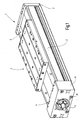
- a linear drive device 1 is illustrated in FIG. 1, the one guide body 2 and one on it has carriage 3 mounted for longitudinal movement.
- the Length of the guide body 2 is almost arbitrary. she will adapted to the respective application.
- the Guide body 2 carries at its two ends 4, 5 bearing housing 6, 7, which cover its entire cross section. These can be held by screws 8, for example be and not as a storage or holding device for one further illustrated engine or gearbox serve that for driving an inside of the guide body 2 arranged drive device 9 ( Figure 2) is used.
- This is formed for example by a threaded spindle 11, whose end 12 protrudes from the bearing housing 6.
- On the threaded spindle 11 is a threaded nut with the carriage 3 is connected.
- Two serve themselves webs 14 extending laterally away from the threaded nut, 15, which lead from the threaded nut to the slide 3.
- the webs 14, 15 are used to support the slide 3 approximately at the same level with the threaded nut rollers 16, 17, 18, 19 (at least three on each side) Unroll rails 21, 22, 23, 24.
- the guide body 2 has, as in particular Figure 2 shows a flat and outer outline rectangular cross-section. From its lower flat Base section 25 project parallel to one another and symmetrically with respect to a central plane 26 side cheeks 27, 28 on, the outside with mounting grooves 29, and if necessary Grooves 31 for accommodating any position sensors can be provided.
- the side cheeks have one Height, which is preferably less than half Width of the base section 25. They are over a bracing Web 32, 33 connected to the base section 25.
- the web 32, 33 delimits the bottom of each Bag, the flanks of which are parallel to each other for the rails 21, 22, 23, 24.
- the webs 32, 33 preferably close to the base section 25 Angle of about 45 °.
- the axes are the rollers 16, 17 perpendicular to the axes of the rollers 18, 19.
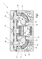
- the side cheeks 27, 28 and the base section 25 enclose an interior 34, the open side by a rigid central profile element 35 at least partially is covered.
- the middle profile element 35 e.g. on Extruded profile, is approximately rectangular in plan view, being its flanks 36, 37 with those parallel to them arranged side walls 27, 28 each have a slot 38 limit the length of the guide body 2 extends.
- the slot 38, 39 is each of reached through the web 14 or 15. Outside the sled it is closed by a masking tape 41, 42, the ends of which, for example, on the bearing housings 6, 7 (FIG 1) are held. Extends in the area of the carriage 3 it through corresponding slot-like longitudinal passages 43, 44, being at the front ends of the carriage in the respective slot 38, 39 returned becomes.
- the slots 38, 39 have on both sides a locking rib 45, 46, 47, 48 on the corresponding Locking lips of the masking tape 41, 42 cooperate to this releasably to hold the respective slot 38, 39. While the locking ribs 45, 48 on the side cheeks 27, 28 are arranged, the locking ribs 46, 47 close immediately on the flanks 36, 37 of the central profile element 35 on.
- the middle profile element 35 is indirectly on the guide body 2 held. Serve as intermediate pieces here a spindle support element 51, as well as other identical 2 lying in front of or behind the support element 51 in FIG. Spindelab 1.5lemente.
- the spindle support element 51, as well as the other spindle support elements are in the interior 34 of the guide body 2 is mounted to be longitudinally displaceable. They have a central opening 52 that the External diameter of the threaded spindle 11 corresponds, so that the spindle support elements 51 against the spindle 11 can be moved, but always a plain bearing form for the threaded spindle 11.
- This is representative of all described spindle support elements 51 is a front view according to FIG. 2 roughly rectangular or square in outline. His Corners, it is provided with guide lugs 53, 54, 55, 56.
- the guide lugs 53, 54 that are adjacent to each other Corners of the spindle support element 51 are arranged, engage in guide grooves 57, 58, which are parallel to each other extend lengthwise through the guide body 2.
- she are one along the flanks to be pointed towards each other continuous depression arranged and open on each other to.
- the flanks of the longitudinal recess also act as a side storage for the Spindelab 100lement. This can bearing projections 61 designed as flat longitudinal ribs, 62 have.
- Center profile element 35 also has a longitudinal recess on the side flanks of guide grooves 63, 64 are formed, which are parallel to each other and extend along the flanks of the longitudinal recess. she open towards each other and take the leading lugs 54, 56.
- the guide lugs 53, 54, 55, 56 and the guide grooves 57, 58, 63, 64 show some play to each other on, so that the longitudinal displaceability of the spindle support elements given is.
- the guide body has one in the embodiment according to Figure 2 no longer used, in cross section rectangular, longitudinally continuous cavity 65 on the is arranged symmetrically to the central plane 26. On the corresponding one, also initially no longer used Cavity 66 is arranged in the carriage 3.
- the two guide grooves 57, 58 together connecting bottom of the longitudinal recess of the base section 25 is a longitudinal groove 67 with a dovetail cross section trained who the recording here no further illustrated insertable profiles serve.
- This are used to define the locking positions of the spindle support elements. These can be, for example, through holes in the profile to be inserted or by appropriate Recesses near the end faces be determined by individual segments of such profiles.
- the Spindle support members include one not shown Locking device that interacts with the profiles.
- the linear drive device described so far 1 works as follows:
- the carriage 3 is positioned by Rotation of the threaded spindle 11.
- the slide runs 3 in a direction parallel to those parallel to each other Rails 21, 22, 23, 24.
- the spindle supports in front of him 51 are released and pushed together.
- In Direction of travel behind the carriage are spindle supports left behind in the defined Locking positions by the element in the longitudinal groove 67 are set.
- Figure 3 is a modified embodiment of the Linear drive device 1 illustrated. This is correct largely with that described in connection with Figures 1 and 2 Embodiment match, so that on the basis same reference numerals completely on the reference is made to the above description. The following also applies following:
- FIG. 4 A further modified embodiment of the linear drive device 1 can be seen in FIG. 4. This agrees with their guide body 2, as well as the the bearing device provided for the slide 3 (rollers 16, 17, 18, 19 and rails 21, 22, 23, 24) with the embodiment according to Figure 2. Accordingly, it gets full based on the same reference numerals to the corresponding parts of the description of the present Figure description referenced. The following also applies:
- the guide body 2 has on the flanks of its in the base portion 25 attached longitudinal recess locking grooves 91, 92 which point towards each other.
- the locking grooves run parallel to each other.
- the guide grooves 57, 58 that in the embodiments described above as a holding device for fastening the middle profile element 35 have served remain unused here.
- the locking grooves 91, 92 serve for fastening a middle profile element 93, which in all embodiments the linear drive device 1 application takes place in which the carriage 3 is actuated by traction means becomes.
- the middle profile element 93 has a parallel the base section 25 arranged web 94 on the its two long narrow sides are parallel to each other extending towards the base section 25 Has locking legs 96, 97. These close via a weakened section 98, 99 to the web 94 on.
- the weakened section 98, 99 allows a certain resilient flexibility of the locking legs 96, 97, see above that these are slightly towards and away from each other can spring.
- the locking legs 96, 97 have support ribs on the outside 101, 102, with which the latching legs 96, 97 engage support the top of the base section 25. At hers On the outside, they are below the support ribs 101, 102 with locking ribs 103, 104 provided in the locking grooves 91, 92 grab.
- the locking ribs 103, 104 can have a sawtooth profile have to snap up vertically the base section 25 inserted into the locking grooves 91, 92 to be able to.
- the middle profile element 93 are inserted lengthways.
- Each side wall 105, 106 carries at the top a plate section 107, 108 which in lie on a common plane and with the top ends complete the side walls 27, 28.
- the plate section 107 defines the slot 38 with the side cheek 27.
- he carries the locking rib 46.
- the plate section 108 which defines the slot 39 with the side cheek 28, bears on its side facing the side cheek 28 Locking rib 47.
- the plate sections 107, 108 delimit between one another a third slot 109.
- For storing a additional masking tapes 111 are on top of each other edges of the plate sections 107, 108 to be pointed 112, 114 arranged.
- the slot 109 is from extends through a web 115, which the carriage 3 with a drive belt or belt running above the web 94 116 connects.
- the belt 116 runs over deflection rollers, which are provided on the bearing housings 6, 7.
- By the Cavity 65 runs the return portion 117 of the belt 116th
- Figure 5 illustrates another embodiment the linear drive device 1, which largely with the Linear drive device 1 corresponds to Figure 4. It will correspond to the description above directed. However, a storage facility deviates from this according to the embodiment of Figure 3 and the associated Description provided. It is based on one or several recirculating ball guides. On the description 3 is based on the same reference numerals directed.
- a linear drive device 1 has a guide body 2, in the interior 35 a holding device is provided by guide grooves 57, 58 and / or locking grooves 91, 92 is formed. These serve the Attachment of a middle profile element 35 or 93 that covers the interior 34 to the outside.
- the middle profile element 35 delimits two slots with the guide body 2 38, 39, which are relatively narrow and with narrow masking tapes 41, 42 can be covered. This will it is possible to use relatively wide, but flat guide bodies 2 provide where the storage facility is arranged on both sides of the base section 25. This results in high rigidity and good guidance of the Carriage 3.
- the different drive concepts enable with one and the same guide body 2.
Landscapes
- Engineering & Computer Science (AREA)
- General Engineering & Computer Science (AREA)
- Mechanical Engineering (AREA)
- Bearings For Parts Moving Linearly (AREA)
Applications Claiming Priority (2)
| Application Number | Priority Date | Filing Date | Title |
|---|---|---|---|
| DE10215832A DE10215832A1 (de) | 2002-04-10 | 2002-04-10 | Linearantriebseinrichtung |
| DE10215832 | 2002-04-10 |
Publications (1)
| Publication Number | Publication Date |
|---|---|
| EP1353093A1 true EP1353093A1 (fr) | 2003-10-15 |
Family
ID=28051238
Family Applications (1)
| Application Number | Title | Priority Date | Filing Date |
|---|---|---|---|
| EP03008255A Withdrawn EP1353093A1 (fr) | 2002-04-10 | 2003-04-09 | Actuateur linéaire |
Country Status (2)
| Country | Link |
|---|---|
| EP (1) | EP1353093A1 (fr) |
| DE (1) | DE10215832A1 (fr) |
Cited By (4)
| Publication number | Priority date | Publication date | Assignee | Title |
|---|---|---|---|---|
| EP2110201A1 (fr) * | 2008-04-15 | 2009-10-21 | Festo AG & Co. KG | Entraînement linéaire électrique |
| CN103192275A (zh) * | 2012-01-06 | 2013-07-10 | 沈阳新松机器人自动化股份有限公司 | 立柱结构 |
| CN104942610A (zh) * | 2014-03-25 | 2015-09-30 | 财团法人金属工业研究发展中心 | 气静压平台 |
| CN106826263A (zh) * | 2015-12-04 | 2017-06-13 | 财团法人金属工业研究发展中心 | 气静压平台及其间隙调整方法 |
Families Citing this family (1)
| Publication number | Priority date | Publication date | Assignee | Title |
|---|---|---|---|---|
| DE102004057714A1 (de) * | 2004-11-30 | 2006-06-01 | Accuride International Gmbh | Linearführungssystem mit Stellelementen |
Citations (4)
| Publication number | Priority date | Publication date | Assignee | Title |
|---|---|---|---|---|
| EP0327705A1 (fr) * | 1988-02-11 | 1989-08-16 | Neff Gmbh | Dispositif mécanique d'actionnement linéaire |
| DE19636272A1 (de) * | 1996-09-06 | 1998-03-12 | Star Gmbh | Linearführungseinrichtung |
| DE20002865U1 (de) * | 1999-04-26 | 2000-05-18 | Rexroth Star GmbH, 97424 Schweinfurt | Lineareinheit |
| DE10107076A1 (de) * | 2000-02-18 | 2001-09-06 | Smc Kk | Linearstellglied |
Family Cites Families (1)
| Publication number | Priority date | Publication date | Assignee | Title |
|---|---|---|---|---|
| DE10002849C2 (de) * | 2000-01-24 | 2002-03-28 | Rexroth Star Gmbh | Lineareinheit |
-
2002
- 2002-04-10 DE DE10215832A patent/DE10215832A1/de not_active Withdrawn
-
2003
- 2003-04-09 EP EP03008255A patent/EP1353093A1/fr not_active Withdrawn
Patent Citations (4)
| Publication number | Priority date | Publication date | Assignee | Title |
|---|---|---|---|---|
| EP0327705A1 (fr) * | 1988-02-11 | 1989-08-16 | Neff Gmbh | Dispositif mécanique d'actionnement linéaire |
| DE19636272A1 (de) * | 1996-09-06 | 1998-03-12 | Star Gmbh | Linearführungseinrichtung |
| DE20002865U1 (de) * | 1999-04-26 | 2000-05-18 | Rexroth Star GmbH, 97424 Schweinfurt | Lineareinheit |
| DE10107076A1 (de) * | 2000-02-18 | 2001-09-06 | Smc Kk | Linearstellglied |
Cited By (5)
| Publication number | Priority date | Publication date | Assignee | Title |
|---|---|---|---|---|
| EP2110201A1 (fr) * | 2008-04-15 | 2009-10-21 | Festo AG & Co. KG | Entraînement linéaire électrique |
| CN103192275A (zh) * | 2012-01-06 | 2013-07-10 | 沈阳新松机器人自动化股份有限公司 | 立柱结构 |
| CN104942610A (zh) * | 2014-03-25 | 2015-09-30 | 财团法人金属工业研究发展中心 | 气静压平台 |
| CN104942610B (zh) * | 2014-03-25 | 2017-08-15 | 财团法人金属工业研究发展中心 | 气静压平台 |
| CN106826263A (zh) * | 2015-12-04 | 2017-06-13 | 财团法人金属工业研究发展中心 | 气静压平台及其间隙调整方法 |
Also Published As
| Publication number | Publication date |
|---|---|
| DE10215832A1 (de) | 2003-10-30 |
Similar Documents
| Publication | Publication Date | Title |
|---|---|---|
| EP0340751B2 (fr) | Unité de guidage rectiligne | |
| EP0327705B1 (fr) | Dispositif mécanique d'actionnement linéaire | |
| DE19532759B4 (de) | Linearführungseinheit | |
| DE4492258C1 (de) | Führungsschiene für rollende Lastenträger | |
| DE3313128A1 (de) | Lageranordnung zur geradlinigen fuehrung eines schlittens laengs einer fuehrungsschiene | |
| DE60100438T2 (de) | Lineare Lenksäulenführungseinrichtung | |
| DE3629368C2 (fr) | ||
| EP0941889B1 (fr) | Dispositif d'extraction | |
| DE3423504A1 (de) | Befestigungsvorrichtung | |
| WO1998005469A1 (fr) | Chassis de guidage | |
| EP0790421A1 (fr) | Guide linéaire | |
| DE60317846T2 (de) | Linearführungseinheit | |
| DE8715922U1 (de) | Mechanische Lineareinheit | |
| AT402092B (de) | Linearführung | |
| EP1353093A1 (fr) | Actuateur linéaire | |
| EP0918174A2 (fr) | Actionneur linéaire à entraínement motorisé | |
| DE3532103A1 (de) | Rahmenanordnung fuer ein fahrzeugdach | |
| DD249429A5 (de) | Schlittenfuehrungssystem | |
| EP0181499B1 (fr) | Dispositif de guidage longitudinal pour siège de véhicule comportant une glissière extérieure à profil en forme de C et une glissière intérieure à profil en forme de chapeau | |
| DE4327203C2 (de) | Vorrichtung zum Archivieren von Kassetten | |
| DE9112285U1 (de) | Linearführung | |
| DE3713097A1 (de) | Teleskopabdeckung | |
| DE102022000249A1 (de) | Linearprofil und Lineareinheit | |
| AT410978B (de) | Wasserwaage mit einem hohlprofil | |
| DE202022000185U1 (de) | Linearprofil und Lineareinheit |
Legal Events
| Date | Code | Title | Description |
|---|---|---|---|
| PUAI | Public reference made under article 153(3) epc to a published international application that has entered the european phase |
Free format text: ORIGINAL CODE: 0009012 |
|
| AK | Designated contracting states |
Kind code of ref document: A1 Designated state(s): AT BE BG CH CY CZ DE DK EE ES FI FR GB GR HU IE IT LI LU MC NL PT RO SE SI SK TR |
|
| AX | Request for extension of the european patent |
Extension state: AL LT LV MK |
|
| 17P | Request for examination filed |
Effective date: 20040325 |
|
| 17Q | First examination report despatched |
Effective date: 20040423 |
|
| AKX | Designation fees paid |
Designated state(s): AT CH DE FR GB IT LI |
|
| RAP1 | Party data changed (applicant data changed or rights of an application transferred) |
Owner name: TOLLO LINEAR AB |
|
| STAA | Information on the status of an ep patent application or granted ep patent |
Free format text: STATUS: THE APPLICATION IS DEEMED TO BE WITHDRAWN |
|
| 18D | Application deemed to be withdrawn |
Effective date: 20081105 |