EP1353531A2 - Akustischer Wandler mit reduzierter Dicke - Google Patents
Akustischer Wandler mit reduzierter Dicke Download PDFInfo
- Publication number
- EP1353531A2 EP1353531A2 EP03076036A EP03076036A EP1353531A2 EP 1353531 A2 EP1353531 A2 EP 1353531A2 EP 03076036 A EP03076036 A EP 03076036A EP 03076036 A EP03076036 A EP 03076036A EP 1353531 A2 EP1353531 A2 EP 1353531A2
- Authority
- EP
- European Patent Office
- Prior art keywords
- transducer
- membrane
- housing
- coil
- cover
- Prior art date
- Legal status (The legal status is an assumption and is not a legal conclusion. Google has not performed a legal analysis and makes no representation as to the accuracy of the status listed.)
- Granted
Links
Images


Classifications
-
- H—ELECTRICITY
- H04—ELECTRIC COMMUNICATION TECHNIQUE
- H04R—LOUDSPEAKERS, MICROPHONES, GRAMOPHONE PICK-UPS OR LIKE ACOUSTIC ELECTROMECHANICAL TRANSDUCERS; ELECTRIC HEARING AIDS; PUBLIC ADDRESS SYSTEMS
- H04R11/00—Transducers of moving-armature or moving-core type
- H04R11/02—Loudspeakers
-
- H—ELECTRICITY
- H04—ELECTRIC COMMUNICATION TECHNIQUE
- H04R—LOUDSPEAKERS, MICROPHONES, GRAMOPHONE PICK-UPS OR LIKE ACOUSTIC ELECTROMECHANICAL TRANSDUCERS; ELECTRIC HEARING AIDS; PUBLIC ADDRESS SYSTEMS
- H04R31/00—Apparatus or processes specially adapted for the manufacture of transducers or diaphragms therefor
- H04R31/006—Interconnection of transducer parts
-
- H—ELECTRICITY
- H04—ELECTRIC COMMUNICATION TECHNIQUE
- H04R—LOUDSPEAKERS, MICROPHONES, GRAMOPHONE PICK-UPS OR LIKE ACOUSTIC ELECTROMECHANICAL TRANSDUCERS; ELECTRIC HEARING AIDS; PUBLIC ADDRESS SYSTEMS
- H04R25/00—Electric hearing aids
Definitions
- the invention relates to miniature receivers used in listening devices, such as hearing aids.
- the present invention relates to a receiver having one or more improved constructional features including, but not limited to a reduced thickness.
- a conventional hearing aid or listening device includes a microphone that receives acoustic sound waves and converts the acoustic sound waves to an audio (frequency) (electrical) signal. That "audio signal” is then processed (e.g., amplified) and sent to the receiver of the hearing aid or listening device. The receiver then converts the processed signal to a corresponding acoustic signal that is broadcast toward the eardrum.
- audio signal e.g., amplified
- a conventional hearing aid or listening device can include both a microphone and a telecoil for receiving inputs.
- the telecoil picks up electromagnetic (broadcast) signals.
- the telecoil produces a signal voltage across its terminals when placed within an electromagnetic field, which is created by an alternating current of an audio frequency electromagnetic signal moving through a wire.
- the signal in the telecoil is then processed (e.g. amplified) and sent to the transducer (or receiver) of the hearing aid for conversion to a corresponding acoustic signal.
- a typical "hearing aid” comprises a combination of a receiver and a microphone in one housing or “case.”
- the signal from the microphone to the receiver is amplified before the receiver broadcasts the acoustic signal toward the eardrum.
- the housing or "case” is made of a soft magnetic material, such as a nickel-iron alloy.
- the case serves several functions: firstly, its housing provides some level of sturdiness; secondly, it provides a structure for supporting the components and their electrical connections. Thirdly, the case provides both magnetic and electrical shielding. Lastly, the case may provide acoustical and vibrational isolation to the other parts of the hearing aid.
- the broadcasting of the acoustic signal causes the receiver to vibrate.
- the vibrations can affect the overall performance of the listening device. For example, the vibrations in the receiver can be transmitted back to the microphone, causing unwanted feedback.
- a magnetic feedback signal may create feedback problems. Consequently, it is desirable to reduce the amount of vibrations and/or magnetic feedback that occur in the receiver of the hearing aid or listening device.
- FIGS. 1 and 2 Typical such transducers/receivers are shown in FIGS. 1 and 2. While the receivers 10 and 10a shown in FIGS. 1 and 2 are essentially of the same configuration, they differ primarily in the design of the armature, FIG. 1 illustrating a so-called E-type armature 12, and FIG. 2 showing a U-type armature 12a. Accordingly, like reference numerals with the suffix "a" are used to designate the like parts and components of the receiver of FIG. 2, whereby the components of the receiver of FIG. 10 will be described in detail, it being understood that the components of the receiver of 10a of FIG. 2 are essentially the same.
- a housing surrounds the working components of the receiver 10 and includes a case 14 and a cover 15.
- One end of the housing includes an output port 16 for transmitting the acoustical signal toward the users eardrum.
- An opposite end of the housing may include an electrical connector assembly 18 which may include provisions for various types of contacts or electrical connections such as by soldering or the like. This connector 18 receives an input audio frequency electrical signal that is converted by the internal working components of the receiver to an output acoustic signal (sound waves) which is broadcast from the output port 16.
- the working components of the transducer or receiver 10 include a motor 20 which includes a magnet assembly 22 and a coil 24 which are coaxially located and in side-by-side abutting alignment.
- a motor 20 which includes a magnet assembly 22 and a coil 24 which are coaxially located and in side-by-side abutting alignment.
- a moveable armature 12 Through an axial center of the coil 24 and magnet assembly 22 is a moveable armature 12, which is moved in response to the electromagnetic forces produced by the magnet assembly 22 and coil 24 in response to the applied audio frequency electrical signal at the terminal 18.
- the corresponding motion of the armature 12 may be translated into acoustic energy (sound waves) by a diaphragm 30 which is mounted in the case 14 above the magnet assembly 22 and coil 24 and is operatively coupled with the armature 12 by a drive pin 32.
- the overall thickness of the receiver 10 is defined by the thickness of the walls of the case 14 and cover 15, the thickness of the magnet assembly 22, which includes a magnet 26 and a magnet housing 28 surrounding the magnet 26, the diaphragm 30 and sufficient free airspace to permit vibration of the diaphragm to create acoustic energy or sound waves in response to the operation of the motor 20 as described above.
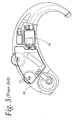
- hearing aids it is generally desirable to decrease overall size of components where possible, and in particular, for hearing aides such as a behind the ear (BTE) hearing aid 40 (see FIG. 3) or "in the ear” (ITE) hearing aid (not shown).
- BTE behind the ear
- ITE in the ear
- the overall width of the hearing aid is essentially determined by the thickness of the receiver.
- an additional element to the overall thickness to the receiver is the second arm of the U-shaped armature 12a as indicated at reference numeral 12b.
- a transducer for a hearing aid comprises a housing, a relatively thin membrane suspended in said housing for vibration in response to a motor, said motor comprising a coil and a magnet assembly, said coil being mounted in said housing beneath said membrane; said magnet assembly being mounted in said housing coaxially with said coil to one edge of said membrane.
- a dual transducer for a hearing aid comprises a pair of transducers mounted in side-by-side abutting relation, each of said transducers comprises a housing, a relatively thin membrane having a free end and suspended in said housing for vibration in response to a motor, said motor comprising a coil and a magnet assembly, said coil being mounted in said housing beneath said membrane; said magnet assembly being mounted in said housing coaxially with said coil and to one edge of said membrane, wherein each said housing comprises a case and a cover with said membrane being spaced beneath and parallel with said cover and wherein said transducers are mounted with said cases in congruently aligned and abutting condition.
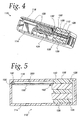
- a transducer (receiver) in accordance with the invention is designated generally by the reference numeral 110, and includes generally the same type of components as those described with respect to the transducer/receiver of FIG. 1 hereinabove. Accordingly, like reference numerals with the prefix 1 are used to designate similar parts and components.
- the receiver is housed in a housing which comprises a case 114 and a cover 116.
- An armature 112 extends through central openings of a coil 124 and a magnet assembly 122, which together form a motor for driving the armature 112.
- the magnet assembly 122 is in turn constructed of a magnet 126 surrounded by a magnet housing 128.
- the armature is connected by way of a drive pin 132 to drive a diaphragm 130 which is spaced between the coil 124 and cover 116 to allow for vibration in response to the action of the motor which in turn is responsive to an incoming electroacoustical or audio frequency electrical signal.
- the magnet assembly 122 rather than being located beneath the diaphragm 130, is located spaced slightly to one side of the diaphragm 130, however, still coaxially aligned with the coil 124.
- the magnet housing 128 extends into and through an opening 150 provided in registry therewith in the cover 116.
- the cover 116 may be extended outwardly somewhat so as to abut and completely cover the housing 128, in the same fashion as the manner in which the case 114 covers the lower part of the magnet housing 128. In either case, it will be seen that the overall thickness of the transducer 110 of FIG. 4 will be substantially less than that of the assembly of either FIG. 1 or FIG.
- the magnet assembly 122 is also spaced laterally from the coil somewhat to create a space through which the drive pin 132 may extend to the diaphragm or membrane 130 to transmit vibrations from the armature, corresponding to the incoming audio frequency electrical signal.
- the transducer 110 can be modified to act as a microphone with an incoming acoustic or sound pressure signal vibrating the membrane 130 and the membrane in turn imparting vibratory motion to the armature causing a corresponding change in the electrical magnetic field of the magnet and coil 120, 124 which can be translated into an electrical output signal.
- the present invention is illustrated and described herein primarily by reference to use of the transducer 110 as a receiver.
- FIG. 5 shows a partially assembled sectional view, similar to the section shown in FIG. 4, of a transducer 110 having a different means of attachment of the membrane.
- the transducer 110 has similar parts and components to the transducer 110 of FIG. 4 in these parts and components are indicated by like reference numerals. Briefly, these components include a case made up of a base 114 and cover 116, a magnet 126 and a magnet housing 128, which in the embodiment shown in FIG. 5 extends flush with a top of the cover 116 through an opening 150 therein.
- the membrane is carried on a foil carrier 200 (as in FIGS. 16-18, described below).
- the carrier 200 may be clamped between the case 114 and cover 116 about a peripheral edge as indicated generally at reference numeral 155. However, at the embodiment shown in FIG. 5, one edge of the carrier 200 is attached to the magnet 126. In this regard, an additional vibration damping fold 160 is provided adjacent the attachment of the carrier 200 to the magnet 126.
- the drop or quantity of adhesive 142 for securing the drive pin 132 (not shown in FIG. 5) to the membrane 130 is also shown.
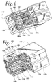
- FIGS. 6 and 7 illustrate identical transducers or receivers 110 and 110a which are constructed as described with reference to FIG. 4, and mounted in back-to-back alignment.
- Such dual-use receivers may be utilized to increase the acoustic output in response to an incoming audio frequency electrical signal, in applications where such an increase is desired. Further details of the construction of such dual receivers will be described later. Suffice it to say that in the embodiments of FIGS. 5 and 6 the orientations of the two receivers 110 and 110a are respectively reversed, that is, in FIG. 5, the cover portions 116 of the housing are aligned and joined, whereas in the embodiment of FIG. 6 the case portions 114 of the two housings are aligned and joined.
- FIGS. 8a and 8b two embodiments of the coil 124a and 124b are shown, together with the membrane 130. It will be seen that the membrane 130 is convexly curved to overlie and partially surround an upper (as viewed in FIGS. 8a and 8b) surface of the coil 124a, 124b. While the shape of the coil 124a is essentially round, the coil 124b illustrates a pronounced oval shape. In this regard, either conventional wire or self-bonding type wires may be used to form the coil.
- FIG. 9 a novel and improved manner of attaching the drive pin 132 to the membrane 130 is shown.
- the drive pin extends through the membrane 130, by way of a through opening or aperture 136 as shown for example in FIG. 10 or through an edge recess or slot 138 as shown in FIG. 11.
- a quantity of adhesive 142 is placed between the bent over end 133 of the drive pin 132 and a facing surface of the membrane 130. This permits the glue to or other adhesive to flow relatively naturally into the area between the drive pin end 133 and the facing surface of the membrane 130. This in turn minimizes the chance of the glue spreading into areas of the membrane where it is not intended to.
- the membrane 130 with the hole 136 or alternate membrane 130a with the edge slot 138 are shown in a novel and improved "three point" driving system.
- the drive pin forms one point of a triangle and the corners along an opposite edge of the membrane 130 form the other two points, by means of a hinged connection illustrated diagrammatically at 150 and 152 to the case 114 (not shown in FIGS. 10 and 11). This helps in maintaining a proper positioning of the membrane in three dimensions and to achieve as high a compliance as possible.
- damping of the membrane may be obtained by the use of damping paste attached between the facing edges of the membrane 130 and the receiver housing or case 114.
- this is achieved by folding or bending over opposite edge portions 160, 162 of the membrane at an angle of 90° and introducing the damping material 170 between these folded up edges and facing inside surfaces of the case 114.
- these opposed edges 160 and 162 of the membrane 30 are folded or bent in the opposite direction and the damping paste is introduced.
- respective caps 180 and 182 are introduced in the area overlying the damping paste 170.
- the gap between the facing surfaces of the membrane 130 and case 114 is somewhat wider on one side whereby the corresponding cap 182 is somewhat wider than the cap 180.
- the coil 124 and magnet assembly 122 are mounted on a printed circuit board (PCB) 190.
- PCB 190 which provides a relatively rigid planar surface, allows precise positioning of the coil and magnet in aligned, spaced apart and coaxial condition, whereby the armature 112 and drive pin 132 can also be more precisely positioned.
- the PCB 190 may be supported by the case 114 and may extend therethrough at one end as indicated at reference numeral 192 to define the connector or soldering pad 118 which may be coupled to receive the incoming audio frequency electrical signal by means of a connector 195.
- the same structural features are shown in FIG. 15 for a dual receiver or dual transducer assembly of the type shown in FIG. 7.
- the leads of the coil can be soldered or welded to the PCB and the leads of the coil can be prepped prior to direct soldering or welding to the PCB or alternatively prepped and lead outwardly of the housing for external connection.
- the coil and magnet may be partially covered by epoxy resin (not shown) to protect the wires from oxidation and provide added mechanical strength.
- the PCB permits the addition of other components, such as an amplifier to create an integrated transducer/amplifier or receiver or receiver/amplifier.
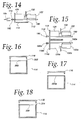
- FIGS. 16-18 there is shown diagrammatically several ways of attaching a foil 200, which acts as a carrier for the membrane 130, to the housing.
- a foil of increased thickness that is, compared to the thickness of foil usually used
- a foil of conventional thickness is utilized.
- an extra, relatively thin strip or "ring" 202 of the same foil material is interposed about the periphery of the foil 200.
- FIG. 16 an extra, relatively thin strip or "ring" 202 of the same foil material is interposed about the periphery of the foil 200.
- FIGS. 16-18 a similar effect is achieved by using a foil 200 of increased area and bending or folding back edges thereof as indicated at 204 to create a double layer in the area where the foil is clamped between the cover 16 and case 114.
- the extra foil material 202, 204 is interposed between the foil 200 and the cover 116, although this layer might be interposed between the foil 200 and the base 114, if desired.
- the embodiment of FIGS. 16-18 allow the foil to be attached to the case in such a way as to seal the contents of the case, and provide an air tight motor chamber, without using any glue or other adhesive.
- the magnet assembly 122 may be further improved by constructing the magnet 126 of a rare earth magnet material such as neodymium or samarium.
- a rare earth magnet material such as neodymium or samarium.
- the specifications of these materials are such that the same amount of magnetic flux can be achieved using less magnetic material, which further allows a decrease of the dimensions of the magnet and magnet housing assembly.
- a number of considerations arise when using a dual transducer or dual receiver configuration. Firstly, it is difficult or impossible to compensate for lateral movements or vibrations of the receiver, that is, in a plane transverse to the plane of vibration of the membrane.
- U-shaped armatures tend to have greater lateral movements, compared to an E-shaped armature which tends to work more or less like a cantilever. Any rotational movement or vibration can only be compensated when the center of the rotation is the same, or reduced by placing the centers as close together as possible.
- a dual receiver will preferably be built with E-type armatures and configured as shown in FIG. 7 in a back-to-back configuration which places the centers of rotation closer together than in the configuration shown in FIG. 6.
- Dual receivers are commonly matched by magnetizing one or both in such a way that the sensitivities match at a certain frequency, usually 1 KHz or lower.
- the receiver should be matched for output at a peak frequency or other predetermined frequency. This can be done by sorting the receivers into groups and selecting matching receivers according to the foregoing and/or other predefined criteria.
- the configuration wherein the magnet housing extends through the cover also helps in magnetizing the receivers for matching purposes, otherwise it would have to be done with the covers removed.
- FIG. 7 with the mounting of the magnet and coil to the PCB, there is sufficient stability to magnetize with a temporary case or plate to close the bottom.
- this dummy cover or plate can be removed and the two cases can be welded together. Also, the PCBs with their connecting pads are much closer together in this configuration which permits them to be integrated into a single electrical connector, for example, so that a single micro push-on or micro socket connector such as the connector 195 can be used.
Landscapes
- Engineering & Computer Science (AREA)
- Physics & Mathematics (AREA)
- Acoustics & Sound (AREA)
- Signal Processing (AREA)
- Manufacturing & Machinery (AREA)
- Electromagnetism (AREA)
- Electrostatic, Electromagnetic, Magneto- Strictive, And Variable-Resistance Transducers (AREA)
- Transducers For Ultrasonic Waves (AREA)
- Piezo-Electric Transducers For Audible Bands (AREA)
Priority Applications (1)
| Application Number | Priority Date | Filing Date | Title |
|---|---|---|---|
| EP10183989A EP2271131A3 (de) | 2002-04-09 | 2003-04-08 | Akustischer Wandler mit reduzierter Dicke |
Applications Claiming Priority (2)
| Application Number | Priority Date | Filing Date | Title |
|---|---|---|---|
| US10/118,791 US7190803B2 (en) | 2002-04-09 | 2002-04-09 | Acoustic transducer having reduced thickness |
| US118791 | 2002-04-09 |
Related Child Applications (1)
| Application Number | Title | Priority Date | Filing Date |
|---|---|---|---|
| EP10183989.2 Division-Into | 2010-09-30 |
Publications (3)
| Publication Number | Publication Date |
|---|---|
| EP1353531A2 true EP1353531A2 (de) | 2003-10-15 |
| EP1353531A3 EP1353531A3 (de) | 2006-04-12 |
| EP1353531B1 EP1353531B1 (de) | 2011-08-10 |
Family
ID=28453974
Family Applications (2)
| Application Number | Title | Priority Date | Filing Date |
|---|---|---|---|
| EP10183989A Withdrawn EP2271131A3 (de) | 2002-04-09 | 2003-04-08 | Akustischer Wandler mit reduzierter Dicke |
| EP03076036A Expired - Lifetime EP1353531B1 (de) | 2002-04-09 | 2003-04-08 | Akustischer Wandler mit reduzierter Dicke |
Family Applications Before (1)
| Application Number | Title | Priority Date | Filing Date |
|---|---|---|---|
| EP10183989A Withdrawn EP2271131A3 (de) | 2002-04-09 | 2003-04-08 | Akustischer Wandler mit reduzierter Dicke |
Country Status (4)
| Country | Link |
|---|---|
| US (2) | US7190803B2 (de) |
| EP (2) | EP2271131A3 (de) |
| AT (1) | ATE520262T1 (de) |
| DK (1) | DK1353531T3 (de) |
Cited By (11)
| Publication number | Priority date | Publication date | Assignee | Title |
|---|---|---|---|---|
| EP2146521A1 (de) * | 2008-07-18 | 2010-01-20 | BYD Company Limited | Ohrstück für mobile Kommunikation mit Schwinganker |
| EP2466915A3 (de) * | 2010-12-14 | 2013-01-16 | Sonion Nederland B.V. | Mehrschichtige Armatur für einen Lautsprecher mit beweglicher Armatur |
| EP2107828A3 (de) * | 2008-04-02 | 2013-05-22 | Sonion Nederland B.V. | Anordnung mit einem Tonausgabegerät und zwei Tondetektoren |
| EP2503792A3 (de) * | 2011-03-21 | 2013-09-18 | Sonion Nederland B.V. | Lautsprecher mit beweglichem Anker mit Vibrationsunterdrückung |
| EP2464141A3 (de) * | 2010-12-07 | 2013-10-16 | Sonion Nederland B.V. | Motoranordnung |
| EP1895811A3 (de) * | 2006-08-28 | 2014-08-06 | Sonion Nederland B.V. | Mehrere Lautsprecher mit einem gemeinsamen Schallauslassrohr |
| EP3051841A1 (de) * | 2015-01-30 | 2016-08-03 | Sonion Nederland B.V. | Hörer mit aufgehängter motoranordnung |
| US9473855B2 (en) | 2011-03-21 | 2016-10-18 | Sonion Nederland B.V. | Moving armature receiver assemblies with vibration suppression |
| EP3293985A1 (de) * | 2016-09-12 | 2018-03-14 | Sonion Nederland B.V. | Hörer mit integrierter membranbewegungserkennung |
| EP3337192A1 (de) | 2016-12-16 | 2018-06-20 | Sonion Nederland B.V. | Empfängeranordnung |
| EP3337191A1 (de) | 2016-12-16 | 2018-06-20 | Sonion Nederland B.V. | Empfängeranordnung |
Families Citing this family (90)
| Publication number | Priority date | Publication date | Assignee | Title |
|---|---|---|---|---|
| US7362878B2 (en) * | 2004-06-14 | 2008-04-22 | Knowles Electronics, Llc. | Magnetic assembly for a transducer |
| WO2006122010A1 (en) * | 2005-05-09 | 2006-11-16 | Knowles Electronics, Llc | Conjoined receiver and microphone assembly |
| US20070025572A1 (en) * | 2005-08-01 | 2007-02-01 | Forte James W | Loudspeaker |
| US7680292B2 (en) * | 2006-05-30 | 2010-03-16 | Knowles Electronics, Llc | Personal listening device |
| KR100795306B1 (ko) * | 2006-08-21 | 2008-01-15 | 권유정 | 귓속 보청기용 페이스 플레이트의 제조방법 |
| DE102007031872B4 (de) * | 2007-07-09 | 2009-11-19 | Siemens Audiologische Technik Gmbh | Hörgerät |
| US8135163B2 (en) * | 2007-08-30 | 2012-03-13 | Klipsch Group, Inc. | Balanced armature with acoustic low pass filter |
| US20090143097A1 (en) * | 2007-11-30 | 2009-06-04 | Palm, Inc. | PCB coil for hearing aid compatibility compliance |
| US20100034418A1 (en) * | 2008-08-11 | 2010-02-11 | Seagate Technology Llc | High performance micro speaker |
| US8295536B2 (en) * | 2010-03-31 | 2012-10-23 | Bose Corporation | Moving magnet levered loudspeaker |
| US8295537B2 (en) * | 2010-03-31 | 2012-10-23 | Bose Corporation | Loudspeaker moment and torque balancing |
| US8548186B2 (en) | 2010-07-09 | 2013-10-01 | Shure Acquisition Holdings, Inc. | Earphone assembly |
| US8549733B2 (en) | 2010-07-09 | 2013-10-08 | Shure Acquisition Holdings, Inc. | Method of forming a transducer assembly |
| US8538061B2 (en) * | 2010-07-09 | 2013-09-17 | Shure Acquisition Holdings, Inc. | Earphone driver and method of manufacture |
| US20120280579A1 (en) * | 2011-05-06 | 2012-11-08 | Bose Corporation | Linear moving magnet motor cogging force ripple reducing |
| DK2730097T3 (en) | 2011-07-07 | 2019-12-09 | Sonion Nederland Bv | A multiple receiver assembly and a method for assembly thereof |
| WO2013138234A1 (en) * | 2012-03-16 | 2013-09-19 | Knowles Electronics, Llc | A receiver with a non-uniform shaped housing |
| US9020173B2 (en) * | 2012-05-17 | 2015-04-28 | Starkey Laboratories, Inc. | Method and apparatus for harvesting energy in a hearing assistance device |
| US9055370B2 (en) | 2012-08-31 | 2015-06-09 | Bose Corporation | Vibration-reducing passive radiators |
| EP2723102B1 (de) | 2012-10-18 | 2018-09-05 | Sonion Nederland B.V. | Wandler, Hörgerät mit dem Wandler und Verfahren zum Betrieb des Wandlers |
| US9066187B2 (en) | 2012-10-18 | 2015-06-23 | Sonion Nederland Bv | Dual transducer with shared diaphragm |
| DK2747459T3 (en) | 2012-12-21 | 2018-12-17 | Sonion Nederland Bv | RIC unit with Thuras tube |
| CN103079159A (zh) * | 2012-12-25 | 2013-05-01 | 苏州恒听电子有限公司 | 一种动铁单元的屏蔽外壳及其助听设备 |
| DK2750413T3 (en) | 2012-12-28 | 2017-05-22 | Sonion Nederland Bv | Hearing aid |
| US9401575B2 (en) | 2013-05-29 | 2016-07-26 | Sonion Nederland Bv | Method of assembling a transducer assembly |
| US20140355787A1 (en) * | 2013-05-31 | 2014-12-04 | Knowles Electronics, Llc | Acoustic receiver with internal screen |
| US9137605B2 (en) * | 2013-06-17 | 2015-09-15 | Knowles Electronics, Llc | Formed diaphragm frame for receiver |
| KR20150004079A (ko) * | 2013-07-02 | 2015-01-12 | 삼성전자주식회사 | 밸런스드 아마추어 트랜스듀서의 성능 개선 장치 |
| DK2849463T3 (en) | 2013-09-16 | 2018-06-25 | Sonion Nederland Bv | Transducer with moisture transporting element |
| JP2015080064A (ja) * | 2013-10-16 | 2015-04-23 | モレックス インコーポレイテドMolex Incorporated | 電気音響変換器 |
| DK3550852T3 (en) | 2014-02-14 | 2021-02-01 | Sonion Nederland Bv | A joiner for a receiver assembly |
| EP2908559B1 (de) | 2014-02-18 | 2016-10-05 | Sonion A/S | Verfahren zur Herstellung von Anordnungen für Hörgeräte |
| EP2914018B1 (de) | 2014-02-26 | 2016-11-09 | Sonion Nederland B.V. | Lautsprecher, verankerung und verfahren |
| US9432774B2 (en) * | 2014-04-02 | 2016-08-30 | Sonion Nederland B.V. | Transducer with a bent armature |
| EP2953380A1 (de) | 2014-06-04 | 2015-12-09 | Sonion Nederland B.V. | Akustische Übersprechkompensation |
| US20150373456A1 (en) * | 2014-06-19 | 2015-12-24 | Knowles Electronics, Llc | Torsion Diaphragm Apparatus |
| US10063958B2 (en) | 2014-11-07 | 2018-08-28 | Microsoft Technology Licensing, Llc | Earpiece attachment devices |
| US9888322B2 (en) * | 2014-12-05 | 2018-02-06 | Knowles Electronics, Llc | Receiver with coil wound on a stationary ferromagnetic core |
| US9872109B2 (en) | 2014-12-17 | 2018-01-16 | Knowles Electronics, Llc | Shared coil receiver |
| US9729974B2 (en) | 2014-12-30 | 2017-08-08 | Sonion Nederland B.V. | Hybrid receiver module |
| KR20160081641A (ko) * | 2014-12-31 | 2016-07-08 | 도시바삼성스토리지테크놀러지코리아 주식회사 | 이어폰 및 이어폰 제작 방법 |
| DK3057339T3 (da) | 2015-02-10 | 2021-01-04 | Sonion Nederland Bv | Mikrofonmodul med fælles midterste lydindgangsanordning |
| EP3073765B1 (de) * | 2015-03-25 | 2022-08-17 | Sonion Nederland B.V. | Anordnung eines hörers in einem gehörgang mit einer membran und einer kabelverbindung |
| EP3073764B1 (de) | 2015-03-25 | 2021-04-21 | Sonion Nederland B.V. | Hörgerät mit einem einsatzelement |
| US9992579B2 (en) | 2015-06-03 | 2018-06-05 | Knowles Electronics, Llc | Integrated yoke and armature in a receiver |
| DK3133829T3 (da) | 2015-08-19 | 2020-06-22 | Sonion Nederland Bv | Lydgiverenhed med forbedret frekvensrespons |
| DK3139627T3 (da) | 2015-09-02 | 2019-05-20 | Sonion Nederland Bv | Høreanordning med flervejslydgivere |
| US9668065B2 (en) | 2015-09-18 | 2017-05-30 | Sonion Nederland B.V. | Acoustical module with acoustical filter |
| US10021494B2 (en) | 2015-10-14 | 2018-07-10 | Sonion Nederland B.V. | Hearing device with vibration sensitive transducer |
| DK3160157T3 (en) | 2015-10-21 | 2018-12-17 | Sonion Nederland Bv | Vibration-compensated vibroacoustic device |
| DK3177037T3 (en) | 2015-12-04 | 2020-10-26 | Sonion Nederland Bv | Balanced armature receiver with bi-stable balanced armature |
| DK3185584T3 (da) | 2015-12-21 | 2020-07-20 | Sonion Nederland Bv | Lydgiveranordning med en udpræget længderetning |
| EP3197046B1 (de) | 2016-01-25 | 2021-04-14 | Sonion Nederland B.V. | Selbstvorspannender ausgangsboosterverstärker und verwendung davon |
| EP3200479A3 (de) | 2016-01-28 | 2017-08-30 | Sonion Nederland B.V. | Elektrostatischer schallgenerator und anordnung mit elektrostatischem schallgenerator und transformator |
| DE102016202658A1 (de) * | 2016-02-22 | 2017-08-24 | Sivantos Pte. Ltd. | Lautsprechermodul für ein Hörgerät und Hörgerät |
| US11082778B2 (en) | 2016-03-18 | 2021-08-03 | Knowles Electronics, Llc | Driver with acoustic filter chamber |
| EP3232685B1 (de) | 2016-04-13 | 2021-03-03 | Sonion Nederland B.V. | Kuppel für eine persönliche audio-nachrichtenvorrichtung |
| US10078097B2 (en) | 2016-06-01 | 2018-09-18 | Sonion Nederland B.V. | Vibration or acceleration sensor applying squeeze film damping |
| DK3279621T4 (da) | 2016-08-26 | 2025-04-28 | Sonion Nederland Bv | Vibrationssensor med lavfrekvent roll-off-responskurve |
| DK3313097T3 (da) | 2016-10-19 | 2020-10-19 | Sonion Nederland Bv | An ear bud or dome |
| EP3324538A1 (de) | 2016-11-18 | 2018-05-23 | Sonion Nederland B.V. | Messschaltung mit einer verstärkerschaltung |
| EP3324645A1 (de) | 2016-11-18 | 2018-05-23 | Sonion Nederland B.V. | Phasenkorrigierendes system und phasenkorrigierbares wandlersystem |
| US10264361B2 (en) | 2016-11-18 | 2019-04-16 | Sonion Nederland B.V. | Transducer with a high sensitivity |
| US20180145643A1 (en) | 2016-11-18 | 2018-05-24 | Sonion Nederland B.V. | Circuit for providing a high and a low impedance and a system comprising the circuit |
| EP3337184B1 (de) | 2016-12-14 | 2020-03-25 | Sonion Nederland B.V. | Anker und wandler mit dem anker |
| US10699833B2 (en) * | 2016-12-28 | 2020-06-30 | Sonion Nederland B.V. | Magnet assembly |
| US10477308B2 (en) | 2016-12-30 | 2019-11-12 | Sonion Nederland B.V. | Circuit and a receiver comprising the circuit |
| EP3342749A3 (de) | 2016-12-30 | 2018-09-12 | Sonion Nederland B.V. | Mikroelektromechanischer wandler |
| DK3407625T3 (en) | 2017-05-26 | 2021-07-12 | Sonion Nederland Bv | Receiver with venting opening |
| US10721566B2 (en) * | 2017-05-26 | 2020-07-21 | Sonion Nederland B.V. | Receiver assembly comprising an armature and a diaphragm |
| EP3429231B1 (de) | 2017-07-13 | 2023-01-25 | Sonion Nederland B.V. | Hörgerät mit einrichtung zur vibrationsvermeidung |
| US10820104B2 (en) | 2017-08-31 | 2020-10-27 | Sonion Nederland B.V. | Diaphragm, a sound generator, a hearing device and a method |
| EP3451688B1 (de) | 2017-09-04 | 2021-05-26 | Sonion Nederland B.V. | Schallerzeuger, abschirmung und öffnung |
| GB201714956D0 (en) | 2017-09-18 | 2017-11-01 | Sonova Ag | Hearing device with adjustable venting |
| DK3471432T3 (da) | 2017-10-16 | 2022-10-24 | Sonion Nederland Bv | Lydkanalelement med en ventil og en transducer med lydkanalelementet |
| US10945084B2 (en) | 2017-10-16 | 2021-03-09 | Sonion Nederland B.V. | Personal hearing device |
| EP3471437B1 (de) | 2017-10-16 | 2020-12-23 | Sonion Nederland B.V. | Ventil, wandler mit einem ventil, hörgerät und verfahren |
| DK3567873T3 (en) | 2018-02-06 | 2021-11-15 | Sonion Nederland Bv | Method for controlling an acoustic valve of a hearing device |
| DK3531720T3 (da) | 2018-02-26 | 2021-11-15 | Sonion Nederland Bv | Anordning af en lydgiver og en mikrofon |
| EP3531713B1 (de) | 2018-02-26 | 2022-11-02 | Sonion Nederland B.V. | Miniaturlautsprecher mit akustischer masse |
| EP3467457B1 (de) | 2018-04-30 | 2022-07-20 | Sonion Nederland B.V. | Vibrationssensor |
| DK3579578T3 (da) | 2018-06-07 | 2022-05-02 | Sonion Nederland Bv | Miniaturelydgiver |
| US10951169B2 (en) | 2018-07-20 | 2021-03-16 | Sonion Nederland B.V. | Amplifier comprising two parallel coupled amplifier units |
| DK3627856T3 (da) | 2018-09-19 | 2023-11-13 | Sonion Nederland Bv | Hus, der omfatter en sensor |
| EP4300995A3 (de) | 2018-12-19 | 2024-04-03 | Sonion Nederland B.V. | Miniaturlautsprecher mit mehreren schallhohlräumen |
| EP3675522A1 (de) | 2018-12-28 | 2020-07-01 | Sonion Nederland B.V. | Miniaturlautsprecher ohne wesentliche akustische leckage |
| US11190880B2 (en) | 2018-12-28 | 2021-11-30 | Sonion Nederland B.V. | Diaphragm assembly, a transducer, a microphone, and a method of manufacture |
| EP3726855B1 (de) | 2019-04-15 | 2021-09-01 | Sonion Nederland B.V. | Persönliches hörgerät mit entlüftungskanal und akustischer trennung |
| EP3806494B1 (de) | 2019-10-07 | 2023-12-27 | Sonion Nederland B.V. | Hörgerät mit einem optischen sensor |
| NL2028009B1 (en) * | 2021-04-19 | 2022-10-31 | Sonion Nederland Bv | Transducer and portable audio device comprising such a transducer |
Family Cites Families (18)
| Publication number | Priority date | Publication date | Assignee | Title |
|---|---|---|---|---|
| US3502822A (en) * | 1967-03-23 | 1970-03-24 | Sonotone Corp | Electromagnetic transducer having means to optimally position an acoustic reed |
| US3935398A (en) * | 1971-07-12 | 1976-01-27 | Industrial Research Products, Inc. | Transducer with improved armature and yoke construction |
| NL151609B (nl) * | 1971-07-16 | 1976-11-15 | Microtel N V | Elektro-akoestische omzetinrichting. |
| NL7611218A (nl) * | 1976-10-11 | 1978-04-13 | Microtel Bv | Elektro-akoestische omzetinrichting. |
| US4109116A (en) * | 1977-07-19 | 1978-08-22 | Victoreen John A | Hearing aid receiver with plural transducers |
| AT383428B (de) * | 1984-03-22 | 1987-07-10 | Goerike Rudolf | Brillengestell zur verbesserung des natuerlichen hoerens |
| GB8928899D0 (en) * | 1989-12-21 | 1990-02-28 | Knowles Electronics Co | Coil assemblies |
| US5193116A (en) | 1991-09-13 | 1993-03-09 | Knowles Electronics, Inc. | Hearing and output transducer with self contained amplifier |
| NL9101563A (nl) | 1991-09-17 | 1993-04-16 | Microtel Bv | Elektroacoustische transducent van het elektreet type. |
| EP0716800A1 (de) | 1993-09-01 | 1996-06-19 | Knowles Electronics, Inc. | Empfänger für ein hörhilfegerät |
| US5649020A (en) | 1994-08-29 | 1997-07-15 | Motorola, Inc. | Electronic driver for an electromagnetic resonant transducer |
| NL1000880C2 (nl) * | 1995-07-24 | 1997-01-28 | Microtronic Nederland Bv | Transducer. |
| US6044162A (en) * | 1996-12-20 | 2000-03-28 | Sonic Innovations, Inc. | Digital hearing aid using differential signal representations |
| NL1004877C2 (nl) * | 1996-12-23 | 1998-08-03 | Microtronic Nederland Bv | Elektroakoestische transducent. |
| US5960093A (en) | 1998-03-30 | 1999-09-28 | Knowles Electronics, Inc. | Miniature transducer |
| WO2000027166A2 (en) | 1998-11-02 | 2000-05-11 | Sarnoff Corporation | Transducer concepts for hearing aids and other devices |
| DE19954880C1 (de) | 1999-11-15 | 2001-01-25 | Siemens Audiologische Technik | Elektromagnetischer Wandler zur Schallerzeugung in Hörhilfen, insbesondere miniaturisierten elektronischen Hörgeräten |
| US6322374B1 (en) * | 2000-07-28 | 2001-11-27 | The United States Of America As Represented By The Secretary Of The Air Force | Micro-zero insertion force socket |
-
2002
- 2002-04-09 US US10/118,791 patent/US7190803B2/en not_active Expired - Lifetime
-
2003
- 2003-04-08 EP EP10183989A patent/EP2271131A3/de not_active Withdrawn
- 2003-04-08 AT AT03076036T patent/ATE520262T1/de not_active IP Right Cessation
- 2003-04-08 EP EP03076036A patent/EP1353531B1/de not_active Expired - Lifetime
- 2003-04-08 DK DK03076036.7T patent/DK1353531T3/da active
-
2007
- 2007-01-31 US US11/700,493 patent/US7970161B2/en not_active Expired - Fee Related
Non-Patent Citations (1)
| Title |
|---|
| None |
Cited By (19)
| Publication number | Priority date | Publication date | Assignee | Title |
|---|---|---|---|---|
| EP1895811A3 (de) * | 2006-08-28 | 2014-08-06 | Sonion Nederland B.V. | Mehrere Lautsprecher mit einem gemeinsamen Schallauslassrohr |
| EP2107828A3 (de) * | 2008-04-02 | 2013-05-22 | Sonion Nederland B.V. | Anordnung mit einem Tonausgabegerät und zwei Tondetektoren |
| US8265331B2 (en) | 2008-07-18 | 2012-09-11 | Byd Company Limited | Earpiece for communications |
| EP2146521A1 (de) * | 2008-07-18 | 2010-01-20 | BYD Company Limited | Ohrstück für mobile Kommunikation mit Schwinganker |
| EP2464141A3 (de) * | 2010-12-07 | 2013-10-16 | Sonion Nederland B.V. | Motoranordnung |
| US8712084B2 (en) | 2010-12-07 | 2014-04-29 | Sonion Nederland Bv | Motor assembly |
| EP2466915A3 (de) * | 2010-12-14 | 2013-01-16 | Sonion Nederland B.V. | Mehrschichtige Armatur für einen Lautsprecher mit beweglicher Armatur |
| US8995705B2 (en) | 2010-12-14 | 2015-03-31 | Sonion Nederland B.V. | Multi-layer armature for moving armature receiver |
| EP2503792A3 (de) * | 2011-03-21 | 2013-09-18 | Sonion Nederland B.V. | Lautsprecher mit beweglichem Anker mit Vibrationsunterdrückung |
| US8792672B2 (en) | 2011-03-21 | 2014-07-29 | Sonion Nederland B.V. | Moving armature receiver assemblies with vibration suppression |
| US9473855B2 (en) | 2011-03-21 | 2016-10-18 | Sonion Nederland B.V. | Moving armature receiver assemblies with vibration suppression |
| EP3051841A1 (de) * | 2015-01-30 | 2016-08-03 | Sonion Nederland B.V. | Hörer mit aufgehängter motoranordnung |
| US10009693B2 (en) | 2015-01-30 | 2018-06-26 | Sonion Nederland B.V. | Receiver having a suspended motor assembly |
| EP3293985A1 (de) * | 2016-09-12 | 2018-03-14 | Sonion Nederland B.V. | Hörer mit integrierter membranbewegungserkennung |
| US11070921B2 (en) | 2016-09-12 | 2021-07-20 | Sonion Nederland B.V. | Receiver with integrated membrane movement detection |
| EP3337192A1 (de) | 2016-12-16 | 2018-06-20 | Sonion Nederland B.V. | Empfängeranordnung |
| EP3337191A1 (de) | 2016-12-16 | 2018-06-20 | Sonion Nederland B.V. | Empfängeranordnung |
| US10405085B2 (en) | 2016-12-16 | 2019-09-03 | Sonion Nederland B.V. | Receiver assembly |
| US10616680B2 (en) | 2016-12-16 | 2020-04-07 | Sonion Nederland B.V. | Receiver assembly |
Also Published As
| Publication number | Publication date |
|---|---|
| US7190803B2 (en) | 2007-03-13 |
| EP1353531B1 (de) | 2011-08-10 |
| US7970161B2 (en) | 2011-06-28 |
| EP2271131A3 (de) | 2011-05-18 |
| US20070133834A1 (en) | 2007-06-14 |
| EP1353531A3 (de) | 2006-04-12 |
| US20030190053A1 (en) | 2003-10-09 |
| DK1353531T3 (da) | 2011-10-03 |
| ATE520262T1 (de) | 2011-08-15 |
| EP2271131A2 (de) | 2011-01-05 |
Similar Documents
| Publication | Publication Date | Title |
|---|---|---|
| US7190803B2 (en) | Acoustic transducer having reduced thickness | |
| JP3421654B2 (ja) | ムービング磁石構造を有する電気−音響変換器及びその変換方法 | |
| EP4240024B1 (de) | Lautsprecher und elektronische vorrichtung | |
| TWI400966B (zh) | Electrical sound converter | |
| US4109116A (en) | Hearing aid receiver with plural transducers | |
| US7706561B2 (en) | Electroacoustic transducer with a diaphragm and method for fixing a diaphragm in such transducer | |
| EP2262281B1 (de) | Lautsprecher | |
| CN103563397B (zh) | 高输出微型扬声器 | |
| CN109195077B (zh) | 扬声器 | |
| EP0618752A1 (de) | Lautsprecherstruktur | |
| KR101927961B1 (ko) | 스피커 및 스피커의 제조방법 | |
| US7366317B2 (en) | Apparatus for creating motion amplification in a transducer with improved linkage structure | |
| JP4159408B2 (ja) | スピーカ | |
| EP1767051B1 (de) | Vorrichtung zur unterdrückung von hochfrequenzinterferenzen in einer mikrofonbaugruppe mit vorverstärker | |
| KR101222416B1 (ko) | 듀얼 서스펜션 스피커 | |
| TW201904859A (zh) | 具有微機電單元的聲音換能器 | |
| JP3158850B2 (ja) | マイクロフォン | |
| KR101468630B1 (ko) | 진동판모듈 및 이를 이용한 마이크로 스피커 | |
| KR200295399Y1 (ko) | 떨판을 이용한 초소형 골도 스피커 및 이를 구비한 이동전화기 | |
| CN213661921U (zh) | 发声器件 | |
| KR102616890B1 (ko) | 이어폰용 스피커 유닛 | |
| CN213462292U (zh) | 发声器件 | |
| CN219145587U (zh) | 扬声器 | |
| CN219876001U (zh) | 声学模块以及耳机 | |
| CN114401467B (zh) | 一种具有拆分式振子的骨传导耳机 |
Legal Events
| Date | Code | Title | Description |
|---|---|---|---|
| PUAI | Public reference made under article 153(3) epc to a published international application that has entered the european phase |
Free format text: ORIGINAL CODE: 0009012 |
|
| AK | Designated contracting states |
Kind code of ref document: A2 Designated state(s): AT BE BG CH CY CZ DE DK EE ES FI FR GB GR HU IE IT LI LU MC NL PT RO SE SI SK TR |
|
| AX | Request for extension of the european patent |
Extension state: AL LT LV MK |
|
| RIC1 | Information provided on ipc code assigned before grant |
Ipc: H04R 11/02 19680901AFI20051201BHEP |
|
| PUAL | Search report despatched |
Free format text: ORIGINAL CODE: 0009013 |
|
| AK | Designated contracting states |
Kind code of ref document: A3 Designated state(s): AT BE BG CH CY CZ DE DK EE ES FI FR GB GR HU IE IT LI LU MC NL PT RO SE SI SK TR |
|
| AX | Request for extension of the european patent |
Extension state: AL LT LV MK |
|
| 17P | Request for examination filed |
Effective date: 20061012 |
|
| AKX | Designation fees paid |
Designated state(s): AT BE BG CH CY CZ DE DK EE ES FI FR GB GR HU IE IT LI LU MC NL PT RO SE SI SK TR |
|
| 17Q | First examination report despatched |
Effective date: 20090311 |
|
| RAP1 | Party data changed (applicant data changed or rights of an application transferred) |
Owner name: SONION NEDERLAND B.V. |
|
| GRAP | Despatch of communication of intention to grant a patent |
Free format text: ORIGINAL CODE: EPIDOSNIGR1 |
|
| GRAC | Information related to communication of intention to grant a patent modified |
Free format text: ORIGINAL CODE: EPIDOSCIGR1 |
|
| GRAS | Grant fee paid |
Free format text: ORIGINAL CODE: EPIDOSNIGR3 |
|
| 111Z | Information provided on other rights and legal means of execution |
Free format text: AT BE BG CH CY CZ DE DK EE ES FI FR GB GR HU IE IT LU MC NL PT RO SE SI SK TR Effective date: 20110331 |
|
| GRAA | (expected) grant |
Free format text: ORIGINAL CODE: 0009210 |
|
| AK | Designated contracting states |
Kind code of ref document: B1 Designated state(s): AT BE BG CH CY CZ DE DK EE ES FI FR GB GR HU IE IT LI LU MC NL PT RO SE SI SK TR |
|
| REG | Reference to a national code |
Ref country code: GB Ref legal event code: FG4D |
|
| REG | Reference to a national code |
Ref country code: CH Ref legal event code: EP |
|
| REG | Reference to a national code |
Ref country code: IE Ref legal event code: FG4D |
|
| REG | Reference to a national code |
Ref country code: CH Ref legal event code: NV Representative=s name: MICHELI & CIE SA |
|
| REG | Reference to a national code |
Ref country code: DK Ref legal event code: T3 |
|
| REG | Reference to a national code |
Ref country code: DE Ref legal event code: R096 Ref document number: 60337955 Country of ref document: DE Effective date: 20111013 |
|
| REG | Reference to a national code |
Ref country code: NL Ref legal event code: VDEP Effective date: 20110810 |
|
| PG25 | Lapsed in a contracting state [announced via postgrant information from national office to epo] |
Ref country code: FI Free format text: LAPSE BECAUSE OF FAILURE TO SUBMIT A TRANSLATION OF THE DESCRIPTION OR TO PAY THE FEE WITHIN THE PRESCRIBED TIME-LIMIT Effective date: 20110810 Ref country code: PT Free format text: LAPSE BECAUSE OF FAILURE TO SUBMIT A TRANSLATION OF THE DESCRIPTION OR TO PAY THE FEE WITHIN THE PRESCRIBED TIME-LIMIT Effective date: 20111212 Ref country code: SE Free format text: LAPSE BECAUSE OF FAILURE TO SUBMIT A TRANSLATION OF THE DESCRIPTION OR TO PAY THE FEE WITHIN THE PRESCRIBED TIME-LIMIT Effective date: 20110810 Ref country code: NL Free format text: LAPSE BECAUSE OF FAILURE TO SUBMIT A TRANSLATION OF THE DESCRIPTION OR TO PAY THE FEE WITHIN THE PRESCRIBED TIME-LIMIT Effective date: 20110810 |
|
| REG | Reference to a national code |
Ref country code: AT Ref legal event code: MK05 Ref document number: 520262 Country of ref document: AT Kind code of ref document: T Effective date: 20110810 |
|
| PG25 | Lapsed in a contracting state [announced via postgrant information from national office to epo] |
Ref country code: SI Free format text: LAPSE BECAUSE OF FAILURE TO SUBMIT A TRANSLATION OF THE DESCRIPTION OR TO PAY THE FEE WITHIN THE PRESCRIBED TIME-LIMIT Effective date: 20110810 Ref country code: AT Free format text: LAPSE BECAUSE OF FAILURE TO SUBMIT A TRANSLATION OF THE DESCRIPTION OR TO PAY THE FEE WITHIN THE PRESCRIBED TIME-LIMIT Effective date: 20110810 Ref country code: CY Free format text: LAPSE BECAUSE OF FAILURE TO SUBMIT A TRANSLATION OF THE DESCRIPTION OR TO PAY THE FEE WITHIN THE PRESCRIBED TIME-LIMIT Effective date: 20110810 Ref country code: GR Free format text: LAPSE BECAUSE OF FAILURE TO SUBMIT A TRANSLATION OF THE DESCRIPTION OR TO PAY THE FEE WITHIN THE PRESCRIBED TIME-LIMIT Effective date: 20111111 |
|
| PG25 | Lapsed in a contracting state [announced via postgrant information from national office to epo] |
Ref country code: BE Free format text: LAPSE BECAUSE OF FAILURE TO SUBMIT A TRANSLATION OF THE DESCRIPTION OR TO PAY THE FEE WITHIN THE PRESCRIBED TIME-LIMIT Effective date: 20110810 |
|
| PG25 | Lapsed in a contracting state [announced via postgrant information from national office to epo] |
Ref country code: SK Free format text: LAPSE BECAUSE OF FAILURE TO SUBMIT A TRANSLATION OF THE DESCRIPTION OR TO PAY THE FEE WITHIN THE PRESCRIBED TIME-LIMIT Effective date: 20110810 Ref country code: CZ Free format text: LAPSE BECAUSE OF FAILURE TO SUBMIT A TRANSLATION OF THE DESCRIPTION OR TO PAY THE FEE WITHIN THE PRESCRIBED TIME-LIMIT Effective date: 20110810 |
|
| PG25 | Lapsed in a contracting state [announced via postgrant information from national office to epo] |
Ref country code: RO Free format text: LAPSE BECAUSE OF FAILURE TO SUBMIT A TRANSLATION OF THE DESCRIPTION OR TO PAY THE FEE WITHIN THE PRESCRIBED TIME-LIMIT Effective date: 20110810 Ref country code: EE Free format text: LAPSE BECAUSE OF FAILURE TO SUBMIT A TRANSLATION OF THE DESCRIPTION OR TO PAY THE FEE WITHIN THE PRESCRIBED TIME-LIMIT Effective date: 20110810 Ref country code: IT Free format text: LAPSE BECAUSE OF FAILURE TO SUBMIT A TRANSLATION OF THE DESCRIPTION OR TO PAY THE FEE WITHIN THE PRESCRIBED TIME-LIMIT Effective date: 20110810 |
|
| PLBE | No opposition filed within time limit |
Free format text: ORIGINAL CODE: 0009261 |
|
| STAA | Information on the status of an ep patent application or granted ep patent |
Free format text: STATUS: NO OPPOSITION FILED WITHIN TIME LIMIT |
|
| 26N | No opposition filed |
Effective date: 20120511 |
|
| REG | Reference to a national code |
Ref country code: DE Ref legal event code: R097 Ref document number: 60337955 Country of ref document: DE Effective date: 20120511 |
|
| PG25 | Lapsed in a contracting state [announced via postgrant information from national office to epo] |
Ref country code: MC Free format text: LAPSE BECAUSE OF NON-PAYMENT OF DUE FEES Effective date: 20120430 |
|
| REG | Reference to a national code |
Ref country code: IE Ref legal event code: MM4A |
|
| REG | Reference to a national code |
Ref country code: FR Ref legal event code: ST Effective date: 20121228 |
|
| PG25 | Lapsed in a contracting state [announced via postgrant information from national office to epo] |
Ref country code: IE Free format text: LAPSE BECAUSE OF NON-PAYMENT OF DUE FEES Effective date: 20120408 |
|
| PG25 | Lapsed in a contracting state [announced via postgrant information from national office to epo] |
Ref country code: FR Free format text: LAPSE BECAUSE OF NON-PAYMENT OF DUE FEES Effective date: 20120430 |
|
| PG25 | Lapsed in a contracting state [announced via postgrant information from national office to epo] |
Ref country code: ES Free format text: LAPSE BECAUSE OF FAILURE TO SUBMIT A TRANSLATION OF THE DESCRIPTION OR TO PAY THE FEE WITHIN THE PRESCRIBED TIME-LIMIT Effective date: 20111121 |
|
| PG25 | Lapsed in a contracting state [announced via postgrant information from national office to epo] |
Ref country code: BG Free format text: LAPSE BECAUSE OF FAILURE TO SUBMIT A TRANSLATION OF THE DESCRIPTION OR TO PAY THE FEE WITHIN THE PRESCRIBED TIME-LIMIT Effective date: 20111110 |
|
| PG25 | Lapsed in a contracting state [announced via postgrant information from national office to epo] |
Ref country code: TR Free format text: LAPSE BECAUSE OF FAILURE TO SUBMIT A TRANSLATION OF THE DESCRIPTION OR TO PAY THE FEE WITHIN THE PRESCRIBED TIME-LIMIT Effective date: 20110810 |
|
| PG25 | Lapsed in a contracting state [announced via postgrant information from national office to epo] |
Ref country code: LU Free format text: LAPSE BECAUSE OF NON-PAYMENT OF DUE FEES Effective date: 20120408 |
|
| PG25 | Lapsed in a contracting state [announced via postgrant information from national office to epo] |
Ref country code: HU Free format text: LAPSE BECAUSE OF FAILURE TO SUBMIT A TRANSLATION OF THE DESCRIPTION OR TO PAY THE FEE WITHIN THE PRESCRIBED TIME-LIMIT Effective date: 20030408 |
|
| PGFP | Annual fee paid to national office [announced via postgrant information from national office to epo] |
Ref country code: GB Payment date: 20180321 Year of fee payment: 16 |
|
| PGFP | Annual fee paid to national office [announced via postgrant information from national office to epo] |
Ref country code: DE Payment date: 20180418 Year of fee payment: 16 Ref country code: DK Payment date: 20180417 Year of fee payment: 16 Ref country code: CH Payment date: 20180418 Year of fee payment: 16 |
|
| REG | Reference to a national code |
Ref country code: DE Ref legal event code: R119 Ref document number: 60337955 Country of ref document: DE |
|
| REG | Reference to a national code |
Ref country code: CH Ref legal event code: PL |
|
| REG | Reference to a national code |
Ref country code: DK Ref legal event code: EBP Effective date: 20190430 |
|
| GBPC | Gb: european patent ceased through non-payment of renewal fee |
Effective date: 20190408 |
|
| PG25 | Lapsed in a contracting state [announced via postgrant information from national office to epo] |
Ref country code: DE Free format text: LAPSE BECAUSE OF NON-PAYMENT OF DUE FEES Effective date: 20191101 Ref country code: GB Free format text: LAPSE BECAUSE OF NON-PAYMENT OF DUE FEES Effective date: 20190408 Ref country code: LI Free format text: LAPSE BECAUSE OF NON-PAYMENT OF DUE FEES Effective date: 20190430 Ref country code: CH Free format text: LAPSE BECAUSE OF NON-PAYMENT OF DUE FEES Effective date: 20190430 |
|
| PG25 | Lapsed in a contracting state [announced via postgrant information from national office to epo] |
Ref country code: DK Free format text: LAPSE BECAUSE OF NON-PAYMENT OF DUE FEES Effective date: 20190430 |