EP3293985A1 - Hörer mit integrierter membranbewegungserkennung - Google Patents
Hörer mit integrierter membranbewegungserkennung Download PDFInfo
- Publication number
- EP3293985A1 EP3293985A1 EP16188330.1A EP16188330A EP3293985A1 EP 3293985 A1 EP3293985 A1 EP 3293985A1 EP 16188330 A EP16188330 A EP 16188330A EP 3293985 A1 EP3293985 A1 EP 3293985A1
- Authority
- EP
- European Patent Office
- Prior art keywords
- membrane
- receiver
- moveable membrane
- movements
- hearable
- Prior art date
- Legal status (The legal status is an assumption and is not a legal conclusion. Google has not performed a legal analysis and makes no representation as to the accuracy of the status listed.)
- Granted
Links
Images


Classifications
-
- H—ELECTRICITY
- H04—ELECTRIC COMMUNICATION TECHNIQUE
- H04R—LOUDSPEAKERS, MICROPHONES, GRAMOPHONE PICK-UPS OR LIKE ACOUSTIC ELECTROMECHANICAL TRANSDUCERS; ELECTRIC HEARING AIDS; PUBLIC ADDRESS SYSTEMS
- H04R19/00—Electrostatic transducers
- H04R19/04—Microphones
-
- G—PHYSICS
- G01—MEASURING; TESTING
- G01L—MEASURING FORCE, STRESS, TORQUE, WORK, MECHANICAL POWER, MECHANICAL EFFICIENCY, OR FLUID PRESSURE
- G01L1/00—Measuring force or stress, in general
- G01L1/14—Measuring force or stress, in general by measuring variations in capacitance or inductance of electrical elements, e.g. by measuring variations of frequency of electrical oscillators
- G01L1/142—Measuring force or stress, in general by measuring variations in capacitance or inductance of electrical elements, e.g. by measuring variations of frequency of electrical oscillators using capacitors
-
- G—PHYSICS
- G01—MEASURING; TESTING
- G01L—MEASURING FORCE, STRESS, TORQUE, WORK, MECHANICAL POWER, MECHANICAL EFFICIENCY, OR FLUID PRESSURE
- G01L9/00—Measuring steady of quasi-steady pressure of fluid or fluent solid material by electric or magnetic pressure-sensitive elements; Transmitting or indicating the displacement of mechanical pressure-sensitive elements, used to measure the steady or quasi-steady pressure of a fluid or fluent solid material, by electric or magnetic means
- G01L9/0041—Transmitting or indicating the displacement of flexible diaphragms
- G01L9/0072—Transmitting or indicating the displacement of flexible diaphragms using variations in capacitance
-
- G—PHYSICS
- G01—MEASURING; TESTING
- G01L—MEASURING FORCE, STRESS, TORQUE, WORK, MECHANICAL POWER, MECHANICAL EFFICIENCY, OR FLUID PRESSURE
- G01L9/00—Measuring steady of quasi-steady pressure of fluid or fluent solid material by electric or magnetic pressure-sensitive elements; Transmitting or indicating the displacement of mechanical pressure-sensitive elements, used to measure the steady or quasi-steady pressure of a fluid or fluent solid material, by electric or magnetic means
- G01L9/12—Measuring steady of quasi-steady pressure of fluid or fluent solid material by electric or magnetic pressure-sensitive elements; Transmitting or indicating the displacement of mechanical pressure-sensitive elements, used to measure the steady or quasi-steady pressure of a fluid or fluent solid material, by electric or magnetic means by making use of variations in capacitance, i.e. electric circuits therefor
-
- H—ELECTRICITY
- H04—ELECTRIC COMMUNICATION TECHNIQUE
- H04R—LOUDSPEAKERS, MICROPHONES, GRAMOPHONE PICK-UPS OR LIKE ACOUSTIC ELECTROMECHANICAL TRANSDUCERS; ELECTRIC HEARING AIDS; PUBLIC ADDRESS SYSTEMS
- H04R25/00—Electric hearing aids
- H04R25/30—Monitoring or testing of hearing aids, e.g. functioning, settings, battery power
- H04R25/305—Self-monitoring or self-testing
-
- H—ELECTRICITY
- H04—ELECTRIC COMMUNICATION TECHNIQUE
- H04R—LOUDSPEAKERS, MICROPHONES, GRAMOPHONE PICK-UPS OR LIKE ACOUSTIC ELECTROMECHANICAL TRANSDUCERS; ELECTRIC HEARING AIDS; PUBLIC ADDRESS SYSTEMS
- H04R25/00—Electric hearing aids
- H04R25/55—Electric hearing aids using an external connection, either wireless or wired
- H04R25/554—Electric hearing aids using an external connection, either wireless or wired using a wireless connection, e.g. between microphone and amplifier or using Tcoils
-
- H—ELECTRICITY
- H04—ELECTRIC COMMUNICATION TECHNIQUE
- H04R—LOUDSPEAKERS, MICROPHONES, GRAMOPHONE PICK-UPS OR LIKE ACOUSTIC ELECTROMECHANICAL TRANSDUCERS; ELECTRIC HEARING AIDS; PUBLIC ADDRESS SYSTEMS
- H04R11/00—Transducers of moving-armature or moving-core type
- H04R11/02—Loudspeakers
-
- H—ELECTRICITY
- H04—ELECTRIC COMMUNICATION TECHNIQUE
- H04R—LOUDSPEAKERS, MICROPHONES, GRAMOPHONE PICK-UPS OR LIKE ACOUSTIC ELECTROMECHANICAL TRANSDUCERS; ELECTRIC HEARING AIDS; PUBLIC ADDRESS SYSTEMS
- H04R19/00—Electrostatic transducers
- H04R19/01—Electrostatic transducers characterised by the use of electrets
- H04R19/016—Electrostatic transducers characterised by the use of electrets for microphones
-
- H—ELECTRICITY
- H04—ELECTRIC COMMUNICATION TECHNIQUE
- H04R—LOUDSPEAKERS, MICROPHONES, GRAMOPHONE PICK-UPS OR LIKE ACOUSTIC ELECTROMECHANICAL TRANSDUCERS; ELECTRIC HEARING AIDS; PUBLIC ADDRESS SYSTEMS
- H04R2400/00—Loudspeakers
- H04R2400/01—Transducers used as a loudspeaker to generate sound aswell as a microphone to detect sound
-
- H—ELECTRICITY
- H04—ELECTRIC COMMUNICATION TECHNIQUE
- H04R—LOUDSPEAKERS, MICROPHONES, GRAMOPHONE PICK-UPS OR LIKE ACOUSTIC ELECTROMECHANICAL TRANSDUCERS; ELECTRIC HEARING AIDS; PUBLIC ADDRESS SYSTEMS
- H04R25/00—Electric hearing aids
- H04R25/60—Mounting or interconnection of hearing aid parts, e.g. inside tips, housings or to ossicles
Definitions
- the present invention relates to a receiver for hearables, including hearing devices, such as hearing aids.
- the present invention relates to a receiver comprising an integrated arrangement for detecting and monitoring movements of a membrane of the receiver during for example a fitting process.
- Receivers suitable for hearables are often subject to strict design constraints due to the limited space being available in hearables.
- the strict design constraints are of particular importance when the receivers comprise some sort of microphone unit being adapted to receive incoming sound pressure, for example when being operated in a fitting mode of operation, such as in an occlusion measurement mode.
- microphone units for receiving incoming sound pressure are provided a discrete, and thereby space requiring components.
- the receiver membrane is used as a microphone unit during the fitting process.
- An example of such an approach is suggested in US 2011/0299692 A1 .
- a receiver for a hearable said receiver comprising
- the present invention relates to a hearable receiver, such as a hearing aid receiver.
- hearing aid is a hybrid of the terms headphone and wearable.
- the receiver according to the present invention comprises an arrangement for detecting and monitoring movements of the moveable membrane in response to incoming sound pressure. As demonstrated below detecting and monitoring of movements of a membrane of a hearable receiver is of particular importance during the fitting process of a hearable in order to configure the hearable correctly. Thus, it is advantageous that the hearable receiver according to the present invention may be operated as vibration sensor as well.
- the arrangement for detecting movements of the moveable membrane may comprise one or more electrodes forming one or more capacitors in combination with the moveable membrane which forms a capacitor electrode.
- the capacitance of a capacitor depends on the distance between the capacitor electrodes.
- movements of the moveable membrane may be detected by detecting the capacitance of the one or more capacitors as a function of time.
- the receiver may comprise a moving armature type motor for driving the moveable membrane in response to an incoming electrical signal.
- the moving armature type motor may comprise one or more inductors being adapted to move a moving armature of the motor.
- the one or more inductors may be wound around at least part of such a moving armature.
- at least part of the moving armature may be arranged in a substantially static magnetic field which may be generated by at least one pair of permanent magnets.
- the one or more inductors of the moving armature type motor may form part of the arrangement for detecting movements of the moveable membrane.
- the moveable membrane will move in response to incoming sound pressure. Movements of the moveable membrane may be transferred to the moveable armature which then moves in accordance with movements of the moveable membrane. Movements of the moving armature may induce capacitance changes between one or more inductors, which may be wounded around at least part of the moving armature, and the moveable membrane.
- the arrangement for detecting movements of the moveable membrane further comprises signal processor means for processing signals from the one or more capacitors and/or one or more inductors.
- the moveable membrane may be electrically connected to ground.
- the arrangement for detecting movements of the moveable membrane may comprise an accelerometer being attached to the moveable membrane.
- the accelerometer may be a one-axis or a multi-axis accelerometer being adapted to sense accelerations in one or more directions.
- the mass of the accelerometer should be as low as possible in order not to influence the acoustical properties of the moveable membrane.
- the accelerometer may be a micro electro-mechanical system (MEMS).
- the accelerometer may be adapted to communicate at least one of its measurements in a wireless manner.
- movements of the moveable membrane may be communicated to external signal processing equipment via a wireless transmission link between the accelerometer and such external signal processing equipment.
- the present invention relates to a hearable comprising a receiver according to the first aspect.
- the hearable may comprise a hearing aid being selected from the group consisting of: behind-the-ear, in-the-ear, in-the-canal, invisible-in-canal and completely-in-canal.
- the present invention relates to a method for detecting movements of a moveable membrane of a receiver for a hearable, said method comprising the steps of
- detecting and monitoring of movements of a moveable membrane of a hearable receiver is of particular importance during the fitting process of a hearable in order to configure the hearable correctly.
- the one or more signals that represent movements of the moveable membrane may comprise an electrical signal being a measure for one or more capacitances being formed between the moveable membrane and one or more electrodes.
- the one or more signals may comprise an electrical signal being a measure for one or more capacitance changes between one or more inductors, which may be wounded around at least part of the moving armature, and the moveable membrane.
- the hearable receiver may be implemented in accordance with the description of the first aspect of the present invention.
- the one or more signals that represent movements of the moveable membrane may comprise a signal originating from one or more accelerometers being attached to the moveable membrane. In order to process signals from such one or more accelerometers these signals may be provided in a wireless manner, i.e. transferred to external equipment in a wireless manner.
- the one or more accelerometers may involve MEMS accelerometers.
- the present invention relates to a receiver for a hearable, such as a hearing aid.
- the receiver of the present invention comprises an arrangement for detecting and monitoring movements of at least one moveable membrane of the receiver. Detecting and monitoring of movements of a membrane of a hearable receiver is of particular importance during the fitting process of a hearable in order to configure the hearable properly.
- the arrangement is preferably an integrated arrangement which may be implemented in various ways, including capacitive detection arrangements.
- capacitive detection arrangement changes of a capacitance is detected.
- a transducer such as an accelerometer
- An accelerometer may communicate its measurements to for example external processing equipment in a wireless manner.
- information about the movement of a receiver membrane may advantageously be used for different purposes including motional feedback within the hearable, vibration level detection in order to improve feedback in a hearable, real time check and evaluation of the performance of the receiver, identification purposes, calibration purposes, control purposes of for example an associated valve, use receiver as a microphone, own voice detection, anti-occlusion with the same sound outlet opening or with different positions of the outlet openings and/or feedback reduction.
- the present invention is exemplified with reference to hearable receivers containing only a single membrane.
- the present invention is also applicable in relation to hearable receivers containing a plurality of membranes, such as for example two membranes.
- the principle of the present invention may be applied to only a single membrane of the receiver, or it may be applied to all of the membranes of the receiver.
- a dual hearable receiver i.e. a hearable receiver having two membranes
- one membrane can be used to generate a signal which is then measured by the other membrane of the same hearable receiver.
- the dual hearable receiver is positioned in an ear canal the received signal will typically be modified by the acoustical load of said ear canal.
- a good estimate of the acoustical impedance as well as the frequency response of the ear canal can be derived from the received signal.
- the receiver 100 comprises a housing 101 having a sound outlet opening 102. Sound pressure may be generated by providing a drive signal to the inductor 125 whereby the armature 103 is moved up and down as indicated by the arrow.
- the armature 103 is mechanically hinged at one of its ends 110.
- the armature 103 is rigidly connected to the membrane 104 via the mechanical connection 105. Thus, when the armature 103 moves up and down, the membrane 104 will follow its movements due to the rigid connection 105. Similarly, if an incoming sound pressure moves the membrane 104 up and down, the armature 103 will move in accordance therewith.
- the membrane 104 is suspended or fixated at one of its ends 111. Two permanent magnets 106, 107 are positioned on opposite sides of the armature 103.
- the housing 101, and thereby the membrane 104, is connected to ground.
- an electrode 108 is positioned substantially parallel to the membrane 104.
- the electrode 108 may be slightly angled/tilted in order to follow the surface of the membrane 104 when it is in a displaced position.
- the electrode 108 and membrane 104 form a capacitor in combination. Distance variations between the electrode 108 and the membrane 104 thus influence the capacitance whereby membrane movements can be detected. While the membrane 104 is grounded the electrode 108 may be either electrically biased or it may be an electret electrode. An electrically biased electrode may be biased by a relatively low bias voltage. An arrangement being based on an electret electrode would be characterised by high sensitivity and high linearity.
- the variation of the capacitance between the electrode 108 and the membrane 104 is thus a measure for the movements of the membrane 104.
- a pre-amplifier 109 which may be implemented as an ASIC, processes the variation of the capacitance. Other suitable signal processing circuits may be applied as well.
- the electrode 108 may be implemented as backplate, such as an electret backplate.
- the electret material may also be provided on the membrane 104.
- a second embodiment of the present invention is depicted.
- the receiver 112 comprises a housing 113 having a sound outlet opening 114.
- sound pressure may be generated by providing a drive signal to the inductor 126 whereby the armature 115 is moved up and down as indicated by the arrow.
- the armature is mechanically hinged at one of its ends 123. However, this might not always be the case.
- the armature 115 is rigidly connected to the membrane 116 via the mechanical connection 117. Thus, when the armature 115 moves up and down the membrane 116 will move in accordance therewith.
- the membrane 116 is suspended or fixated at one of its ends 124.
- Two permanent magnets 118, 119 are positioned on opposite sides of the armature 115, and the housing 113, and thereby the membrane 116, is connected to ground.
- a pair of electrodes 120, 121 are positioned on opposite sides of the membrane 116.
- the electrodes 120, 121 are slightly angled/titled in opposite directions in order to follow the surface of the membrane 116 when it is in a displaced position.
- Each of the electrodes 120, 121 forms a capacitor with the membrane 116.
- the capacitances of these capacitors vary with the distances between the respective electrodes 120, 121 and the membrane 116, i.e. the longer the distance the smaller the capacitance.
- capacitance variations will result in voltage variations due to the applied bias.
- the embodiment depicted in Fig 1b will show a smaller distortion and the differential amplifier 122 will reduce possible external noise.
- the electrodes 120, 121 may be either electrically biased or they may be electret electrodes.
- the capacitances of the two capacitors are processed in for example a differential amplifier 122 which may be implemented as an ASIC. Other suitable signal processing circuits may be applicable as well.
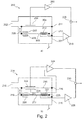
- Fig. 2a The embodiment depicted in Fig. 2a is very similar to the embodiment shown in Fig. 1a . However, in the embodiment depicted in Fig. 2a signals from both the electrode 208 and the inductor 212 are used to detect and monitor the movements of the membrane 204. As previously mentioned capacitance changes are measured via the electrode 208.
- the electrode 208 may be slightly angled/titled in order to follow the surface of the membrane 204 when it is in a displaced position.
- the upper portion therefore may be considered an electrode so that a capacitance is formed between the membrane 204 and the upper portion of the inductor 212.
- the membrane 204 is connected to ground via point 211 whereas the inductor 212 is biased.
- the signal from the electrode 208 is passed through pre-amp 209, whereas the signal from the inductor 212 is passed through pre-amp 213.
- the signals from the respective pre-amps 209, 213 are subtracted at point 229 prior to being processed even further if required.
- the embodiment depicted in Fig. 2a comprises a grounded housing 201 having a sound outlet 202, a membrane 204 suspended or fixated at 211, a moving armature 203 mechanically hinged at 210, two permanent magnets 206, 207 and a rigid connection 205 between the moving armature 203 and the membrane 204.
- the embodiment depicted in Fig. 2b is very similar to the embodiment shown in Fig. 1b .
- the embodiment depicted in Fig. 2b uses the signals from the electrodes 222, 223 and the inductor 227 to detect and monitor the movements of the membrane 218.
- changes of three capacitances are utilized in this embodiment.
- Fig. 2b the signals from the electrodes 222, 223 are passed through differential amplifier 224, whereas the signal from the inductor 227 is passed through pre-amp 228.
- the upper portion of the inductor 227 acts as an electrode so that a capacitance is formed between the membrane 218 and the upper portion of the inductor 227.
- the membrane 218 in Fig. 2b is connected to ground via point 226 whereas the inductor 227 is biased.
- the embodiment depicted in Fig. 2b comprises a grounded housing 215 having a sound outlet 216, a membrane 218 suspended or fixated at 226, a moving armature 217 mechanically hinged at 225, two permanent magnets 220, 221 and a rigid connection 219 between the moving armature 217 and the membrane 218.
- the electrodes 222, 223 are slightly and oppositely angled/titled in order to follow the surface of the membrane 218 when it is in a displaced position.
- Fig. 3 depicts an embodiment where only capacitance changes between the membrane 304 and the upper portion of the inductor 310 are used to detect and monitor the movements of the membrane 304. Similar to the previous embodiments the upper portion of the inductor 310 may be considered an electrode which forms a capacitor in combination with the membrane 304. Thus, the principle depicted in Fig. 3 may be applied to standard receivers as no changes are to be made to such standard receiver. In the embodiment depicted in Fig. 3 the inductor 310 is biased with up to 20 V in case the receiver is manufactured as a MEMS device. The signal from the inductor 310 is passed through the pre-amp 311 prior to being processed further. Similar to the previous embodiments, the embodiment depicted in Fig.
- FIG. 3 comprises a grounded housing 301 having a sound outlet 302, a membrane 304 suspended or fixated at 309, a moving armature 303 mechanically hinged at 308, two permanent magnets 306, 307 and a rigid connection 305 between the moving armature 303 and the membrane 304.
- Fig. 4 depicts an embodiment where a sensor 408, such as an accelerometer, is attached to the membrane 404 in order to detect and monitor the movements thereof.
- the signal from the sensor 408 is communicated to external equipment via a wireless transmission link.
- a wired connection can be used as well.
- the embodiment depicted in Fig. 4 comprises a grounded housing 401 having a sound outlet 402, a membrane 404 suspended or fixated at 410, a moving armature 403 mechanically hinged at 409, two permanent magnets 406, 407 and a rigid connection 405 between the moving armature 403 and the membrane 404.
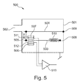
- Fig. 5 depicts an embodiment where only capacitance changes between shock plates 511, 512 are used to detect and monitor the movements of the membrane 504.
- the shock plates 511, 512 which are secured to respective permanent magnets 507, 506, are provided for limiting the movements of the moving armature 503 and they may be manufactured by a suitable metal or alternatively, as a laminated structure of for example plastic and metal, where the metal is biased. As the moving armature 503 moves up and down due to corresponding movements of the membrane 504 the capacitance between the shock plates 511, 512 will change. If the biased shock plates 511, 512 are connected to a differential amplifier 513 the movements of the membrane 504 monitored. The signal from the differential amplifier 513 may be passed on for further processing.
- the embodiment depicted in Fig. 5 comprises a grounded housing 501 having a sound outlet 502, a membrane 504 suspended or fixated at point 509, a moving armature 503 mechanically hinged at 508, two permanent magnets 506, 507, an inductor 510 and a rigid connection 505 between the moving armature 503 and the membrane 504.
Landscapes
- Engineering & Computer Science (AREA)
- Physics & Mathematics (AREA)
- Acoustics & Sound (AREA)
- Signal Processing (AREA)
- Health & Medical Sciences (AREA)
- General Health & Medical Sciences (AREA)
- Otolaryngology (AREA)
- Computer Networks & Wireless Communication (AREA)
- General Physics & Mathematics (AREA)
- Neurosurgery (AREA)
- Power Engineering (AREA)
- Measurement Of The Respiration, Hearing Ability, Form, And Blood Characteristics Of Living Organisms (AREA)
- Telephone Set Structure (AREA)
- Electrostatic, Electromagnetic, Magneto- Strictive, And Variable-Resistance Transducers (AREA)
Priority Applications (4)
| Application Number | Priority Date | Filing Date | Title |
|---|---|---|---|
| DK16188330.1T DK3293985T3 (da) | 2016-09-12 | 2016-09-12 | Lydgiver med integreret detektering af membranbevægelse |
| EP20215607.1A EP3826326A1 (de) | 2016-09-12 | 2016-09-12 | Empfänger mit integrierter membranbewegungsdetektion |
| EP16188330.1A EP3293985B1 (de) | 2016-09-12 | 2016-09-12 | Hörer mit integrierter membranbewegungserkennung |
| US15/697,965 US11070921B2 (en) | 2016-09-12 | 2017-09-07 | Receiver with integrated membrane movement detection |
Applications Claiming Priority (1)
| Application Number | Priority Date | Filing Date | Title |
|---|---|---|---|
| EP16188330.1A EP3293985B1 (de) | 2016-09-12 | 2016-09-12 | Hörer mit integrierter membranbewegungserkennung |
Related Child Applications (2)
| Application Number | Title | Priority Date | Filing Date |
|---|---|---|---|
| EP20215607.1A Division EP3826326A1 (de) | 2016-09-12 | 2016-09-12 | Empfänger mit integrierter membranbewegungsdetektion |
| EP20215607.1A Division-Into EP3826326A1 (de) | 2016-09-12 | 2016-09-12 | Empfänger mit integrierter membranbewegungsdetektion |
Publications (2)
| Publication Number | Publication Date |
|---|---|
| EP3293985A1 true EP3293985A1 (de) | 2018-03-14 |
| EP3293985B1 EP3293985B1 (de) | 2021-03-24 |
Family
ID=56896458
Family Applications (2)
| Application Number | Title | Priority Date | Filing Date |
|---|---|---|---|
| EP16188330.1A Active EP3293985B1 (de) | 2016-09-12 | 2016-09-12 | Hörer mit integrierter membranbewegungserkennung |
| EP20215607.1A Withdrawn EP3826326A1 (de) | 2016-09-12 | 2016-09-12 | Empfänger mit integrierter membranbewegungsdetektion |
Family Applications After (1)
| Application Number | Title | Priority Date | Filing Date |
|---|---|---|---|
| EP20215607.1A Withdrawn EP3826326A1 (de) | 2016-09-12 | 2016-09-12 | Empfänger mit integrierter membranbewegungsdetektion |
Country Status (3)
| Country | Link |
|---|---|
| US (1) | US11070921B2 (de) |
| EP (2) | EP3293985B1 (de) |
| DK (1) | DK3293985T3 (de) |
Citations (5)
| Publication number | Priority date | Publication date | Assignee | Title |
|---|---|---|---|---|
| WO2000027166A2 (en) * | 1998-11-02 | 2000-05-11 | Sarnoff Corporation | Transducer concepts for hearing aids and other devices |
| EP1353531A2 (de) * | 2002-04-09 | 2003-10-15 | Sonionmicrotronic Nederland B.V. | Akustischer Wandler mit reduzierter Dicke |
| EP2046072A2 (de) * | 2007-10-01 | 2009-04-08 | Sonion Nederland B.V. | Mikrofonanordnung mit Ersatzteil |
| US20110299692A1 (en) | 2009-01-23 | 2011-12-08 | Widex A/S | System, method and hearing aids for in situ occlusion effect measurement |
| US8831260B2 (en) * | 2008-03-31 | 2014-09-09 | Cochlear Limited | Bone conduction hearing device having acoustic feedback reduction system |
Family Cites Families (79)
| Publication number | Priority date | Publication date | Assignee | Title |
|---|---|---|---|---|
| NL1009544C2 (nl) | 1998-07-02 | 2000-01-10 | Microtronic Nederland Bv | Stelsel bestaande uit een microfoon en een voorversterker. |
| PL346751A1 (en) | 1998-09-24 | 2002-02-25 | Microtronic As | A hearing aid adapted for discrete operation |
| NL1011733C1 (nl) | 1999-04-06 | 2000-10-09 | Microtronic Nederland Bv | Elektroakoestische transducent met een membraan en werkwijze voor het bevestigen van een membraan in een dergelijke transducent. |
| US7706561B2 (en) | 1999-04-06 | 2010-04-27 | Sonion Nederland B.V. | Electroacoustic transducer with a diaphragm and method for fixing a diaphragm in such transducer |
| NL1011778C1 (nl) | 1999-04-13 | 2000-10-16 | Microtronic Nederland Bv | Microfoon voor een hoorapparaat en een hoorapparaat voorzien van een dergelijke microfoon. |
| JP2003502795A (ja) | 1999-06-10 | 2003-01-21 | テクトロニック・アクティーゼルスカブ | エンコーダ |
| US6522762B1 (en) | 1999-09-07 | 2003-02-18 | Microtronic A/S | Silicon-based sensor system |
| DE60128808T2 (de) | 2000-06-30 | 2008-02-07 | Sonion Nederland B.V. | Ein mikrofonzusammenbau |
| US7181035B2 (en) | 2000-11-22 | 2007-02-20 | Sonion Nederland B.V. | Acoustical receiver housing for hearing aids |
| TW510139B (en) | 2001-01-26 | 2002-11-11 | Kirk Acoustics As | An electroacoustic transducer and a coil and a magnet circuit therefor |
| US6831577B1 (en) | 2001-02-02 | 2004-12-14 | Sonion A/S | Sigma delta modulator having enlarged dynamic range due to stabilized signal swing |
| AU2002237204A1 (en) | 2001-03-09 | 2002-09-24 | Techtronic A/S | An electret condensor microphone preamplifier that is insensitive to leakage currents at the input |
| EP1248496A3 (de) | 2001-04-04 | 2005-11-02 | Sonionmicrotronic Nederland B.V. | Akustischer Empfänger mit verbesserter mechanischer Aufhängung |
| US7136496B2 (en) | 2001-04-18 | 2006-11-14 | Sonion Nederland B.V. | Electret assembly for a microphone having a backplate with improved charge stability |
| US7062058B2 (en) | 2001-04-18 | 2006-06-13 | Sonion Nederland B.V. | Cylindrical microphone having an electret assembly in the end cover |
| US6859542B2 (en) | 2001-05-31 | 2005-02-22 | Sonion Lyngby A/S | Method of providing a hydrophobic layer and a condenser microphone having such a layer |
| US7227968B2 (en) | 2001-06-25 | 2007-06-05 | Sonion Roskilde A/S | Expandsible Receiver Module |
| US6853290B2 (en) | 2001-07-20 | 2005-02-08 | Sonion Roskilde A/S | Switch/volume control assembly |
| US6788796B1 (en) | 2001-08-01 | 2004-09-07 | The Research Foundation Of The State University Of New York | Differential microphone |
| US7239714B2 (en) | 2001-10-09 | 2007-07-03 | Sonion Nederland B.V. | Microphone having a flexible printed circuit board for mounting components |
| CN100524568C (zh) | 2001-10-10 | 2009-08-05 | 桑尼昂微电子公司 | 数字脉冲发生器装置及包括该装置的移动装置 |
| WO2003032345A1 (en) | 2001-10-10 | 2003-04-17 | Sonionmicrotronic A/S | A multifunctional switch |
| WO2003047309A1 (en) | 2001-11-30 | 2003-06-05 | Sonion A/S | A high efficiency driver for miniature loudspeakers |
| KR20040081470A (ko) | 2002-01-25 | 2004-09-21 | 소니온 호르젠스 에이/에스 | 집적된 코일을 구비한 플랙서블 다이어프램 |
| DE10228157B3 (de) * | 2002-06-24 | 2004-01-08 | Siemens Audiologische Technik Gmbh | Hörgerätesystem mit einem Hörgerät und einer externen Prozessoreinheit |
| US6888408B2 (en) | 2002-08-27 | 2005-05-03 | Sonion Tech A/S | Preamplifier for two terminal electret condenser microphones |
| US7072482B2 (en) | 2002-09-06 | 2006-07-04 | Sonion Nederland B.V. | Microphone with improved sound inlet port |
| AU2002951326A0 (en) * | 2002-09-11 | 2002-09-26 | Innotech Pty Ltd | Communication apparatus and helmet |
| US8280082B2 (en) | 2002-10-08 | 2012-10-02 | Sonion Nederland B.V. | Electret assembly for a microphone having a backplate with improved charge stability |
| US7292876B2 (en) | 2002-10-08 | 2007-11-06 | Sonion Nederland B.V. | Digital system bus for use in low power instruments such as hearing aids and listening devices |
| US7142682B2 (en) | 2002-12-20 | 2006-11-28 | Sonion Mems A/S | Silicon-based transducer for use in hearing instruments and listening devices |
| ATE394020T1 (de) | 2002-12-23 | 2008-05-15 | Sonion Roskilde As | Eingekapselter hörer mit einem expandierbaren mittel wie z.b. einem ballon |
| US7008271B2 (en) | 2003-02-20 | 2006-03-07 | Sonion Roskilde A/S | Female connector assembly with a displaceable conductor |
| EP1455370B1 (de) | 2003-03-04 | 2006-06-07 | Sonion Roskilde A/S | Kombinierter Roller und Tastschalter |
| US7466835B2 (en) | 2003-03-18 | 2008-12-16 | Sonion A/S | Miniature microphone with balanced termination |
| DE10316287B3 (de) | 2003-04-09 | 2004-07-15 | Siemens Audiologische Technik Gmbh | Richtmikrofon |
| EP1473970B1 (de) | 2003-05-01 | 2008-07-16 | Sonion Roskilde A/S | Einsatzmodul für Miniatur-Hörhilfegerät |
| US7012200B2 (en) | 2004-02-13 | 2006-03-14 | Sonion Roskilde A/S | Integrated volume control and switch assembly |
| EP1757161B1 (de) | 2004-05-14 | 2016-11-30 | Sonion Nederland B.V. | Elektroakustischer wandler mit doppelter membran |
| EP1599067B1 (de) | 2004-05-21 | 2013-05-01 | Epcos Pte Ltd | Detektion und Kontrolle des Membrankollaps in einem Kondensatormikrofon |
| EP1613125A3 (de) | 2004-07-02 | 2008-10-22 | Sonion Nederland B.V. | Mikrofonaufbau mit magnetisch aktivierbarem Element zur Signal-Umschaltung und Fieldsanzeige |
| US7460681B2 (en) | 2004-07-20 | 2008-12-02 | Sonion Nederland B.V. | Radio frequency shielding for receivers within hearing aids and listening devices |
| EP1626612A3 (de) | 2004-08-11 | 2009-05-06 | Sonion Nederland B.V. | Montagestruktur eines Hörhilfegerätsmikrofons und Montageverfahren dafür |
| EP1638366B1 (de) | 2004-09-20 | 2015-08-26 | Sonion Nederland B.V. | Mikrofonanordnung |
| US7415121B2 (en) | 2004-10-29 | 2008-08-19 | Sonion Nederland B.V. | Microphone with internal damping |
| US8379899B2 (en) | 2004-11-01 | 2013-02-19 | Sonion Nederland B.V. | Electro-acoustical transducer and a transducer assembly |
| EP1853091B9 (de) | 2005-01-10 | 2012-02-15 | Sonion Nederland B.V. | Hörgerät mit Miniaturlautsprecher |
| EP1742506B1 (de) | 2005-07-06 | 2013-05-22 | Epcos Pte Ltd | Mikrofonanordnung mit P-typ Vorverstärkerseingangsstufe |
| US7899203B2 (en) | 2005-09-15 | 2011-03-01 | Sonion Nederland B.V. | Transducers with improved viscous damping |
| ATE462276T1 (de) | 2006-01-26 | 2010-04-15 | Sonion Mems As | Elastomerschild für miniaturmikrofone |
| EP1852882A3 (de) | 2006-05-01 | 2009-07-29 | Sonion Roskilde A/S | Multifunktionale Steuerung |
| US8170249B2 (en) | 2006-06-19 | 2012-05-01 | Sonion Nederland B.V. | Hearing aid having two receivers each amplifying a different frequency range |
| DK1895811T3 (en) | 2006-08-28 | 2016-08-29 | Sonion Nederland Bv | Several speakers with a common acoustic tube |
| ATE530033T1 (de) | 2006-11-21 | 2011-11-15 | Sonion As | Zweiteilige steckverbinderbaugruppe |
| DE112007003083B4 (de) | 2006-12-22 | 2019-05-09 | Tdk Corp. | Mikrofonbaugruppe mit Unterfüllmittel mit niedrigem Wärmeausdehnungskoeffizienten |
| EP1962551B1 (de) | 2007-02-20 | 2014-04-16 | Sonion Nederland B.V. | Empfänger mit beweglicher Armatur |
| US8391534B2 (en) | 2008-07-23 | 2013-03-05 | Asius Technologies, Llc | Inflatable ear device |
| US8160290B2 (en) | 2007-09-04 | 2012-04-17 | Sonion A/S | Electroacoustic transducer having a slotted terminal structure for connection to a flexible wire, and an assembly of the same |
| EP2071866B1 (de) | 2007-12-14 | 2017-04-19 | Sonion A/S | Abnehmbares Hörgerät mit Federbetrieb |
| US8189804B2 (en) | 2007-12-19 | 2012-05-29 | Sonion Nederland B.V. | Sound provider adapter to cancel out noise |
| DK2107828T3 (en) | 2008-04-02 | 2016-08-29 | Sonion Nederland Bv | Interior with a sound sensor and two sound detectors |
| US8101876B2 (en) | 2008-04-22 | 2012-01-24 | Sonion Aps | Electro-mechanical pulse generator |
| US8331595B2 (en) | 2008-06-11 | 2012-12-11 | Sonion Nederland Bv | Hearing instrument with improved venting and miniature loudspeaker therefore |
| US8509468B2 (en) | 2008-09-18 | 2013-08-13 | Sonion Nederland Bv | Apparatus for outputting sound comprising multiple receivers and a common output channel |
| US8526651B2 (en) | 2010-01-25 | 2013-09-03 | Sonion Nederland Bv | Receiver module for inflating a membrane in an ear device |
| US8313336B2 (en) | 2010-02-01 | 2012-11-20 | Sonion A/S | Assembly comprising a male and a female plug member, a male plug member and a female plug member |
| US7946890B1 (en) | 2010-02-02 | 2011-05-24 | Sonion A/S | Adapter for an electronic assembly |
| DK2393312T3 (da) | 2010-06-07 | 2014-10-27 | Sonion As | Fremgangsmåde til dannelse af en stikforbindelse til et høreapparat |
| EP2393311A1 (de) | 2010-06-07 | 2011-12-07 | Sonion A/S | Cerumenfilter für Hörgeräte |
| DK2408221T3 (en) | 2010-07-16 | 2017-01-16 | Sonion Nederland Bv | Hearing aid |
| US8712084B2 (en) | 2010-12-07 | 2014-04-29 | Sonion Nederland Bv | Motor assembly |
| EP2466915B1 (de) * | 2010-12-14 | 2016-03-23 | Sonion Nederland B.V. | Mehrschichtige Armatur für einen Lautsprecher mit beweglicher Armatur |
| DK2469705T3 (en) | 2010-12-21 | 2016-03-07 | Sonion Nederland Bv | Generating a supply voltage from the output of a class-D amplifier |
| EP2503792B1 (de) | 2011-03-21 | 2018-05-16 | Sonion Nederland B.V. | Lautsprecher mit beweglichem Anker mit Vibrationsunterdrückung |
| US9283376B2 (en) * | 2011-05-27 | 2016-03-15 | Cochlear Limited | Interaural time difference enhancement strategy |
| EP2552128A1 (de) | 2011-07-29 | 2013-01-30 | Sonion Nederland B.V. | Doppelkapsel-Richtmikrofon |
| US9055380B2 (en) | 2011-11-28 | 2015-06-09 | Sonion Nederland B.V. | Method for producing a tube for a hearing aid |
| EP2608576B1 (de) | 2011-12-21 | 2020-02-26 | Sonion Nederland B.V. | Vorrichtung und Verfahren zur Bereitstellung von Tönen |
| US8971554B2 (en) | 2011-12-22 | 2015-03-03 | Sonion Nederland Bv | Hearing aid with a sensor for changing power state of the hearing aid |
-
2016
- 2016-09-12 EP EP16188330.1A patent/EP3293985B1/de active Active
- 2016-09-12 EP EP20215607.1A patent/EP3826326A1/de not_active Withdrawn
- 2016-09-12 DK DK16188330.1T patent/DK3293985T3/da active
-
2017
- 2017-09-07 US US15/697,965 patent/US11070921B2/en active Active
Patent Citations (5)
| Publication number | Priority date | Publication date | Assignee | Title |
|---|---|---|---|---|
| WO2000027166A2 (en) * | 1998-11-02 | 2000-05-11 | Sarnoff Corporation | Transducer concepts for hearing aids and other devices |
| EP1353531A2 (de) * | 2002-04-09 | 2003-10-15 | Sonionmicrotronic Nederland B.V. | Akustischer Wandler mit reduzierter Dicke |
| EP2046072A2 (de) * | 2007-10-01 | 2009-04-08 | Sonion Nederland B.V. | Mikrofonanordnung mit Ersatzteil |
| US8831260B2 (en) * | 2008-03-31 | 2014-09-09 | Cochlear Limited | Bone conduction hearing device having acoustic feedback reduction system |
| US20110299692A1 (en) | 2009-01-23 | 2011-12-08 | Widex A/S | System, method and hearing aids for in situ occlusion effect measurement |
Also Published As
| Publication number | Publication date |
|---|---|
| EP3826326A1 (de) | 2021-05-26 |
| EP3293985B1 (de) | 2021-03-24 |
| DK3293985T3 (da) | 2021-06-21 |
| US20180077501A1 (en) | 2018-03-15 |
| US11070921B2 (en) | 2021-07-20 |
Similar Documents
| Publication | Publication Date | Title |
|---|---|---|
| US11743629B2 (en) | Hearing protection devices, speakers and noise exposure sensors therefore, and sensor housings and associated methods for the same | |
| US7245734B2 (en) | Directional microphone | |
| KR20170132180A (ko) | 듀얼 다이어프램 마이크로폰 | |
| US20110123052A1 (en) | Microphone | |
| JP5872687B2 (ja) | アナログデータ処理ユニットを備えるアセンブリ及び当該アセンブリを使用する方法 | |
| JP2009284110A (ja) | 音声入力装置及びその製造方法、並びに、情報処理システム | |
| JP5166117B2 (ja) | 音声入力装置及びその製造方法、並びに、情報処理システム | |
| WO2008062848A1 (en) | Voice input device, its manufacturing method and information processing system | |
| CN110907029A (zh) | 振动感测装置的校准方法 | |
| CN204669605U (zh) | 声学设备 | |
| US11070921B2 (en) | Receiver with integrated membrane movement detection | |
| JP6618230B1 (ja) | ピックアップセンサ及び骨伝導スピーカ | |
| JP4212635B1 (ja) | 音声入力装置及びその製造方法、並びに、情報処理システム | |
| US20240064474A1 (en) | Sound and vibration sensor | |
| JP5097511B2 (ja) | 音声入力装置及びその製造方法、並びに、情報処理システム | |
| JP2859844B2 (ja) | マイクロホン | |
| CN116601975A (zh) | 用于换能器的可移动元件、换能器、入耳式设备和用于确定换能器中的状况发生的方法 | |
| CN118471256A (zh) | 超声信号的检测 |
Legal Events
| Date | Code | Title | Description |
|---|---|---|---|
| PUAI | Public reference made under article 153(3) epc to a published international application that has entered the european phase |
Free format text: ORIGINAL CODE: 0009012 |
|
| STAA | Information on the status of an ep patent application or granted ep patent |
Free format text: STATUS: THE APPLICATION HAS BEEN PUBLISHED |
|
| AK | Designated contracting states |
Kind code of ref document: A1 Designated state(s): AL AT BE BG CH CY CZ DE DK EE ES FI FR GB GR HR HU IE IS IT LI LT LU LV MC MK MT NL NO PL PT RO RS SE SI SK SM TR |
|
| AX | Request for extension of the european patent |
Extension state: BA ME |
|
| STAA | Information on the status of an ep patent application or granted ep patent |
Free format text: STATUS: REQUEST FOR EXAMINATION WAS MADE |
|
| 17P | Request for examination filed |
Effective date: 20180914 |
|
| RBV | Designated contracting states (corrected) |
Designated state(s): AL AT BE BG CH CY CZ DE DK EE ES FI FR GB GR HR HU IE IS IT LI LT LU LV MC MK MT NL NO PL PT RO RS SE SI SK SM TR |
|
| STAA | Information on the status of an ep patent application or granted ep patent |
Free format text: STATUS: EXAMINATION IS IN PROGRESS |
|
| 17Q | First examination report despatched |
Effective date: 20190416 |
|
| GRAP | Despatch of communication of intention to grant a patent |
Free format text: ORIGINAL CODE: EPIDOSNIGR1 |
|
| STAA | Information on the status of an ep patent application or granted ep patent |
Free format text: STATUS: GRANT OF PATENT IS INTENDED |
|
| RIC1 | Information provided on ipc code assigned before grant |
Ipc: H04R 25/00 20060101ALN20201022BHEP Ipc: H04R 19/01 20060101ALN20201022BHEP Ipc: H04R 19/04 20060101AFI20201022BHEP Ipc: H04R 11/02 20060101ALN20201022BHEP |
|
| INTG | Intention to grant announced |
Effective date: 20201123 |
|
| GRAS | Grant fee paid |
Free format text: ORIGINAL CODE: EPIDOSNIGR3 |
|
| GRAA | (expected) grant |
Free format text: ORIGINAL CODE: 0009210 |
|
| STAA | Information on the status of an ep patent application or granted ep patent |
Free format text: STATUS: THE PATENT HAS BEEN GRANTED |
|
| AK | Designated contracting states |
Kind code of ref document: B1 Designated state(s): AL AT BE BG CH CY CZ DE DK EE ES FI FR GB GR HR HU IE IS IT LI LT LU LV MC MK MT NL NO PL PT RO RS SE SI SK SM TR |
|
| REG | Reference to a national code |
Ref country code: GB Ref legal event code: FG4D |
|
| REG | Reference to a national code |
Ref country code: CH Ref legal event code: EP |
|
| REG | Reference to a national code |
Ref country code: IE Ref legal event code: FG4D |
|
| REG | Reference to a national code |
Ref country code: AT Ref legal event code: REF Ref document number: 1375728 Country of ref document: AT Kind code of ref document: T Effective date: 20210415 Ref country code: DE Ref legal event code: R096 Ref document number: 602016054724 Country of ref document: DE |
|
| REG | Reference to a national code |
Ref country code: DK Ref legal event code: T3 Effective date: 20210618 |
|
| REG | Reference to a national code |
Ref country code: LT Ref legal event code: MG9D |
|
| PG25 | Lapsed in a contracting state [announced via postgrant information from national office to epo] |
Ref country code: NO Free format text: LAPSE BECAUSE OF FAILURE TO SUBMIT A TRANSLATION OF THE DESCRIPTION OR TO PAY THE FEE WITHIN THE PRESCRIBED TIME-LIMIT Effective date: 20210624 Ref country code: HR Free format text: LAPSE BECAUSE OF FAILURE TO SUBMIT A TRANSLATION OF THE DESCRIPTION OR TO PAY THE FEE WITHIN THE PRESCRIBED TIME-LIMIT Effective date: 20210324 Ref country code: GR Free format text: LAPSE BECAUSE OF FAILURE TO SUBMIT A TRANSLATION OF THE DESCRIPTION OR TO PAY THE FEE WITHIN THE PRESCRIBED TIME-LIMIT Effective date: 20210625 Ref country code: FI Free format text: LAPSE BECAUSE OF FAILURE TO SUBMIT A TRANSLATION OF THE DESCRIPTION OR TO PAY THE FEE WITHIN THE PRESCRIBED TIME-LIMIT Effective date: 20210324 Ref country code: BG Free format text: LAPSE BECAUSE OF FAILURE TO SUBMIT A TRANSLATION OF THE DESCRIPTION OR TO PAY THE FEE WITHIN THE PRESCRIBED TIME-LIMIT Effective date: 20210624 |
|
| PG25 | Lapsed in a contracting state [announced via postgrant information from national office to epo] |
Ref country code: SE Free format text: LAPSE BECAUSE OF FAILURE TO SUBMIT A TRANSLATION OF THE DESCRIPTION OR TO PAY THE FEE WITHIN THE PRESCRIBED TIME-LIMIT Effective date: 20210324 Ref country code: RS Free format text: LAPSE BECAUSE OF FAILURE TO SUBMIT A TRANSLATION OF THE DESCRIPTION OR TO PAY THE FEE WITHIN THE PRESCRIBED TIME-LIMIT Effective date: 20210324 Ref country code: LV Free format text: LAPSE BECAUSE OF FAILURE TO SUBMIT A TRANSLATION OF THE DESCRIPTION OR TO PAY THE FEE WITHIN THE PRESCRIBED TIME-LIMIT Effective date: 20210324 |
|
| REG | Reference to a national code |
Ref country code: NL Ref legal event code: MP Effective date: 20210324 |
|
| REG | Reference to a national code |
Ref country code: AT Ref legal event code: MK05 Ref document number: 1375728 Country of ref document: AT Kind code of ref document: T Effective date: 20210324 |
|
| PG25 | Lapsed in a contracting state [announced via postgrant information from national office to epo] |
Ref country code: NL Free format text: LAPSE BECAUSE OF FAILURE TO SUBMIT A TRANSLATION OF THE DESCRIPTION OR TO PAY THE FEE WITHIN THE PRESCRIBED TIME-LIMIT Effective date: 20210324 |
|
| PG25 | Lapsed in a contracting state [announced via postgrant information from national office to epo] |
Ref country code: EE Free format text: LAPSE BECAUSE OF FAILURE TO SUBMIT A TRANSLATION OF THE DESCRIPTION OR TO PAY THE FEE WITHIN THE PRESCRIBED TIME-LIMIT Effective date: 20210324 Ref country code: CZ Free format text: LAPSE BECAUSE OF FAILURE TO SUBMIT A TRANSLATION OF THE DESCRIPTION OR TO PAY THE FEE WITHIN THE PRESCRIBED TIME-LIMIT Effective date: 20210324 Ref country code: LT Free format text: LAPSE BECAUSE OF FAILURE TO SUBMIT A TRANSLATION OF THE DESCRIPTION OR TO PAY THE FEE WITHIN THE PRESCRIBED TIME-LIMIT Effective date: 20210324 Ref country code: AT Free format text: LAPSE BECAUSE OF FAILURE TO SUBMIT A TRANSLATION OF THE DESCRIPTION OR TO PAY THE FEE WITHIN THE PRESCRIBED TIME-LIMIT Effective date: 20210324 Ref country code: SM Free format text: LAPSE BECAUSE OF FAILURE TO SUBMIT A TRANSLATION OF THE DESCRIPTION OR TO PAY THE FEE WITHIN THE PRESCRIBED TIME-LIMIT Effective date: 20210324 |
|
| PG25 | Lapsed in a contracting state [announced via postgrant information from national office to epo] |
Ref country code: PT Free format text: LAPSE BECAUSE OF FAILURE TO SUBMIT A TRANSLATION OF THE DESCRIPTION OR TO PAY THE FEE WITHIN THE PRESCRIBED TIME-LIMIT Effective date: 20210726 Ref country code: PL Free format text: LAPSE BECAUSE OF FAILURE TO SUBMIT A TRANSLATION OF THE DESCRIPTION OR TO PAY THE FEE WITHIN THE PRESCRIBED TIME-LIMIT Effective date: 20210324 Ref country code: SK Free format text: LAPSE BECAUSE OF FAILURE TO SUBMIT A TRANSLATION OF THE DESCRIPTION OR TO PAY THE FEE WITHIN THE PRESCRIBED TIME-LIMIT Effective date: 20210324 Ref country code: RO Free format text: LAPSE BECAUSE OF FAILURE TO SUBMIT A TRANSLATION OF THE DESCRIPTION OR TO PAY THE FEE WITHIN THE PRESCRIBED TIME-LIMIT Effective date: 20210324 Ref country code: IS Free format text: LAPSE BECAUSE OF FAILURE TO SUBMIT A TRANSLATION OF THE DESCRIPTION OR TO PAY THE FEE WITHIN THE PRESCRIBED TIME-LIMIT Effective date: 20210724 |
|
| REG | Reference to a national code |
Ref country code: DE Ref legal event code: R097 Ref document number: 602016054724 Country of ref document: DE |
|
| PG25 | Lapsed in a contracting state [announced via postgrant information from national office to epo] |
Ref country code: ES Free format text: LAPSE BECAUSE OF FAILURE TO SUBMIT A TRANSLATION OF THE DESCRIPTION OR TO PAY THE FEE WITHIN THE PRESCRIBED TIME-LIMIT Effective date: 20210324 Ref country code: AL Free format text: LAPSE BECAUSE OF FAILURE TO SUBMIT A TRANSLATION OF THE DESCRIPTION OR TO PAY THE FEE WITHIN THE PRESCRIBED TIME-LIMIT Effective date: 20210324 |
|
| PLBE | No opposition filed within time limit |
Free format text: ORIGINAL CODE: 0009261 |
|
| STAA | Information on the status of an ep patent application or granted ep patent |
Free format text: STATUS: NO OPPOSITION FILED WITHIN TIME LIMIT |
|
| PG25 | Lapsed in a contracting state [announced via postgrant information from national office to epo] |
Ref country code: SI Free format text: LAPSE BECAUSE OF FAILURE TO SUBMIT A TRANSLATION OF THE DESCRIPTION OR TO PAY THE FEE WITHIN THE PRESCRIBED TIME-LIMIT Effective date: 20210324 |
|
| 26N | No opposition filed |
Effective date: 20220104 |
|
| REG | Reference to a national code |
Ref country code: BE Ref legal event code: MM Effective date: 20210930 |
|
| PG25 | Lapsed in a contracting state [announced via postgrant information from national office to epo] |
Ref country code: IS Free format text: LAPSE BECAUSE OF FAILURE TO SUBMIT A TRANSLATION OF THE DESCRIPTION OR TO PAY THE FEE WITHIN THE PRESCRIBED TIME-LIMIT Effective date: 20210724 Ref country code: MC Free format text: LAPSE BECAUSE OF FAILURE TO SUBMIT A TRANSLATION OF THE DESCRIPTION OR TO PAY THE FEE WITHIN THE PRESCRIBED TIME-LIMIT Effective date: 20210324 |
|
| PG25 | Lapsed in a contracting state [announced via postgrant information from national office to epo] |
Ref country code: LU Free format text: LAPSE BECAUSE OF NON-PAYMENT OF DUE FEES Effective date: 20210912 Ref country code: IE Free format text: LAPSE BECAUSE OF NON-PAYMENT OF DUE FEES Effective date: 20210912 Ref country code: BE Free format text: LAPSE BECAUSE OF NON-PAYMENT OF DUE FEES Effective date: 20210930 |
|
| PGFP | Annual fee paid to national office [announced via postgrant information from national office to epo] |
Ref country code: GB Payment date: 20220804 Year of fee payment: 7 |
|
| PG25 | Lapsed in a contracting state [announced via postgrant information from national office to epo] |
Ref country code: IT Free format text: LAPSE BECAUSE OF FAILURE TO SUBMIT A TRANSLATION OF THE DESCRIPTION OR TO PAY THE FEE WITHIN THE PRESCRIBED TIME-LIMIT Effective date: 20210324 |
|
| PGFP | Annual fee paid to national office [announced via postgrant information from national office to epo] |
Ref country code: CH Payment date: 20221001 Year of fee payment: 7 |
|
| PG25 | Lapsed in a contracting state [announced via postgrant information from national office to epo] |
Ref country code: HU Free format text: LAPSE BECAUSE OF FAILURE TO SUBMIT A TRANSLATION OF THE DESCRIPTION OR TO PAY THE FEE WITHIN THE PRESCRIBED TIME-LIMIT; INVALID AB INITIO Effective date: 20160912 |
|
| PG25 | Lapsed in a contracting state [announced via postgrant information from national office to epo] |
Ref country code: CY Free format text: LAPSE BECAUSE OF FAILURE TO SUBMIT A TRANSLATION OF THE DESCRIPTION OR TO PAY THE FEE WITHIN THE PRESCRIBED TIME-LIMIT Effective date: 20210324 |
|
| PG25 | Lapsed in a contracting state [announced via postgrant information from national office to epo] |
Ref country code: MK Free format text: LAPSE BECAUSE OF FAILURE TO SUBMIT A TRANSLATION OF THE DESCRIPTION OR TO PAY THE FEE WITHIN THE PRESCRIBED TIME-LIMIT Effective date: 20210324 |
|
| REG | Reference to a national code |
Ref country code: CH Ref legal event code: PL |
|
| GBPC | Gb: european patent ceased through non-payment of renewal fee |
Effective date: 20230912 |
|
| PG25 | Lapsed in a contracting state [announced via postgrant information from national office to epo] |
Ref country code: GB Free format text: LAPSE BECAUSE OF NON-PAYMENT OF DUE FEES Effective date: 20230912 |
|
| PG25 | Lapsed in a contracting state [announced via postgrant information from national office to epo] |
Ref country code: CH Free format text: LAPSE BECAUSE OF NON-PAYMENT OF DUE FEES Effective date: 20230930 |
|
| PG25 | Lapsed in a contracting state [announced via postgrant information from national office to epo] |
Ref country code: GB Free format text: LAPSE BECAUSE OF NON-PAYMENT OF DUE FEES Effective date: 20230912 Ref country code: CH Free format text: LAPSE BECAUSE OF NON-PAYMENT OF DUE FEES Effective date: 20230930 |
|
| PG25 | Lapsed in a contracting state [announced via postgrant information from national office to epo] |
Ref country code: MT Free format text: LAPSE BECAUSE OF FAILURE TO SUBMIT A TRANSLATION OF THE DESCRIPTION OR TO PAY THE FEE WITHIN THE PRESCRIBED TIME-LIMIT Effective date: 20210324 |
|
| PGFP | Annual fee paid to national office [announced via postgrant information from national office to epo] |
Ref country code: DK Payment date: 20240913 Year of fee payment: 9 |
|
| PGFP | Annual fee paid to national office [announced via postgrant information from national office to epo] |
Ref country code: FR Payment date: 20240821 Year of fee payment: 9 |
|
| PGFP | Annual fee paid to national office [announced via postgrant information from national office to epo] |
Ref country code: DE Payment date: 20250919 Year of fee payment: 10 |
|
| PG25 | Lapsed in a contracting state [announced via postgrant information from national office to epo] |
Ref country code: TR Free format text: LAPSE BECAUSE OF FAILURE TO SUBMIT A TRANSLATION OF THE DESCRIPTION OR TO PAY THE FEE WITHIN THE PRESCRIBED TIME-LIMIT Effective date: 20210324 |
|
| REG | Reference to a national code |
Ref country code: DK Ref legal event code: EBP Effective date: 20250930 |