EP1354094B1 - Fils enroules en spirale pour garnitures de machine a papier et courroies industrielles - Google Patents
Fils enroules en spirale pour garnitures de machine a papier et courroies industrielles Download PDFInfo
- Publication number
- EP1354094B1 EP1354094B1 EP20020703245 EP02703245A EP1354094B1 EP 1354094 B1 EP1354094 B1 EP 1354094B1 EP 20020703245 EP20020703245 EP 20020703245 EP 02703245 A EP02703245 A EP 02703245A EP 1354094 B1 EP1354094 B1 EP 1354094B1
- Authority
- EP
- European Patent Office
- Prior art keywords
- monofilament yarn
- fabric
- monofilament
- yarn
- length
- Prior art date
- Legal status (The legal status is an assumption and is not a legal conclusion. Google has not performed a legal analysis and makes no representation as to the accuracy of the status listed.)
- Expired - Lifetime
Links
- 239000004744 fabric Substances 0.000 claims abstract description 137
- 239000000463 material Substances 0.000 claims abstract description 14
- 239000002952 polymeric resin Substances 0.000 claims abstract description 8
- 229920003002 synthetic resin Polymers 0.000 claims abstract description 8
- 230000003014 reinforcing effect Effects 0.000 claims abstract description 4
- 239000000853 adhesive Substances 0.000 claims description 22
- 230000001070 adhesive effect Effects 0.000 claims description 22
- 239000011800 void material Substances 0.000 claims description 15
- XLYOFNOQVPJJNP-UHFFFAOYSA-N water Substances O XLYOFNOQVPJJNP-UHFFFAOYSA-N 0.000 claims description 13
- 239000000835 fiber Substances 0.000 claims description 11
- 239000002657 fibrous material Substances 0.000 claims description 6
- 238000003860 storage Methods 0.000 claims description 6
- 229920002635 polyurethane Polymers 0.000 claims description 4
- 239000004814 polyurethane Substances 0.000 claims description 4
- 239000004952 Polyamide Substances 0.000 claims description 3
- 229920002647 polyamide Polymers 0.000 claims description 3
- 229920000728 polyester Polymers 0.000 claims description 3
- 229920001470 polyketone Polymers 0.000 claims description 3
- 229920005989 resin Polymers 0.000 claims description 3
- 239000011347 resin Substances 0.000 claims description 3
- 238000000034 method Methods 0.000 description 38
- 239000004831 Hot glue Substances 0.000 description 15
- 238000004519 manufacturing process Methods 0.000 description 11
- 238000004804 winding Methods 0.000 description 10
- 238000005304 joining Methods 0.000 description 7
- 239000002759 woven fabric Substances 0.000 description 6
- 210000002105 tongue Anatomy 0.000 description 5
- 238000001125 extrusion Methods 0.000 description 3
- 239000002002 slurry Substances 0.000 description 3
- 229920003043 Cellulose fiber Polymers 0.000 description 2
- 239000002761 deinking Substances 0.000 description 2
- 239000000289 melt material Substances 0.000 description 2
- 238000012986 modification Methods 0.000 description 2
- 230000004048 modification Effects 0.000 description 2
- 238000004080 punching Methods 0.000 description 2
- 238000010924 continuous production Methods 0.000 description 1
- 238000000151 deposition Methods 0.000 description 1
- 239000006185 dispersion Substances 0.000 description 1
- 230000008020 evaporation Effects 0.000 description 1
- 238000001704 evaporation Methods 0.000 description 1
- 238000003475 lamination Methods 0.000 description 1
- 230000035699 permeability Effects 0.000 description 1
- 238000003825 pressing Methods 0.000 description 1
- 239000010802 sludge Substances 0.000 description 1
- 239000000758 substrate Substances 0.000 description 1
- 239000002562 thickening agent Substances 0.000 description 1
Images

Classifications
-
- D—TEXTILES; PAPER
- D21—PAPER-MAKING; PRODUCTION OF CELLULOSE
- D21F—PAPER-MAKING MACHINES; METHODS OF PRODUCING PAPER THEREON
- D21F1/00—Wet end of machines for making continuous webs of paper
- D21F1/0027—Screen-cloths
- D21F1/0081—Screen-cloths with single endless strands travelling in generally parallel convolutions
-
- D—TEXTILES; PAPER
- D21—PAPER-MAKING; PRODUCTION OF CELLULOSE
- D21F—PAPER-MAKING MACHINES; METHODS OF PRODUCING PAPER THEREON
- D21F7/00—Other details of machines for making continuous webs of paper
- D21F7/08—Felts
-
- B—PERFORMING OPERATIONS; TRANSPORTING
- B29—WORKING OF PLASTICS; WORKING OF SUBSTANCES IN A PLASTIC STATE IN GENERAL
- B29C—SHAPING OR JOINING OF PLASTICS; SHAPING OF MATERIAL IN A PLASTIC STATE, NOT OTHERWISE PROVIDED FOR; AFTER-TREATMENT OF THE SHAPED PRODUCTS, e.g. REPAIRING
- B29C53/00—Shaping by bending, folding, twisting, straightening or flattening; Apparatus therefor
- B29C53/56—Winding and joining, e.g. winding spirally
- B29C53/58—Winding and joining, e.g. winding spirally helically
- B29C53/78—Winding and joining, e.g. winding spirally helically using profiled sheets or strips
-
- D—TEXTILES; PAPER
- D21—PAPER-MAKING; PRODUCTION OF CELLULOSE
- D21F—PAPER-MAKING MACHINES; METHODS OF PRODUCING PAPER THEREON
- D21F1/00—Wet end of machines for making continuous webs of paper
- D21F1/0027—Screen-cloths
-
- D—TEXTILES; PAPER
- D21—PAPER-MAKING; PRODUCTION OF CELLULOSE
- D21F—PAPER-MAKING MACHINES; METHODS OF PRODUCING PAPER THEREON
- D21F7/00—Other details of machines for making continuous webs of paper
- D21F7/08—Felts
- D21F7/083—Multi-layer felts
-
- Y—GENERAL TAGGING OF NEW TECHNOLOGICAL DEVELOPMENTS; GENERAL TAGGING OF CROSS-SECTIONAL TECHNOLOGIES SPANNING OVER SEVERAL SECTIONS OF THE IPC; TECHNICAL SUBJECTS COVERED BY FORMER USPC CROSS-REFERENCE ART COLLECTIONS [XRACs] AND DIGESTS
- Y10—TECHNICAL SUBJECTS COVERED BY FORMER USPC
- Y10S—TECHNICAL SUBJECTS COVERED BY FORMER USPC CROSS-REFERENCE ART COLLECTIONS [XRACs] AND DIGESTS
- Y10S162/00—Paper making and fiber liberation
- Y10S162/90—Papermaking press felts
-
- Y—GENERAL TAGGING OF NEW TECHNOLOGICAL DEVELOPMENTS; GENERAL TAGGING OF CROSS-SECTIONAL TECHNOLOGIES SPANNING OVER SEVERAL SECTIONS OF THE IPC; TECHNICAL SUBJECTS COVERED BY FORMER USPC CROSS-REFERENCE ART COLLECTIONS [XRACs] AND DIGESTS
- Y10—TECHNICAL SUBJECTS COVERED BY FORMER USPC
- Y10T—TECHNICAL SUBJECTS COVERED BY FORMER US CLASSIFICATION
- Y10T428/00—Stock material or miscellaneous articles
- Y10T428/19—Sheets or webs edge spliced or joined
- Y10T428/192—Sheets or webs coplanar
-
- Y—GENERAL TAGGING OF NEW TECHNOLOGICAL DEVELOPMENTS; GENERAL TAGGING OF CROSS-SECTIONAL TECHNOLOGIES SPANNING OVER SEVERAL SECTIONS OF THE IPC; TECHNICAL SUBJECTS COVERED BY FORMER USPC CROSS-REFERENCE ART COLLECTIONS [XRACs] AND DIGESTS
- Y10—TECHNICAL SUBJECTS COVERED BY FORMER USPC
- Y10T—TECHNICAL SUBJECTS COVERED BY FORMER US CLASSIFICATION
- Y10T428/00—Stock material or miscellaneous articles
- Y10T428/24—Structurally defined web or sheet [e.g., overall dimension, etc.]
- Y10T428/24273—Structurally defined web or sheet [e.g., overall dimension, etc.] including aperture
-
- Y—GENERAL TAGGING OF NEW TECHNOLOGICAL DEVELOPMENTS; GENERAL TAGGING OF CROSS-SECTIONAL TECHNOLOGIES SPANNING OVER SEVERAL SECTIONS OF THE IPC; TECHNICAL SUBJECTS COVERED BY FORMER USPC CROSS-REFERENCE ART COLLECTIONS [XRACs] AND DIGESTS
- Y10—TECHNICAL SUBJECTS COVERED BY FORMER USPC
- Y10T—TECHNICAL SUBJECTS COVERED BY FORMER US CLASSIFICATION
- Y10T428/00—Stock material or miscellaneous articles
- Y10T428/24—Structurally defined web or sheet [e.g., overall dimension, etc.]
- Y10T428/24479—Structurally defined web or sheet [e.g., overall dimension, etc.] including variation in thickness
- Y10T428/24521—Structurally defined web or sheet [e.g., overall dimension, etc.] including variation in thickness with component conforming to contour of nonplanar surface
- Y10T428/24537—Parallel ribs and/or grooves
-
- Y—GENERAL TAGGING OF NEW TECHNOLOGICAL DEVELOPMENTS; GENERAL TAGGING OF CROSS-SECTIONAL TECHNOLOGIES SPANNING OVER SEVERAL SECTIONS OF THE IPC; TECHNICAL SUBJECTS COVERED BY FORMER USPC CROSS-REFERENCE ART COLLECTIONS [XRACs] AND DIGESTS
- Y10—TECHNICAL SUBJECTS COVERED BY FORMER USPC
- Y10T—TECHNICAL SUBJECTS COVERED BY FORMER US CLASSIFICATION
- Y10T428/00—Stock material or miscellaneous articles
- Y10T428/249921—Web or sheet containing structurally defined element or component
- Y10T428/249923—Including interlaminar mechanical fastener
-
- Y—GENERAL TAGGING OF NEW TECHNOLOGICAL DEVELOPMENTS; GENERAL TAGGING OF CROSS-SECTIONAL TECHNOLOGIES SPANNING OVER SEVERAL SECTIONS OF THE IPC; TECHNICAL SUBJECTS COVERED BY FORMER USPC CROSS-REFERENCE ART COLLECTIONS [XRACs] AND DIGESTS
- Y10—TECHNICAL SUBJECTS COVERED BY FORMER USPC
- Y10T—TECHNICAL SUBJECTS COVERED BY FORMER US CLASSIFICATION
- Y10T428/00—Stock material or miscellaneous articles
- Y10T428/29—Coated or structually defined flake, particle, cell, strand, strand portion, rod, filament, macroscopic fiber or mass thereof
- Y10T428/2913—Rod, strand, filament or fiber
- Y10T428/2922—Nonlinear [e.g., crimped, coiled, etc.]
- Y10T428/2925—Helical or coiled
-
- Y—GENERAL TAGGING OF NEW TECHNOLOGICAL DEVELOPMENTS; GENERAL TAGGING OF CROSS-SECTIONAL TECHNOLOGIES SPANNING OVER SEVERAL SECTIONS OF THE IPC; TECHNICAL SUBJECTS COVERED BY FORMER USPC CROSS-REFERENCE ART COLLECTIONS [XRACs] AND DIGESTS
- Y10—TECHNICAL SUBJECTS COVERED BY FORMER USPC
- Y10T—TECHNICAL SUBJECTS COVERED BY FORMER US CLASSIFICATION
- Y10T428/00—Stock material or miscellaneous articles
- Y10T428/29—Coated or structually defined flake, particle, cell, strand, strand portion, rod, filament, macroscopic fiber or mass thereof
- Y10T428/2913—Rod, strand, filament or fiber
- Y10T428/2973—Particular cross section
-
- Y—GENERAL TAGGING OF NEW TECHNOLOGICAL DEVELOPMENTS; GENERAL TAGGING OF CROSS-SECTIONAL TECHNOLOGIES SPANNING OVER SEVERAL SECTIONS OF THE IPC; TECHNICAL SUBJECTS COVERED BY FORMER USPC CROSS-REFERENCE ART COLLECTIONS [XRACs] AND DIGESTS
- Y10—TECHNICAL SUBJECTS COVERED BY FORMER USPC
- Y10T—TECHNICAL SUBJECTS COVERED BY FORMER US CLASSIFICATION
- Y10T442/00—Fabric [woven, knitted, or nonwoven textile or cloth, etc.]
- Y10T442/30—Woven fabric [i.e., woven strand or strip material]
- Y10T442/3065—Including strand which is of specific structural definition
- Y10T442/3089—Cross-sectional configuration of strand material is specified
-
- Y—GENERAL TAGGING OF NEW TECHNOLOGICAL DEVELOPMENTS; GENERAL TAGGING OF CROSS-SECTIONAL TECHNOLOGIES SPANNING OVER SEVERAL SECTIONS OF THE IPC; TECHNICAL SUBJECTS COVERED BY FORMER USPC CROSS-REFERENCE ART COLLECTIONS [XRACs] AND DIGESTS
- Y10—TECHNICAL SUBJECTS COVERED BY FORMER USPC
- Y10T—TECHNICAL SUBJECTS COVERED BY FORMER US CLASSIFICATION
- Y10T442/00—Fabric [woven, knitted, or nonwoven textile or cloth, etc.]
- Y10T442/30—Woven fabric [i.e., woven strand or strip material]
- Y10T442/3065—Including strand which is of specific structural definition
- Y10T442/3089—Cross-sectional configuration of strand material is specified
- Y10T442/3114—Cross-sectional configuration of the strand material is other than circular
-
- Y—GENERAL TAGGING OF NEW TECHNOLOGICAL DEVELOPMENTS; GENERAL TAGGING OF CROSS-SECTIONAL TECHNOLOGIES SPANNING OVER SEVERAL SECTIONS OF THE IPC; TECHNICAL SUBJECTS COVERED BY FORMER USPC CROSS-REFERENCE ART COLLECTIONS [XRACs] AND DIGESTS
- Y10—TECHNICAL SUBJECTS COVERED BY FORMER USPC
- Y10T—TECHNICAL SUBJECTS COVERED BY FORMER US CLASSIFICATION
- Y10T442/00—Fabric [woven, knitted, or nonwoven textile or cloth, etc.]
- Y10T442/30—Woven fabric [i.e., woven strand or strip material]
- Y10T442/3472—Woven fabric including an additional woven fabric layer
- Y10T442/348—Mechanically needled or hydroentangled
-
- Y—GENERAL TAGGING OF NEW TECHNOLOGICAL DEVELOPMENTS; GENERAL TAGGING OF CROSS-SECTIONAL TECHNOLOGIES SPANNING OVER SEVERAL SECTIONS OF THE IPC; TECHNICAL SUBJECTS COVERED BY FORMER USPC CROSS-REFERENCE ART COLLECTIONS [XRACs] AND DIGESTS
- Y10—TECHNICAL SUBJECTS COVERED BY FORMER USPC
- Y10T—TECHNICAL SUBJECTS COVERED BY FORMER US CLASSIFICATION
- Y10T442/00—Fabric [woven, knitted, or nonwoven textile or cloth, etc.]
- Y10T442/60—Nonwoven fabric [i.e., nonwoven strand or fiber material]
- Y10T442/608—Including strand or fiber material which is of specific structural definition
- Y10T442/609—Cross-sectional configuration of strand or fiber material is specified
- Y10T442/611—Cross-sectional configuration of strand or fiber material is other than circular
-
- Y—GENERAL TAGGING OF NEW TECHNOLOGICAL DEVELOPMENTS; GENERAL TAGGING OF CROSS-SECTIONAL TECHNOLOGIES SPANNING OVER SEVERAL SECTIONS OF THE IPC; TECHNICAL SUBJECTS COVERED BY FORMER USPC CROSS-REFERENCE ART COLLECTIONS [XRACs] AND DIGESTS
- Y10—TECHNICAL SUBJECTS COVERED BY FORMER USPC
- Y10T—TECHNICAL SUBJECTS COVERED BY FORMER US CLASSIFICATION
- Y10T442/00—Fabric [woven, knitted, or nonwoven textile or cloth, etc.]
- Y10T442/60—Nonwoven fabric [i.e., nonwoven strand or fiber material]
- Y10T442/608—Including strand or fiber material which is of specific structural definition
- Y10T442/609—Cross-sectional configuration of strand or fiber material is specified
- Y10T442/612—Hollow strand or fiber material
-
- Y—GENERAL TAGGING OF NEW TECHNOLOGICAL DEVELOPMENTS; GENERAL TAGGING OF CROSS-SECTIONAL TECHNOLOGIES SPANNING OVER SEVERAL SECTIONS OF THE IPC; TECHNICAL SUBJECTS COVERED BY FORMER USPC CROSS-REFERENCE ART COLLECTIONS [XRACs] AND DIGESTS
- Y10—TECHNICAL SUBJECTS COVERED BY FORMER USPC
- Y10T—TECHNICAL SUBJECTS COVERED BY FORMER US CLASSIFICATION
- Y10T442/00—Fabric [woven, knitted, or nonwoven textile or cloth, etc.]
- Y10T442/60—Nonwoven fabric [i.e., nonwoven strand or fiber material]
- Y10T442/608—Including strand or fiber material which is of specific structural definition
- Y10T442/627—Strand or fiber material is specified as non-linear [e.g., crimped, coiled, etc.]
Definitions
- the present invention relates to the papermaking arts according to the preamble portion of claim 1 and to a monofilament yarn according to the preamble portion of claim 33. More specifically, the present invention relates to papermaker's fabrics, namely the forming, press and dryer fabrics, also known as paper machine clothing, on which paper is manufactured on a paper machine. In addition, the present invention may be applied in other industrial settings where industrial belts are used to dewater a material.
- a cellulosic fibrous web is formed by depositing a fibrous slurry, that is, an aqueous dispersion of cellulose fibers, on a moving forming fabric in the forming section of a paper machine. A large amount of water is drained from the slurry through the forming fabric, leaving the cellulosic fibrous web on the surface of the forming fabric.
- a fibrous slurry that is, an aqueous dispersion of cellulose fibers
- the newly formed cellulosic fibrous web proceeds from the forming section to a press section, which includes a series of press nips.
- the cellulosic fibrous web passes through the press nips supported by a press fabric, or, as is often the case, between two such press fabrics.
- the press nips the cellulosic fibrous web is subjected to compressive forces which squeeze water therefrom, and which adhere the cellulose fibers in the web to one another to turn the cellulosic fibrous web into a paper sheet.
- the water is accepted by the press fabric or fabrics and, ideally, does not return to the paper sheet.
- the paper sheet finally proceeds to a dryer section, which includes at least one series of rotatable dryer drums or cylinders, which are internally heated by steam.
- the newly formed paper sheet is directed in a serpentine path sequentially around each in the series of drums by a dryer fabric, which holds the paper sheet closely against the surfaces of the drums.
- the heated drums reduce the water content of the paper sheet to a desirable level through evaporation.
- the forming, press and dryer fabrics all take the form of endless loops on the paper machine and function in the manner of conveyors. It should further be appreciated that paper manufacture is a continuous process which proceeds at considerable speed. That is to say, the fibrous slurry is continuously deposited onto the forming fabric in the forming section, while a newly manufactured paper sheet is continuously wound onto rolls after it exits from the dryer section.
- forming, press and dryer fabrics are, or at least include as a component, a woven fabric in the form of an endless loop having a specific length, measured longitudinally therearound, and a specific width, measured transversely thereacross.
- paper machine clothing manufacturers are required to produce forming, press and dryer fabrics to the dimensions required to fit particular positions in the forming, press and dryer sections of the paper machines of their customers. Needless to say, this requirement makes it difficult to streamline the manufacturing process, as each fabric must typically be made to order.
- U.S. Patent No. 4,495,680 to Beck shows a method and apparatus for forming a base fabric composed solely of warp yarns to be used in making a papermaker's felt.
- the warp yarns are helically wound about two parallel rolls.
- fibrous batting or other nonwoven material is applied and adhered to the helical array of warp yarns to provide a fillingless papermaker's felt, which is to say that it has no cross-direction yarns.
- the drainage characteristics of the felt are said to be improved, and pressure points caused by yarn crossovers are said to be eliminated.
- U.S. Patent No. 4,537,658 to Albert shows a papermaker's fabric made from a plurality of elongated, linked, slotted elements.
- the elongated elements can be formed by extrusion or by lamination, and are linked one to the next either by an integral tongue or through the use of a pintle connecting means which extends from one elongated element to the adjacent element.
- the elongated elements extend in the cross-machine direction of the disclosed papermaker's fabrics, and have flat, parallel top and bottom surfaces.
- U.S. Patent No. 4,594,756 to Beck also shows a method and apparatus for forming a base fabric composed solely of warp yarns to be used in making a papermaker's felt.
- the method and apparatus shown are improved relative to those disclosed in U.S. Patent No. 4,495,680 , which was discussed above.
- the endless base fabric, or substrate, produced is composed solely of machine-direction yarns and can subsequently be needled with fibrous batting to produce all or a part of a papermaker's felt or other fabric.
- U.S. Patent No. 4,842,905 to Stech shows a tessellated papermaker's fabric and elements for making the fabric.
- the elements are formed so as to have male or projection members which interlock with female or recess members.
- the papermaker's fabric comprises a plurality of the tessellated elements which have been interconnected to produce a tessellation of a desired length and width.
- the fabrics are said to be designed to produce desired air and moisture permeabilities and drainage characteristics while providing an increased control over the paper-carrying surface thereof.
- EP 0538211 which represents the closest prior art relates to a belt for use on a long nip press and is manufactured by winding an elongated strip onto a pair of process rolls to form a closed helix. However, adjacent coils of the closed helix are bound to one another with an adhesive.
- the elongated strip includes a reinforcing web, which is a narrow strip of woven fabric.
- the elongated strip is of constant width and uniform thickness.
- EP 0541 498 relates to a grooved, void-volume belt for use on a long nip press and is manufactured by winding a grooved strip or ribbon of polymeric material onto a standard LNP belt in the form of a closed helix, and by attaching the grooved strip to the belt by suitable means.
- the strip is extruded from a polymeric material, such as polyurethane, and is provided with at least one longitudinal groove.
- the strip has a first edge, a second edge, a constant or fixed width, a uniform thickness, a first side, and a second side.
- the first side is provided with at least one groove.
- the second edge of the strip While being wound onto the felt side of the standard LNP belt in a closed helix, the second edge of the strip is wound so as to abut against the first edge of the strip already attached to the felt side of the standard LNP, so that the helix formed by the strip may be as tightly closed as possible.
- the present invention provides an alternative solution to the problems addressed by these prior-art patents.
- the present invention is a fabric for the forming, press and dryer sections of a paper machine.
- the fabric may also be used as a reinforcing base for a polymeric-resin-coated paper-processing belt, such as a sheet-transfer, long nip press (LNP,) or calender belt, and as part of other industrial process belts, such as corrugator belts.
- the fabric may be used in other industrial settings where industrial belts are used to dewater a material.
- the present invention may be used as a pulp-forming or pulp-pressing fabric; as a fabric used to dewater recycled paper during the deinking process, such as a dewatering fabric or belt on a double-nip-thickener (DNT) deinking machine; or as a sludge dewatering belt.
- the fabric is in the form of an endless loop, and has an inner surface and an outer surface.
- the fabric comprises a monofilament yarn of noncircular cross section, which monofilament yarn has a length, an upper surface and a lower surface.
- the upper and lower surfaces are flat and parallel to one another.
- the upper and lower surfaces may be convexly or concavely rounded in their widthwise directions.
- the monofilament yarn also has a first side and a second side, which are oppositely and correspondingly shaped.
- the monofilament yarn is spirally wound in a plurality of turns wherein the first side of the monofilament yarn fits against the second side of an adjacent abutting spiral turn thereof. Adjacent spiral turns of the monofilament yarn are secured to one another at the abutting first and second sides to form the fabric by a variety of means.
- the monofilament yarn may have cooperating first and second sides having any one of several different opposite and corresponding shapes.
- the first side may have a cylindrically convex shape
- the second side may have a cylindrically concave shape of the same radius of curvature, so that the first and second sides of adjacent turns of the monofilament can fit closely together when abutted against one another.
- the first and second sides may be planar, and slanted in parallel directions, so that the first and second sides of adjacent turns can fit closely together when abutted against one another.
- the first and second sides of the monofilament yarn may alternatively form a tongue-in-groove joint, or may have snappingly engagable male and female mutually interlocking members, respectively.
- the first and second sides may also have portions of reduced thickness which overlap one another when the monofilament yarn is spirally wound to produce the fabric. Attachment of adjacent abutting turns of the monofilament yarn to one another may be made through the use of an adhesive, which may be a heat-activated, room-temperature-cured (RTC) or hot-melt adhesive, where the first and second sides are not provided with interlocking members.
- RTC room-temperature-cured
- the monofilament yarns may be provided with holes passing therethrough from their upper to their lower surfaces for the drainage of water from a cellulosic fibrous web being conveyed by the fabric.
- the monofilament yarns may also be hollow, providing them with resiliency as well as void volume for the temporary storage of water. Where this is the case, the monofilament yarn may have holes connecting the upper surface of the monofilament yarn to the void volume, and may also have holes connecting the lower surface of the monofilament yarn to the void volume. In any event, the holes may be produced by needling or by laser "punching", or may be formed during extrusion.
- One or both of the upper and lower surfaces of the monofilament yarn may be provided with grooves for the temporary storage of water.
- the grooves may be provided during the extrusion of the monofilament yarns; that is, they may be provided by the die used to extrude the yarns.
- the grooves may also be provided through the use of a slitter knife or the like while the monofilament yarn is being spirally wound to form the fabric or at any time thereafter.
- the fabric of the present invention may be included as part of a multi-layered laminated fabric comprising two or more layers produced from the monofilament yarn.
- the fabric may be laminated with a woven base fabric, or with unwoven systems of longitudinal and/or transverse yarns.
- the fabric when used as a press fabric in the press section of a paper machine, may also be provided with a staple fiber batt attached to either one or both of its inner and outer surfaces by needling or by an adhesive, which may be a heat-activated, room-temperature-cured (RTC) or hot-melt adhesive, or by needle punching.
- RTC room-temperature-cured
- Hot-melt adhesive or by needle punching.
- Layers of non-woven fibrous material such as those manufactured by Sharnet, can be used in addition to, or as a substitute for, some portion or all of the staple fiber batt. These can include spun bonds, melt blowns and the like.
- FIG. 1 is a perspective view of the fabric 10 of the present invention.
- the fabric 10 has an inner surface 12 and an outer surface 14, and is fashioned by spirally winding a monofilament yarn 16 in a plurality of abutting and mutually adjoined turns.
- the monofilament yarn 16 spirals in a substantially longitudinal direction around the length of the fabric 10 by virtue of the helical fashion in which the fabric 10 is constructed.
- Apparatus 20 includes a first process roll 22 and a second process roll 24, each of which is rotatable around its longitudinal axis.
- the first process roll 22 and the second process roll 24 are parallel to one another, and are separated by a distance which will determine the overall length of the fabric 10 to be manufactured thereon, as measured longitudinally therearound.
- the beginning of monofilament yarn 16 is extended in taut condition from the first process roll 22 toward the second process roll 24, around the second process roll 24, and back to the first process roll 22 forming a first coil of a closed helix 26.
- the beginning of the monofilament yarn 16 is joined to the end of the first coil thereof at point 28.
- adjacent turns of the spirally wound monofilament yarn 16 are joined to one another by mechanical or adhesive means.
- subsequent coils of closed helix 26 are produced by rotating first process roll 22 and second process roll 24 in a common direction as indicated by the arrows in Figure 2 , while feeding the monofilament yarn 16 onto the first process roll 22.
- the monofilament yarn 16 being freshly wound onto the first process roll 22 is continuously joined to that already on the first process roll 22 and the second process roll 24 by mechanical or adhesive means to produce additional coils of closed helix 26.
- the closed helix 36 has a desired width, as measured axially along the first process roll 22 or the second process roll 24. At that point, the monofilament yarn 16 not yet wound onto the first process roll 22 and the second process roll 24 is cut, and the closed helix 26 produced therefrom is removed from the first process roll 22 and the second process roll 24 to provide the fabric 10 of the present invention.
- the present method for producing fabric 10 is quite versatile and adaptable to the production of papermaker's fabrics 10 of a variety of longitudinal and transverse dimensions, since the same apparatus 20 and monofilament yarn 16 are always used. That is to say, the manufacturer, by practicing the present invention, need no longer produce an endless or on-machine-seamable woven fabric of appropriate length and width for a given paper machine. Rather, the manufacturer need only separate the first process roll 22 and the second process roll 24 by the appropriate distance, to determine the length of the fabric 10, and wind the monofilament yarn 16 onto the first process roll 22 and the second process roll 24 until the closed helix 26 has reached the desired width.
- the outer surface 12 of the fabric 10 is smooth and continuous, and lacks the knuckles which prevent the surfaces of a woven fabric from being perfectly smooth.
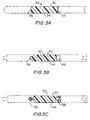
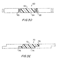
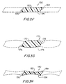
- Figures 3A through 3H are cross-sectional views, taken in a widthwise direction, of several embodiments of the monofilament yarn used to produce the present fabric.
- Each embodiment includes upper and lower surfaces which may be flat (planar) and parallel to one another.
- monofilament yarn 30 has an upper surface 32, a lower surface 34, a cylindrically convex side 36 and a cylindrically concave side 38.
- the upper surface 32 and the lower surface 312 are flat (planar) and parallel to one another.
- the cylindrically convex side 36 and cylindrically concave side 38 have the same radius of curvature, so that the convex side 36 of each spirally wound turn of monofilament yarn 30 fits into the concave side 38 of the immediately preceding turn thereof.
- Each turn of the monofilament yarn 30 is joined to its adjacent turns by joining their respective convex and concave sides 36, 38 to one another by an adhesive, which may be a heat-activated, room-temperature-cured (RTC) or hot-melt adhesive.
- an adhesive which may be a heat-activated, room-temperature-cured (RTC) or hot-melt adhesive.
- monofilament yarn 40 has an upper surface 42, a lower surface 44, a tongue 46 on one side and a corresponding groove 48 on the other side.
- the upper surface 42 and the lower surface 44 are flat (planar) and parallel to one another.
- the tongue 46 has dimensions corresponding to those of the groove 48, so that the tongue 46 on each spirally wound turn of monofilament yarn 40 fits into the groove 48 of the immediately preceding turn thereof.
- Each turn of the monofilament yarn 40 is joined to its adjacent turns by securing tongues 46 in the grooves 48 with an adhesive, which may be a heat-activated, room-temperature-cured (RTC) or hot-melt adhesive.
- RTC room-temperature-cured
- monofilament yarn 50 has an upper surface 52, a lower surface 54, a male interlocking member 56 on one side and a corresponding female interlocking member 58 on the other side.
- the upper surface 52 and the lower surface 54 are flat (planar) and parallel to one another.
- the male interlocking member 56 has rounded dimensions corresponding to those of the female interlocking member 58, so that the male interlocking member 56 on each spirally wound turn of monefilament yarn 50 snappingly fits into the female interlocking member 58 of the immediately preceding turn thereof.
- Each turn of the monofilament yarn 50 may be additionally secured to its adjacent turns by joining the male interlocking member 56 to the female interlocking member 58 with an adhesive, which may be a heat-activated, room-temperature-cured (RTC) or hot-melt adhesive.
- an adhesive which may be a heat-activated, room-temperature-cured (RTC) or hot-melt adhesive.
- monofilament yarn 60 has an upper surface 62, a lower surface 64, a male interlocking member 66 on one side and a corresponding female interlocking member 68 on the other side.
- the upper surface 62 and the lower surface 64 are flat (planar) and parallel to one another.
- the male interlocking member 66 has T-shaped dimensions corresponding to those of the female interlocking member 68, so that the male interlocking member 66 on each spirally wound turn of monofilament yarn 60 snappingly fits into the female interlocking member 68 of the immediately preceding turn thereof.
- Each turn of the monofilament yarn 60 may be additionally secured to its adjacent turns by joining the male interlocking member 66 to the female interlocking member 68 with an adhesive, which may be a heat-activated, room-temperature-cured (RTC) or hot-melt adhesive.
- an adhesive which may be a heat-activated, room-temperature-cured (RTC) or hot-melt adhesive.
- monofilament yarn 70 has an upper surface 72, a lower surface 74, a first portion 76 of reduced thickness lying below the upper surface 72 on one side, and a corresponding second portion 78 of reduced thickness lying above the lower surface 74 on the other side.
- the upper surface 72 and the lower surface 74 are flat (planar) and parallel to one another.
- the first portion 76 has dimensions corresponding to those of the second portion 78, so that the first portion 76 on each spirally wound turn of monofilament yarn 70 fits under the second portion 78 of the immediately preceding turn thereof.
- the first and second portions 76, 78 have a combined thickness equal to that of the monofilament yarn 70 as a whole, so that the fabric manufactured therefrom will have a uniform thickness.
- Each turn of the monofilament yarn 70 is joined to its adjacent turns by securing first portions 76 to second portions 78 with an adhesive, which may be a heat-activated, room-temperature-cured (RTC) or hot-melt adhesive.
- RTC
- monofilament yarn 160 has an upper surface 162, a lower surface 164, a first planar side 166 and a second planar side 168.
- the upper surface 162 and the lower surface 164 are flat (planar) and parallel to one another, and the first planar side 166 and the second planar side 166 are slanted in parallel directions, so that the first planar side 166 of each spirally wound turn of monofilament yarn 160 abuts closely against the second planar side 168 of the immediately preceding turn thereof.
- Each turn of the monofilament yarn 160 is joined to its adjacent turns by joining their respective first and second planar sides 166,168 to one another by an adhesive, which may be a heat-activated, room-temperature-cured (RTC) or hot-melt adhesive.
- an adhesive which may be a heat-activated, room-temperature-cured (RTC) or hot-melt adhesive.
- monofilament yarn 170 has an upper surface 172, a lower surface 174, a first planar side 176 and a second planar side 178.
- the upper surface 172 and the lower surface 174 are convexly rounded in the widthwise direction thereof.
- the first planar side 176 and the second planar side 178 are slanted in parallel directions, so that the first planar side 176 of each spirally wound turn of monofilament yarn 170 abuts closely against the second planar side 178 of the immediately preceding turn thereof.
- Each turn of the monofilament yarn 170 is joined to its adjacent turns by joining their respective first and second planar sides 176, 178 to one another by an adhesive, which may be a heat-activated, room-temperature-cured (RTC) or hot-melt adhesive.
- an adhesive which may be a heat-activated, room-temperature-cured (RTC) or hot-melt adhesive.
- monofilament yarn 180 has an upper surface 182, a lower surface 184, a first planar side 186 and a second planar side 188.
- the upper surface 182 and the lower surface 184 are concavely rounded in the widthwise direction thereof.
- the first planar side 186 and the second planar side 188 are slanted in parallel directions, so that the first planar side 186 of each spirally wound turn of monofilament yarn 180 abuts closely against the second planar side 188 of the immediately preceding turn thereof.
- Each turn of the monofilament yarn 180 is joined to its adjacent turns by joining their respective first and second planar side 186, 188 to one another by an adhesive, which may be a heat-activated, room-temperature-cured (RTC) or hot-melt adhesive.
- an adhesive which may be a heat-activated, room-temperature-cured (RTC) or hot-melt adhesive.
- the monofilament yarns described above may be extruded from any of the polymeric resin materials used by those of ordinary skill in the art to manufacture yarns for paper machine clothing, such as polyamide, polyester, polyurethane and polyketone resins.
- monofilament yarns used to manufacture the fabrics of the present invention will ordinarily have to be provided with passages for conveying water away from a cellulosic fibrous web or other material being conveyed thereon.
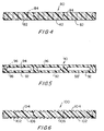
- Figure 4 which is a cross section, taken in a transverse, or cross-machine, direction, of a fabric 80 of the present invention, monofilament yarns 82 are provided along their entire lengths with a plurality of holes 84 for the passage of water from a cellulosic fibrous web.
- FIG. 5 is a cross-sectional view, taken in a transverse direction, of an alternate embodiment of the fabric 90 of the present invention.
- Monofilament yarns 92 are hollow, and include void volume 94 for the storage of water from a cellulosic fibrous web.
- a plurality of holes 96 provided along the entire lengths of the monofilament yarns 92, pass through the monofilament yarn 92 from one of its two surfaces to the void volume.
- a plurality of holes 98 also provided along the entire lengths of the monofilament yarns 92, may pass through the monofilament yarn 92 from the other of its two surfaces to the void volume.
- FIG. 6 is a cross-sectional view, also taken in the transverse direction, of another embodiment of the fabric 100 of the present invention.
- Monofilament yarns 102 have a plurality of grooves 104 on one side thereof for the storage of water from a cellulosic fibrous web.
- the grooves 104 run lengthwise along the monofilament yarn 102.
- a plurality of grooves 106, also running lengthwise along the monofilament yarn 102 may also be provided on the other of the two sides thereof.
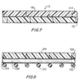
- the fabrics of the present invention may also be laminated structures having a plurality of layers.
- Figure 7 is a cross-sectional view, taken in the transverse direction, of a fabric 110 having two layers 112, 114 of spirally wound monofilament yarns 116.
- One layer 112 may be assembled in the manner described above, and then the second layer 114 may be assembled by spirally winding monofilament yarns 116 onto layer 112.
- the two layers 112,114 may be laminated together with an adhesive, which may be a heat-activated, room-temperature-cured (RTC) or hot-melt adhesive, or with a sheath of low-melt material of the variety manufactured by Sharnet.
- Monofilament yarns 116 may have holes, void volume or grooves as described above.
- Figure 8 is a cross-sectional view, taken in the transverse direction, of another laminated fabric 120.
- Fabric 120 has a first layer 122 of longitudinal yarns 130, a second layer 124 of transverse yarns 132, and a third layer 126 of monofilament yarns 134.
- Longitudinal yarns 130 and transverse yarns 132 are shown to be of circular cross section, but may alternatively have any other cross-sectional shape.
- Fabric 120 may be manufactured by spirally winding longitudinal yarns 130 around first and second process rolls 22, 24 in the same way as described above for monofilament yarns 16, but leaving space between each spiral turn of longitudinal yarn 130.
- transverse yarns 132 are placed at intervals across the longitudinal yarns 130 and secured thereto by an adhesive, which may be a heat-activated, room-temperature-cured (RTC) or hot-melt adhesive.
- an adhesive which may be a heat-activated, room-temperature-cured (RTC) or hot-melt adhesive.
- monofilament yarns 134 are spirally wound onto transverse yarns 132, and joined thereto by an adhesive, which may be a heat-activated, room-temperature-cured (RTC) or hot-melt adhesive, or with a sheath of low-melt material of the variety manufactured by Sharnet.
- Monofilament yarns 134 may have holes, void volume or grooves as described above.
- the order of these manufacturing steps may be reversed by first spirally winding monofilament yarns 134 around first and second process rolls 22,24, by then placing transverse yarns 132 at intervals across the spirally wound monofilament yarns 134, and by finally spirally winding monofilament yarns 130 onto transverse yarns 132.
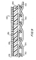
- FIG. 9 is a cross-sectional view, taken in the transverse direction, of yet another laminated fabric 140.
- Fabric 140 comprises a first layer 142, which is a base fabric 150 woven from a system of longitudinal yarns 152 and a system of transverse yarns 154.
- Base fabric 150 is in the form of an endless loop, which is placed in a taut condition about first and second process rolls 22, 24.
- a second layer 144 of monofilament yarns 156 is formed by spirally winding monofilament yarns 156 onto base fabric 150 in the manner described above in the discussion of Figure 2 , and by joining monofilament yarns 156 to base fabric 150 with an adhesive, which may be a heat-activated, room-temperature-cured (RTC) or hot-melt adhesive, or by needling.
- RTC room-temperature-cured
- a second layer 144 of monofilament yarns 156 may have holes, void volume or grooves as described above.
- a third layer 146 of staple fiber batt 158 may be attached to the second layer 144 of monofilament yarns 156 by needling or other means, such as an adhesive, which may be a heat-activated, room-temperature-cured (RTC) or hot-melt adhesive.
- an adhesive which may be a heat-activated, room-temperature-cured (RTC) or hot-melt adhesive.
- staple fiber batt 158 may be used to attach the second layer 144 of monofilamenr yarns 156 to base fabric 150. Additional staple fiber batt can be added to the opposite side of base fabric 150.
- a layer of staple fiber batt may also be provided between first layer 142 and second layer 144. These layers may include non-woven fibrous material, such as those manufactured by Sharnet, or may be entirely composed of such material. These can include spun bonds, melt blowns and the like.
Landscapes
- Engineering & Computer Science (AREA)
- Mechanical Engineering (AREA)
- Paper (AREA)
- Woven Fabrics (AREA)
- Storage Of Web-Like Or Filamentary Materials (AREA)
- Yarns And Mechanical Finishing Of Yarns Or Ropes (AREA)
- Ropes Or Cables (AREA)
- Auxiliary Devices For And Details Of Packaging Control (AREA)
Claims (50)
- Tissu (10) pour les sections de formage, de pressage et de séchage d'une machine à papier, pour l'utilisation en tant que base résistante d'une courroie de traitement de papier revêtue d'une résine polymère ou en tant que courroie pour machine à confectionner le carton ondulé, ou dans d'autres dispositifs industriels où une matière est à égoutter, ledit tissu prenant la forme d'une boucle sans fin et présentant une surface interne (12) et une surface externe (14), caractérisé en ce que ledit tissu comprend:un fil monofilamentaire (16), ce fil monofilamentaire présentant une section non circulaire, une longueur, une surface supérieure (32, 42, 52, 62,72, 162, 172, 182), une surface inférieure (34, 44, 54, 64, 74, 164, 174, 184) et un premier côté (36, 46, 56, 66, 76, 166, 176, 186) ainsi qu'un deuxième côté (38, 48, 58, 68, 78, 168, 178, 188), ledit premier côté et ledit deuxième côté étant opposés l'un à l'autre et présentant des formes complémentaires, ledit fil monofilamentaire étant enroulé en spirale selon une pluralité d'enroulements de façon à ce que ledit premier côté s'emboîte dans ledit deuxième côté d'un enroulement en spirale adjacent dudit fil monofilamentaire, les enroulements en spirale adjacents dudit fil monofilamentaire étant fixés les uns aux autres par les premier et deuxième côtés adjacents afin de former ledit tissu de fabrication du papier.
- Tissu selon la revendication 1, dans lequel au moins une desdites surfaces inférieure et supérieure dudit fil monofilamentaire est plane.
- Tissu selon la revendication 1, dans lequel au moins une desdites surfaces supérieure et inférieure dudit fil monofilamentaire présente une courbure convexe selon le sens de la largeur.
- Tissu selon la revendication 1, dans lequel au moins une desdites surfaces supérieure et inférieure dudit fil monofilamentaire présente une courbure concave selon le sens de la largeur.
- Tissu selon la revendication 1, dans lequel lesdites surfaces supérieure et inférieure dudit fil monofilamentaire sont planes et parallèles.
- Tissu selon la revendication 1, dans lequel ledit premier côté dudit fil monofilamentaire est cylindriquement convexe et ledit deuxième côté dudit fil monofilamentaire est cylindriquement concave, lesdits premier et deuxième côtés présentant le même rayon de courbure, ledit premier côté dudit fil monofilamentaire étant fixé par un adhésif audit deuxième côté d'un enroulement en spirale adjacent dudit fil monofilamentaire.
- Tissu selon la revendication 1, dans lequel ledit premier côté dudit fil monofilamentaire présente une languette et le deuxième côté dudit fil monofilamentaire comporte une rainure, ledit premier côté dudit fil monofilamentaire étant fixé par un adhésif audit deuxième côté d'un enroulement en spirale adjacent dudit fil monofilamentaire.
- Tissu selon la revendication 1, dans lequel ledit premier côté dudit fil monofilamentaire présente un élément de verrouillage mâle arrondi et ledit deuxième côté dudit fil monofilamentaire comporte un élément de verrouillage femelle de forme correspondante, ledit premier côté dudit fil monofilamentaire étant fixé par encliquetage dans ledit premier côté d'un enroulement en spirale adjacent dudit fil monofilamentaire.
- Tissu selon la revendication 1, dans lequel ledit premier côté du fil monofilamentaire présente un élément de verrouillage mâle sous forme de T, et ledit deuxième côté dudit fil monofilamentaire comporte un élément de verrouillage femelle de forme correspondante, ledit premier côté dudit fil monofilamentaire étant fixé par encliquetage dans le deuxième côté d'un enroulement en spirale adjacent dudit fil monofilamentaire.
- Tissu selon la revendication 1, dans lequel ledit premier côté dudit fil monofilamentaire présente une première partie d'épaisseur réduite située au-dessous de ladite surface supérieure dudit fil monofilamentaire, et ledit deuxième côté dudit fil monofilamentaire comporte une deuxième partie d'épaisseur réduite située au-dessus de ladite surface inférieure dudit fil monofilamentaire, ladite première partie dudit premier côté s'insérant au-dessous de ladite deuxième partie sur ledit deuxième côté d'un enroulement en spirale adjacent dudit fil monofilamentaire et étant fixé à celui-ci par un adhésif.
- Tissu selon la revendication 1, dans lequel ledit premier et ledit deuxième côtés dudit fil monofilamentaire sont plans et formés en biais selon des directions parallèles, ledit premier côté dudit fil monofilamentaire étant fixé par un adhésif audit deuxième côté d'un enroulement en spirale adjacent dudit fil monofilamentaire.
- Tissu selon la revendication 1, dans lequel ledit fil monofilamentaire est extrudé à partir d'une matière de résine polymère.
- Tissu selon la revendication 12, dans lequel ladite matière de résine polymère est choisie dans le groupe formé par les résines de polyamide, de polyester, de polyuréthanne et de polycétone.
- Tissu selon la revendication 1, dans lequel ledit fil monofilamentaire présente une pluralité de trous le long de sa longueur, lesdits trous traversant ledit fil monofilamentaire de ladite surface supérieure à ladite surface inférieure.
- Tissu selon la revendication 1, dans lequel ledit fil monofilamentaire est un fil monofilamentaire creux, ledit fil monofilamentaire présentant donc un volume vide pour le stockage temporaire d'eau, et dans lequel ledit fil monofilamentaire présente une première pluralité de trous le long de la longueur, lesdits trous traversant ledit fil monofilamentaire de ladite surface supérieure audit volume vide.
- Tissu selon la revendication 15, dans lequel ledit fil monofilamentaire présente de plus une deuxième pluralité de trous dans le sens de sa longueur, lesdits trous traversant ledit fil monofilamentaire de ladite surface inférieure audit volume vide.
- Tissu selon la revendication 1, dans lequel ladite surface supérieure dudit fil monofilamentaire présente une pluralité de rainures dans le sens de la longueur du fil.
- Tissu selon la revendication 1, dans lequel ladite surface inférieure dudit fil monofilamentaire présente une pluralité de rainures s'étendant dans le sens de sa longueur.
- Tissu selon la revendication 1, comprenant de plus :un deuxième fil monofilamentaire, ledit deuxième fil monofilamentaire présentant une section non circulaire, une longueur, une surface supérieure et une surface inférieure ainsi qu'un premier côté et un deuxième côté, ledit premier côté et ledit deuxième côté étant opposés l'un à l'autre et présentant des formes complémentaires, ledit deuxième fil monofilamentaire étant enroulé en spirale, formant une pluralité d'enroulements de façon à ce que ledit premier côté s'emboîte dans ledit deuxième côté d'un enroulement en spirale adjacent dudit deuxième fil monofilamentaire, les enroulements en spirale adjacents dudit deuxième fil monofilamentaire étant fixés les uns aux autres par les premier et deuxième côtés adjacents afin de former une deuxième couche pour ledit tissu, cette deuxième couche étant laminée à la surface interne ou externe du tissu et attachée à celle-ci.
- Tissu selon la revendication 19, dans lequel lesdites surfaces supérieure et inférieure dudit deuxième fil monofilamentaire sont planes et parallèles.
- Tissu selon la revendication 1, comprenant de plus :une couche de fils attachés à la surface interne ou externe du tissu et s'étendant transversalement sur sa surface.
- Tissu selon la revendication 1, comprenant de plus :une couche de fils attachés à la surface interne ou externe du tissu et s'étendant longitudinalement autour du tissu.
- Tissu selon la revendication 1, comprenant de plus :une première couche de fils attachés à la surface interne ou externe du tissu et s'étendant transversalement sur la surface ; etune deuxième couche de fils attachés à la première couche de fils et s'étendant longitudinalement sur ladite surface interne ou externe dudit tissu.
- Tissu selon la revendication 1, comprenant de plus :un tissu de base tissé sous forme d'une boucle sans fin attaché à la surface interne ou externe dudit tissu.
- Tissu selon la revendication 24, comprenant de plus :un voile de fibres discontinues aiguilleté dans la surface interne ou externe dudit tissu et dans ledit tissu de base tissé, ledit voile de fibres discontinues attachant ainsi ledit tissu audit tissu de base tissé.
- Tissu selon la revendication 24, comprenant de plus :une matière fibreuse non tissée à ladite surface interne ou externe dudit tissu.
- Tissu selon la revendication 24, comprenant de plus :une couche d'un voile de fibres discontinues disposée entre ledit tissu et ledit tissu de base tissé.
- Tissu selon la revendication 24, comprenant de plus :une couche d'une matière fibreuse non tissée disposée entre ledit tissu et ledit tissu de base tissé.
- Tissu selon la revendication 1, comprenant de plus un voile de fibres discontinues attaché à sa surface externe.
- Tissu selon la revendication 1, comprenant de plus un voile de fibres discontinues attaché à sa surface interne.
- Tissu selon la revendication 1, comprenant de plus une matière fibreuse non tissée attachée à sa surface externe.
- Tissu selon la revendication 1, comprenant de plus une matière fibreuse non tissée attachée à sa surface interne.
- Fil monofilamentaire (16) pour l'utilisation dans la construction de toiles de fabrication du papier et d'autres courroies industrielles, caractérisé en ce que ledit fil monofilamentaire présente une section transversale non circulaire, une longueur, une surface supérieure (32, 42, 52, 62, 72, 162, 172, 182) et une surface inférieure (34, 44, 54, 64, 74, 164, 174, 184), un premier côté (36, 46, 56, 66, 76, 166, 176 186) ainsi qu'un deuxième côté (38, 48, 58, 68, 78, 168, 178, 188), ledit premier côté et ledit deuxième côté étant opposés l'un à l'autre et présentant des formes complémentaires de façon à ce que, lorsque ledit fil monofilamentaire est enroulé en spirale selon une hélice fermée présentant une pluralité d'enroulements où ledit premier côté s'emboîte dans ledit deuxième côté d'un enroulement en spirale adjacent de ladite hélice fermée, les enroulements en spirale adjacents au fil monofilamentaire sont fixés les uns aux autres par les premier et deuxième côtés aboutissants.
- Fil monofilamentaire selon la revendication 33, dans lequel lesdites surfaces supérieure et inférieure dudit fil monofilamentaire sont planes et parallèles.
- Fil monofilamentaire selon la revendication 33, dans lequel au moins une desdites surfaces supérieure et inférieure est plane.
- Fil monofilamentaire selon la revendication 33, dans lequel au moins une desdites surfaces supérieure et inférieure présente une courbure convexe dans le sens de la largeur.
- Fil monofilamentaire selon la revendication 33, dans lequel au moins une desdites surfaces supérieure et inférieure présente une courbure concave dans le sens de la largeur.
- Fil monofilamentaire selon la revendication 33, dans lequel ledit premier côté est cylindriquement convexe et ledit deuxième côté est cylindriquement concave, lesdits premier et deuxième côtés ayant le même rayon de courbure.
- Fil monofilamentaire selon la revendication 33, dans lequel ledit premier côté présente une languette et ledit deuxième côté comporte une rainure.
- Fil monofilamentaire selon la revendication 33, dans lequel ledit premier côté présente un élément de verrouillage mâle arrondi et ledit deuxième côté comporte un élément de verrouillage femelle de forme correspondante.
- Fil monofilamentaire selon la revendication 33, dans lequel ledit premier côté présente un élément de verrouillage mâle sous forme de T et ledit deuxième côté comporte un élément de verrouillage femelle de forme correspondante.
- Fil monofilamentaire selon la revendication 33, dans lequel ledit premier côté présente une première partie d'une épaisseur réduite située au-dessous de ladite surface supérieure et le deuxième côté comporte une deuxième partie d'une épaisseur réduite située au-dessus de ladite surface inférieure.
- Fil monofilamentaire selon la revendication 33, dans lequel lesdits premier et deuxième côtés sont plans et coupés en biais selon des directions parallèles.
- Fil monofilamentaire selon la revendication 33, dans lequel ledit fil monofilamentaire est extrudé à partir d'une matière de résine polymère.
- Fil monofilamentaire selon la revendication 44, dans lequel ladite matière de résine polymère est choisie dans le groupe formé par les résines de polyamide, de polyester, de polyuréthanne et de polycétone.
- Fil monofilamentaire selon la revendication 33, comprenant de plus une pluralité de trous dans le sens de la longueur, lesdits trous traversant de ladite surface supérieure à ladite surface inférieure.
- Fil monofilamentaire selon la revendication 33, ledit fil monofilamentaire étant un fil monofilamentaire creux présentant à l'intérieur un volume vide pour le stockage temporaire d'eau, et comprenant de plus une première pluralité de trous situés dans le sens de la longueur, lesdits trous s'étendant de ladite surface supérieure audit volume vide.
- Fil monofilamentaire selon la revendication 47, comprenant de plus une deuxième pluralité de trous situés dans le sens de la longueur du fil, lesdits trous allant de ladite surface inférieure audit volume vide.
- Fil monofilamentaire selon la revendication 33, dans lequel ladite surface supérieure présente une pluralité de rainures s'étendant dans le sens de la longueur du fil.
- Fil monofilamentaire selon la revendication 33, dans lequel ladite surface inférieure présente une pluralité de rainures s'étendant dans le sens de la longueur du fil.
Applications Claiming Priority (3)
| Application Number | Priority Date | Filing Date | Title |
|---|---|---|---|
| US770891 | 2001-01-26 | ||
| US09/770,891 US6630223B2 (en) | 2001-01-26 | 2001-01-26 | Spirally wound shaped yarns for paper machine clothing and industrial belts |
| PCT/US2002/002305 WO2002059419A1 (fr) | 2001-01-26 | 2002-01-25 | Fils enroules en spirale pour garnitures de machine a papier et courroies industrielles |
Publications (2)
| Publication Number | Publication Date |
|---|---|
| EP1354094A1 EP1354094A1 (fr) | 2003-10-22 |
| EP1354094B1 true EP1354094B1 (fr) | 2011-04-13 |
Family
ID=25090025
Family Applications (1)
| Application Number | Title | Priority Date | Filing Date |
|---|---|---|---|
| EP20020703245 Expired - Lifetime EP1354094B1 (fr) | 2001-01-26 | 2002-01-25 | Fils enroules en spirale pour garnitures de machine a papier et courroies industrielles |
Country Status (19)
| Country | Link |
|---|---|
| US (1) | US6630223B2 (fr) |
| EP (1) | EP1354094B1 (fr) |
| JP (1) | JP4069252B2 (fr) |
| KR (1) | KR100694623B1 (fr) |
| CN (1) | CN1240902C (fr) |
| AT (1) | ATE505584T1 (fr) |
| AU (1) | AU2002236878B2 (fr) |
| BR (1) | BR0206622A (fr) |
| CA (1) | CA2434965C (fr) |
| DE (1) | DE60239727D1 (fr) |
| ES (1) | ES2361979T3 (fr) |
| MX (1) | MXPA03006709A (fr) |
| NO (1) | NO20033360L (fr) |
| NZ (1) | NZ527102A (fr) |
| PT (1) | PT1354094E (fr) |
| RU (1) | RU2269612C2 (fr) |
| TW (1) | TWI223020B (fr) |
| WO (1) | WO2002059419A1 (fr) |
| ZA (1) | ZA200305491B (fr) |
Cited By (1)
| Publication number | Priority date | Publication date | Assignee | Title |
|---|---|---|---|---|
| WO2020260153A1 (fr) | 2019-06-26 | 2020-12-30 | Voith Patent Gmbh | Habillage enroulé |
Families Citing this family (38)
| Publication number | Priority date | Publication date | Assignee | Title |
|---|---|---|---|---|
| AT410680B (de) * | 2000-11-22 | 2003-06-25 | Fehrer Monika Mag | Verfahren und vorrichtung zum verfestigen einer textilen warenbahn |
| ES2223995T3 (es) * | 2002-04-25 | 2005-03-01 | THOMAS JOSEF HEIMBACH GESELLSCHAFT MIT BESCHRANKTER HAFTUNG & CO. | Revestimiento de maquina papelera y procedimiento para su fabricacion. |
| ES2262726T3 (es) * | 2002-04-25 | 2006-12-01 | THOMAS JOSEF HEIMBACH GESELLSCHAFT MIT BESCHRANKTER HAFTUNG & CO. | Revestimiento de maquina papelera y procedimiento para su fabricacion. |
| GB0325463D0 (en) * | 2003-10-31 | 2003-12-03 | Voith Fabrics Patent Gmbh | Three dimensional tomographic fabric assembly |
| US7654296B2 (en) * | 2003-11-24 | 2010-02-02 | Albany International Corp. | Grooved single facer belt |
| JP4593326B2 (ja) * | 2004-03-26 | 2010-12-08 | イチカワ株式会社 | シュープレス用ベルト |
| DE102005021026A1 (de) * | 2005-05-06 | 2006-11-09 | Voith Patent Gmbh | Papiermaschinenbespannung |
| DE102005046905A1 (de) * | 2005-09-30 | 2007-04-05 | Voith Patent Gmbh | Papiermaschinenbespannung |
| US9222208B2 (en) * | 2005-12-29 | 2015-12-29 | Albany International Corp. | Elastic silicone rubber belt |
| US7712336B2 (en) * | 2007-01-31 | 2010-05-11 | Albany International Corp. | Subassembly for industrial fabrics |
| US8688874B2 (en) * | 2007-05-15 | 2014-04-01 | Chronologic Pty. Ltd. | Method and system for reducing triggering latency in universal serial bus data acquisition |
| ES2819283T3 (es) * | 2007-09-05 | 2021-04-15 | Albany Int Corp | Proceso para la producción de costura para tela de papelería e industrial y costura producida por ese método |
| DE102007055864A1 (de) * | 2007-12-19 | 2009-06-25 | Voith Patent Gmbh | Transportband und Verfahren zu seiner Herstellung |
| US10590571B2 (en) * | 2007-12-28 | 2020-03-17 | Albany International Corp. | Ultra-resilient pad |
| US10590569B2 (en) * | 2007-12-28 | 2020-03-17 | Albany International Corp. | Ultra-resilient fabric |
| EP2334860B1 (fr) | 2008-09-11 | 2016-01-27 | Albany International Corp. | Tissu industriel et procédé pour sa fabrication |
| BRPI0823070B1 (pt) | 2008-09-11 | 2019-01-02 | Albany Int Corp | estrutura de tecido |
| WO2010057802A2 (fr) | 2008-11-19 | 2010-05-27 | Voith Patent Gmbh | Toile de machine à papier et son procédé de réalisation |
| DE102008043917A1 (de) | 2008-11-20 | 2010-05-27 | Voith Patent Gmbh | Pressfilz und Verfahren zu seiner Herstellung |
| CN106995981A (zh) * | 2008-12-12 | 2017-08-01 | 阿尔巴尼国际公司 | 包括螺旋缠绕材料条带的工业织物 |
| US8728280B2 (en) * | 2008-12-12 | 2014-05-20 | Albany International Corp. | Industrial fabric including spirally wound material strips with reinforcement |
| US8764943B2 (en) * | 2008-12-12 | 2014-07-01 | Albany International Corp. | Industrial fabric including spirally wound material strips with reinforcement |
| BRPI1007355B1 (pt) * | 2009-01-28 | 2020-10-06 | Albany International Corp. | Tecidos de fabrico de papel e sistema e métodos de produção de vazios de atravessamento em tecido de fabrico de papel |
| MX362291B (es) | 2012-05-11 | 2019-01-09 | Albany Int Corp | Tela industrial que incluye tiras de material tejido en espiral con refuerzo. |
| RU2633267C2 (ru) | 2012-05-11 | 2017-10-11 | Олбани Интернешнл Корп. | Техническая ткань, содержащая навитые по спирали полосы материала с усилением |
| WO2014060382A1 (fr) * | 2012-10-19 | 2014-04-24 | Voith Patent Gmbh | Dispositif et procédé de production de fils en matière plastique structurés, fil en matière plastique et toile spiralée constituée de fil en matière plastique |
| US8980062B2 (en) * | 2012-12-26 | 2015-03-17 | Albany International Corp. | Industrial fabric comprising spirally wound material strips and method of making thereof |
| US10259129B2 (en) * | 2014-05-06 | 2019-04-16 | The Johns Hopkins University | Adjustable stiffness morphable manipulator |
| BR112017006124B1 (pt) | 2014-09-25 | 2022-02-08 | Albany International Corp | Correias permeáveis para crepagem ou estruturar uma trama em um processo de produção de tecido |
| BR112017006125B1 (pt) | 2014-09-25 | 2022-02-08 | Albany International Corp | Correia de múltiplas camadas para crepagem e estruturação em um processo de fabricação de papel absorvente |
| BR112017024781A2 (pt) | 2015-05-18 | 2018-08-07 | Albany Int Corp | uso de aditivos de teor de silicone e fluoropolímero para aprimorar propriedades de composições poliméricas |
| TWI717350B (zh) | 2015-10-05 | 2021-02-01 | 美商阿爾巴尼國際公司 | 用來改良聚合性構件之耐磨耗性的組成物及方法 |
| EP3235949B1 (fr) * | 2016-04-21 | 2018-05-23 | Ichikawa Co., Ltd. | Feutre de machine à papier |
| US10280030B2 (en) * | 2016-07-06 | 2019-05-07 | Sew Innovative, Inc. | Fabric organization device |
| WO2019161111A1 (fr) | 2018-02-15 | 2019-08-22 | Donaldson Company, Inc. | Configurations d'éléments filtrants |
| EP3752272A1 (fr) * | 2018-02-15 | 2020-12-23 | Donaldson Company, Inc. | Traitements de substrat |
| DE102021133505A1 (de) * | 2021-12-16 | 2023-06-22 | Voith Patent Gmbh | Grundstruktur, Bespannung und Herstellungsverfahren |
| WO2024006564A1 (fr) * | 2022-07-01 | 2024-01-04 | Albany International Corp. | Courroie industrielle renforcée extrudée |
Family Cites Families (19)
| Publication number | Priority date | Publication date | Assignee | Title |
|---|---|---|---|---|
| DE1245908B (de) | 1967-08-03 | The Lindsay Wire Weaving Company, Cleveland, Ohio (V. St. A.) | Filterband, insbesondere für Papierherstellungsmaschinen | |
| US2943379A (en) | 1958-05-23 | 1960-07-05 | Lockport Felt Company Inc | Papermaker's felt |
| US3097413A (en) | 1960-05-26 | 1963-07-16 | Draper Brothers Company | Unwoven papermaker's felt |
| GB1187256A (en) | 1967-10-13 | 1970-04-08 | Scapa Dryers Ltd | Non-woven Fabrics |
| US4495680A (en) | 1982-02-17 | 1985-01-29 | Appleton Mills | Method and apparatus for forming a helical wound substrate composed solely of longitudinal yarns |
| US4537658A (en) | 1982-09-30 | 1985-08-27 | Scapa Inc. | Papermakers fabric constructed of extruded slotted elements |
| US4594756A (en) | 1983-09-20 | 1986-06-17 | Appleton Mills | Method and apparatus for producing a substrate composed solely of longitudinal yarns |
| US4781967A (en) | 1987-10-07 | 1988-11-01 | The Draper Felt Company, Inc. | Papermaker press felt |
| US4842905A (en) | 1988-02-03 | 1989-06-27 | Asten Group, Inc. | Tessellated papermakers fabric and elements for producing the same |
| DE9007400U1 (de) | 1990-06-13 | 1991-08-14 | Thomas Josef Heimbach GmbH & Co, 5160 Düren | Filz, insbesondere Papiermaschinenfilz |
| SE468602B (sv) | 1990-12-17 | 1993-02-15 | Albany Int Corp | Pressfilt samt saett att framstaella densamma |
| US5208087A (en) | 1991-10-08 | 1993-05-04 | Albany International Corp. | Spiral construction for a long nip press belt |
| US5171389A (en) | 1991-11-08 | 1992-12-15 | Albany International Corp. | Spiral construction of grooved long nip press |
| RU2097184C1 (ru) * | 1995-05-30 | 1997-11-27 | Общество с ограниченной ответственностью "Кавел" | Способ обезвоживания и плавления термопластичных полимерных материалов |
| US6124015A (en) | 1996-04-18 | 2000-09-26 | Jwi Ltd. | Multi-ply industrial fabric having integral jointing structures |
| US5879777A (en) | 1997-06-19 | 1999-03-09 | Asten, Inc. | Modular papermaking fabric |
| DE19814473A1 (de) | 1998-04-01 | 1999-10-07 | Heimbach Gmbh Thomas Josef | Maschinenfilz sowie Verfahren zu dessen Herstellung |
| US6350336B1 (en) | 1999-06-22 | 2002-02-26 | Albany International Corp. | Method of manufacturing a press fabric by spirally attaching a top laminate layer with a heat-activated adhesive |
| US6331341B1 (en) * | 1999-07-09 | 2001-12-18 | Albany International Corp. | Multiaxial press fabric having shaped yarns |
-
2001
- 2001-01-26 US US09/770,891 patent/US6630223B2/en not_active Expired - Lifetime
-
2002
- 2002-01-24 TW TW91101158A patent/TWI223020B/zh not_active IP Right Cessation
- 2002-01-25 BR BR0206622A patent/BR0206622A/pt not_active IP Right Cessation
- 2002-01-25 JP JP2002559897A patent/JP4069252B2/ja not_active Expired - Fee Related
- 2002-01-25 DE DE60239727T patent/DE60239727D1/de not_active Expired - Lifetime
- 2002-01-25 EP EP20020703245 patent/EP1354094B1/fr not_active Expired - Lifetime
- 2002-01-25 WO PCT/US2002/002305 patent/WO2002059419A1/fr not_active Ceased
- 2002-01-25 KR KR1020037009923A patent/KR100694623B1/ko not_active Expired - Fee Related
- 2002-01-25 CA CA 2434965 patent/CA2434965C/fr not_active Expired - Fee Related
- 2002-01-25 MX MXPA03006709A patent/MXPA03006709A/es active IP Right Grant
- 2002-01-25 CN CNB028041038A patent/CN1240902C/zh not_active Expired - Fee Related
- 2002-01-25 PT PT02703245T patent/PT1354094E/pt unknown
- 2002-01-25 ES ES02703245T patent/ES2361979T3/es not_active Expired - Lifetime
- 2002-01-25 AU AU2002236878A patent/AU2002236878B2/en not_active Ceased
- 2002-01-25 RU RU2003123503A patent/RU2269612C2/ru not_active IP Right Cessation
- 2002-01-25 AT AT02703245T patent/ATE505584T1/de active
- 2002-01-25 NZ NZ527102A patent/NZ527102A/en unknown
- 2002-01-25 ZA ZA200305491A patent/ZA200305491B/en unknown
-
2003
- 2003-07-25 NO NO20033360A patent/NO20033360L/no not_active Application Discontinuation
Cited By (1)
| Publication number | Priority date | Publication date | Assignee | Title |
|---|---|---|---|---|
| WO2020260153A1 (fr) | 2019-06-26 | 2020-12-30 | Voith Patent Gmbh | Habillage enroulé |
Also Published As
| Publication number | Publication date |
|---|---|
| KR20030079967A (ko) | 2003-10-10 |
| RU2003123503A (ru) | 2005-02-27 |
| NO20033360D0 (no) | 2003-07-25 |
| NO20033360L (no) | 2003-08-13 |
| MXPA03006709A (es) | 2003-10-24 |
| ES2361979T3 (es) | 2011-06-24 |
| CN1488020A (zh) | 2004-04-07 |
| PT1354094E (pt) | 2011-07-05 |
| DE60239727D1 (de) | 2011-05-26 |
| JP2004521195A (ja) | 2004-07-15 |
| WO2002059419A1 (fr) | 2002-08-01 |
| CA2434965A1 (fr) | 2002-08-01 |
| AU2002236878B2 (en) | 2006-11-30 |
| CA2434965C (fr) | 2009-06-23 |
| KR100694623B1 (ko) | 2007-03-13 |
| ZA200305491B (en) | 2004-07-16 |
| TWI223020B (en) | 2004-11-01 |
| US6630223B2 (en) | 2003-10-07 |
| EP1354094A1 (fr) | 2003-10-22 |
| NZ527102A (en) | 2004-03-26 |
| JP4069252B2 (ja) | 2008-04-02 |
| US20020102894A1 (en) | 2002-08-01 |
| BR0206622A (pt) | 2004-02-25 |
| CN1240902C (zh) | 2006-02-08 |
| ATE505584T1 (de) | 2011-04-15 |
| RU2269612C2 (ru) | 2006-02-10 |
Similar Documents
| Publication | Publication Date | Title |
|---|---|---|
| US6630223B2 (en) | Spirally wound shaped yarns for paper machine clothing and industrial belts | |
| AU2002236878A1 (en) | Spirally wound shaped yarns for paper machine clothing and industrial belts | |
| US8394239B2 (en) | Industrial fabric including spirally wound material strips | |
| EP2938780B1 (fr) | Tissu industriel comprenant des bandes de matière enroulées en spirale et son procédé de production | |
| US6240608B1 (en) | Method for joining nonwoven mesh products | |
| US8764943B2 (en) | Industrial fabric including spirally wound material strips with reinforcement | |
| EP2847380B2 (fr) | Tissu industriel comportant des bandes de matériau enroulées en spirale avec renfort | |
| EP1328681B1 (fr) | Ameliorations de toiles de fabrication de papier cousues | |
| AU2002225981A1 (en) | Seamed papermaker's fabrics |
Legal Events
| Date | Code | Title | Description |
|---|---|---|---|
| PUAI | Public reference made under article 153(3) epc to a published international application that has entered the european phase |
Free format text: ORIGINAL CODE: 0009012 |
|
| 17P | Request for examination filed |
Effective date: 20030721 |
|
| AK | Designated contracting states |
Kind code of ref document: A1 Designated state(s): AT BE CH CY DE DK ES FI FR GB GR IE IT LI LU MC NL PT SE TR |
|
| AX | Request for extension of the european patent |
Extension state: AL LT LV MK RO SI |
|
| 17Q | First examination report despatched |
Effective date: 20080918 |
|
| GRAP | Despatch of communication of intention to grant a patent |
Free format text: ORIGINAL CODE: EPIDOSNIGR1 |
|
| GRAS | Grant fee paid |
Free format text: ORIGINAL CODE: EPIDOSNIGR3 |
|
| GRAA | (expected) grant |
Free format text: ORIGINAL CODE: 0009210 |
|
| AK | Designated contracting states |
Kind code of ref document: B1 Designated state(s): AT BE CH CY DE DK ES FI FR GB GR IE IT LI LU MC NL PT SE TR |
|
| REG | Reference to a national code |
Ref country code: GB Ref legal event code: FG4D |
|
| REG | Reference to a national code |
Ref country code: CH Ref legal event code: NV Representative=s name: BUGNION S.A. Ref country code: CH Ref legal event code: EP |
|
| REG | Reference to a national code |
Ref country code: IE Ref legal event code: FG4D |
|
| REF | Corresponds to: |
Ref document number: 60239727 Country of ref document: DE Date of ref document: 20110526 Kind code of ref document: P |
|
| REG | Reference to a national code |
Ref country code: DE Ref legal event code: R096 Ref document number: 60239727 Country of ref document: DE Effective date: 20110526 |
|
| REG | Reference to a national code |
Ref country code: ES Ref legal event code: FG2A Ref document number: 2361979 Country of ref document: ES Kind code of ref document: T3 Effective date: 20110624 |
|
| REG | Reference to a national code |
Ref country code: PT Ref legal event code: SC4A Free format text: AVAILABILITY OF NATIONAL TRANSLATION Effective date: 20110621 |
|
| REG | Reference to a national code |
Ref country code: NL Ref legal event code: T3 |
|
| REG | Reference to a national code |
Ref country code: SE Ref legal event code: TRGR |
|
| PG25 | Lapsed in a contracting state [announced via postgrant information from national office to epo] |
Ref country code: CY Free format text: LAPSE BECAUSE OF FAILURE TO SUBMIT A TRANSLATION OF THE DESCRIPTION OR TO PAY THE FEE WITHIN THE PRESCRIBED TIME-LIMIT Effective date: 20110413 Ref country code: GR Free format text: LAPSE BECAUSE OF FAILURE TO SUBMIT A TRANSLATION OF THE DESCRIPTION OR TO PAY THE FEE WITHIN THE PRESCRIBED TIME-LIMIT Effective date: 20110714 |
|
| PLBE | No opposition filed within time limit |
Free format text: ORIGINAL CODE: 0009261 |
|
| STAA | Information on the status of an ep patent application or granted ep patent |
Free format text: STATUS: NO OPPOSITION FILED WITHIN TIME LIMIT |
|
| PG25 | Lapsed in a contracting state [announced via postgrant information from national office to epo] |
Ref country code: DK Free format text: LAPSE BECAUSE OF FAILURE TO SUBMIT A TRANSLATION OF THE DESCRIPTION OR TO PAY THE FEE WITHIN THE PRESCRIBED TIME-LIMIT Effective date: 20110413 |
|
| 26N | No opposition filed |
Effective date: 20120116 |
|
| REG | Reference to a national code |
Ref country code: DE Ref legal event code: R097 Ref document number: 60239727 Country of ref document: DE Effective date: 20120116 |
|
| PGFP | Annual fee paid to national office [announced via postgrant information from national office to epo] |
Ref country code: PT Payment date: 20120103 Year of fee payment: 11 |
|
| PGFP | Annual fee paid to national office [announced via postgrant information from national office to epo] |
Ref country code: GB Payment date: 20120126 Year of fee payment: 11 |
|
| PGFP | Annual fee paid to national office [announced via postgrant information from national office to epo] |
Ref country code: NL Payment date: 20120130 Year of fee payment: 11 |
|
| PG25 | Lapsed in a contracting state [announced via postgrant information from national office to epo] |
Ref country code: MC Free format text: LAPSE BECAUSE OF NON-PAYMENT OF DUE FEES Effective date: 20120131 |
|
| REG | Reference to a national code |
Ref country code: IE Ref legal event code: MM4A |
|
| PG25 | Lapsed in a contracting state [announced via postgrant information from national office to epo] |
Ref country code: IE Free format text: LAPSE BECAUSE OF NON-PAYMENT OF DUE FEES Effective date: 20120125 |
|
| PGFP | Annual fee paid to national office [announced via postgrant information from national office to epo] |
Ref country code: FR Payment date: 20130211 Year of fee payment: 12 |
|
| PGFP | Annual fee paid to national office [announced via postgrant information from national office to epo] |
Ref country code: ES Payment date: 20120126 Year of fee payment: 11 |
|
| REG | Reference to a national code |
Ref country code: PT Ref legal event code: MM4A Free format text: LAPSE DUE TO NON-PAYMENT OF FEES Effective date: 20130725 |
|
| REG | Reference to a national code |
Ref country code: NL Ref legal event code: V1 Effective date: 20130801 |
|
| GBPC | Gb: european patent ceased through non-payment of renewal fee |
Effective date: 20130125 |
|
| PG25 | Lapsed in a contracting state [announced via postgrant information from national office to epo] |
Ref country code: PT Free format text: LAPSE BECAUSE OF NON-PAYMENT OF DUE FEES Effective date: 20130725 Ref country code: NL Free format text: LAPSE BECAUSE OF NON-PAYMENT OF DUE FEES Effective date: 20130801 |
|
| PG25 | Lapsed in a contracting state [announced via postgrant information from national office to epo] |
Ref country code: GB Free format text: LAPSE BECAUSE OF NON-PAYMENT OF DUE FEES Effective date: 20130125 |
|
| REG | Reference to a national code |
Ref country code: ES Ref legal event code: FD2A Effective date: 20140424 |
|
| PG25 | Lapsed in a contracting state [announced via postgrant information from national office to epo] |
Ref country code: TR Free format text: LAPSE BECAUSE OF FAILURE TO SUBMIT A TRANSLATION OF THE DESCRIPTION OR TO PAY THE FEE WITHIN THE PRESCRIBED TIME-LIMIT Effective date: 20110413 |
|
| PGFP | Annual fee paid to national office [announced via postgrant information from national office to epo] |
Ref country code: SE Payment date: 20140129 Year of fee payment: 13 |
|
| PG25 | Lapsed in a contracting state [announced via postgrant information from national office to epo] |
Ref country code: ES Free format text: LAPSE BECAUSE OF NON-PAYMENT OF DUE FEES Effective date: 20130126 Ref country code: LU Free format text: LAPSE BECAUSE OF NON-PAYMENT OF DUE FEES Effective date: 20120125 |
|
| REG | Reference to a national code |
Ref country code: FR Ref legal event code: ST Effective date: 20140930 |
|
| PG25 | Lapsed in a contracting state [announced via postgrant information from national office to epo] |
Ref country code: FR Free format text: LAPSE BECAUSE OF NON-PAYMENT OF DUE FEES Effective date: 20140131 |
|
| REG | Reference to a national code |
Ref country code: SE Ref legal event code: EUG |
|
| PG25 | Lapsed in a contracting state [announced via postgrant information from national office to epo] |
Ref country code: SE Free format text: LAPSE BECAUSE OF NON-PAYMENT OF DUE FEES Effective date: 20150126 |
|
| PGFP | Annual fee paid to national office [announced via postgrant information from national office to epo] |
Ref country code: FI Payment date: 20170127 Year of fee payment: 16 |
|
| PGFP | Annual fee paid to national office [announced via postgrant information from national office to epo] |
Ref country code: CH Payment date: 20180127 Year of fee payment: 17 |
|
| PGFP | Annual fee paid to national office [announced via postgrant information from national office to epo] |
Ref country code: AT Payment date: 20180104 Year of fee payment: 17 Ref country code: BE Payment date: 20180129 Year of fee payment: 17 Ref country code: IT Payment date: 20180122 Year of fee payment: 17 |
|
| PG25 | Lapsed in a contracting state [announced via postgrant information from national office to epo] |
Ref country code: FI Free format text: LAPSE BECAUSE OF NON-PAYMENT OF DUE FEES Effective date: 20180125 |
|
| PGFP | Annual fee paid to national office [announced via postgrant information from national office to epo] |
Ref country code: DE Payment date: 20190129 Year of fee payment: 18 |
|
| REG | Reference to a national code |
Ref country code: CH Ref legal event code: PL |
|
| REG | Reference to a national code |
Ref country code: AT Ref legal event code: MM01 Ref document number: 505584 Country of ref document: AT Kind code of ref document: T Effective date: 20190125 |
|
| REG | Reference to a national code |
Ref country code: BE Ref legal event code: MM Effective date: 20190131 |
|
| PG25 | Lapsed in a contracting state [announced via postgrant information from national office to epo] |
Ref country code: BE Free format text: LAPSE BECAUSE OF NON-PAYMENT OF DUE FEES Effective date: 20190131 |
|
| PG25 | Lapsed in a contracting state [announced via postgrant information from national office to epo] |
Ref country code: AT Free format text: LAPSE BECAUSE OF NON-PAYMENT OF DUE FEES Effective date: 20190125 Ref country code: CH Free format text: LAPSE BECAUSE OF NON-PAYMENT OF DUE FEES Effective date: 20190131 Ref country code: LI Free format text: LAPSE BECAUSE OF NON-PAYMENT OF DUE FEES Effective date: 20190131 |
|
| PG25 | Lapsed in a contracting state [announced via postgrant information from national office to epo] |
Ref country code: IT Free format text: LAPSE BECAUSE OF NON-PAYMENT OF DUE FEES Effective date: 20190125 |
|
| REG | Reference to a national code |
Ref country code: DE Ref legal event code: R119 Ref document number: 60239727 Country of ref document: DE |
|
| PG25 | Lapsed in a contracting state [announced via postgrant information from national office to epo] |
Ref country code: DE Free format text: LAPSE BECAUSE OF NON-PAYMENT OF DUE FEES Effective date: 20200801 |