EP1354531A2 - Fixation de sangle et boucle - Google Patents
Fixation de sangle et boucle Download PDFInfo
- Publication number
- EP1354531A2 EP1354531A2 EP03252491A EP03252491A EP1354531A2 EP 1354531 A2 EP1354531 A2 EP 1354531A2 EP 03252491 A EP03252491 A EP 03252491A EP 03252491 A EP03252491 A EP 03252491A EP 1354531 A2 EP1354531 A2 EP 1354531A2
- Authority
- EP
- European Patent Office
- Prior art keywords
- buckle
- strap
- arms
- buckle part
- deflectable
- Prior art date
- Legal status (The legal status is an assumption and is not a legal conclusion. Google has not performed a legal analysis and makes no representation as to the accuracy of the status listed.)
- Granted
Links
- 230000035939 shock Effects 0.000 description 5
- 239000000463 material Substances 0.000 description 4
- WYTGDNHDOZPMIW-RCBQFDQVSA-N alstonine Natural products C1=CC2=C3C=CC=CC3=NC2=C2N1C[C@H]1[C@H](C)OC=C(C(=O)OC)[C@H]1C2 WYTGDNHDOZPMIW-RCBQFDQVSA-N 0.000 description 2
- 238000010276 construction Methods 0.000 description 2
- 230000000694 effects Effects 0.000 description 2
- 238000009958 sewing Methods 0.000 description 2
- 230000002459 sustained effect Effects 0.000 description 2
- 230000003466 anti-cipated effect Effects 0.000 description 1
- 230000000712 assembly Effects 0.000 description 1
- 238000000429 assembly Methods 0.000 description 1
- 229920003023 plastic Polymers 0.000 description 1
- 239000004033 plastic Substances 0.000 description 1
- 230000002787 reinforcement Effects 0.000 description 1
Images

Classifications
-
- A—HUMAN NECESSITIES
- A44—HABERDASHERY; JEWELLERY
- A44B—BUTTONS, PINS, BUCKLES, SLIDE FASTENERS, OR THE LIKE
- A44B11/00—Buckles; Similar fasteners for interconnecting straps or the like, e.g. for safety belts
- A44B11/25—Buckles; Similar fasteners for interconnecting straps or the like, e.g. for safety belts with two or more separable parts
-
- A—HUMAN NECESSITIES
- A44—HABERDASHERY; JEWELLERY
- A44B—BUTTONS, PINS, BUCKLES, SLIDE FASTENERS, OR THE LIKE
- A44B11/00—Buckles; Similar fasteners for interconnecting straps or the like, e.g. for safety belts
- A44B11/006—Attachment of buckle to strap
-
- A—HUMAN NECESSITIES
- A44—HABERDASHERY; JEWELLERY
- A44B—BUTTONS, PINS, BUCKLES, SLIDE FASTENERS, OR THE LIKE
- A44B11/00—Buckles; Similar fasteners for interconnecting straps or the like, e.g. for safety belts
- A44B11/25—Buckles; Similar fasteners for interconnecting straps or the like, e.g. for safety belts with two or more separable parts
- A44B11/26—Buckles; Similar fasteners for interconnecting straps or the like, e.g. for safety belts with two or more separable parts with push-button fastenings
- A44B11/266—Buckles; Similar fasteners for interconnecting straps or the like, e.g. for safety belts with two or more separable parts with push-button fastenings with at least one push-button acting parallel to the main plane of the buckle and perpendicularly to the direction of the fastening action
-
- Y—GENERAL TAGGING OF NEW TECHNOLOGICAL DEVELOPMENTS; GENERAL TAGGING OF CROSS-SECTIONAL TECHNOLOGIES SPANNING OVER SEVERAL SECTIONS OF THE IPC; TECHNICAL SUBJECTS COVERED BY FORMER USPC CROSS-REFERENCE ART COLLECTIONS [XRACs] AND DIGESTS
- Y10—TECHNICAL SUBJECTS COVERED BY FORMER USPC
- Y10T—TECHNICAL SUBJECTS COVERED BY FORMER US CLASSIFICATION
- Y10T24/00—Buckles, buttons, clasps, etc.
- Y10T24/40—Buckles
- Y10T24/4088—One-piece
- Y10T24/4093—Looped strap
-
- Y—GENERAL TAGGING OF NEW TECHNOLOGICAL DEVELOPMENTS; GENERAL TAGGING OF CROSS-SECTIONAL TECHNOLOGIES SPANNING OVER SEVERAL SECTIONS OF THE IPC; TECHNICAL SUBJECTS COVERED BY FORMER USPC CROSS-REFERENCE ART COLLECTIONS [XRACs] AND DIGESTS
- Y10—TECHNICAL SUBJECTS COVERED BY FORMER USPC
- Y10T—TECHNICAL SUBJECTS COVERED BY FORMER US CLASSIFICATION
- Y10T24/00—Buckles, buttons, clasps, etc.
- Y10T24/45—Separable-fastener or required component thereof [e.g., projection and cavity to complete interlock]
- Y10T24/45225—Separable-fastener or required component thereof [e.g., projection and cavity to complete interlock] including member having distinct formations and mating member selectively interlocking therewith
- Y10T24/45471—Projection having movable connection between components thereof or variable configuration
- Y10T24/45524—Projection having movable connection between components thereof or variable configuration including resiliently biased projection component or surface segment
-
- Y—GENERAL TAGGING OF NEW TECHNOLOGICAL DEVELOPMENTS; GENERAL TAGGING OF CROSS-SECTIONAL TECHNOLOGIES SPANNING OVER SEVERAL SECTIONS OF THE IPC; TECHNICAL SUBJECTS COVERED BY FORMER USPC CROSS-REFERENCE ART COLLECTIONS [XRACs] AND DIGESTS
- Y10—TECHNICAL SUBJECTS COVERED BY FORMER USPC
- Y10T—TECHNICAL SUBJECTS COVERED BY FORMER US CLASSIFICATION
- Y10T24/00—Buckles, buttons, clasps, etc.
- Y10T24/45—Separable-fastener or required component thereof [e.g., projection and cavity to complete interlock]
- Y10T24/45225—Separable-fastener or required component thereof [e.g., projection and cavity to complete interlock] including member having distinct formations and mating member selectively interlocking therewith
- Y10T24/45471—Projection having movable connection between components thereof or variable configuration
- Y10T24/45524—Projection having movable connection between components thereof or variable configuration including resiliently biased projection component or surface segment
- Y10T24/45539—Cooperating with cavity having side walls and axially biased component capping end
-
- Y—GENERAL TAGGING OF NEW TECHNOLOGICAL DEVELOPMENTS; GENERAL TAGGING OF CROSS-SECTIONAL TECHNOLOGIES SPANNING OVER SEVERAL SECTIONS OF THE IPC; TECHNICAL SUBJECTS COVERED BY FORMER USPC CROSS-REFERENCE ART COLLECTIONS [XRACs] AND DIGESTS
- Y10—TECHNICAL SUBJECTS COVERED BY FORMER USPC
- Y10T—TECHNICAL SUBJECTS COVERED BY FORMER US CLASSIFICATION
- Y10T24/00—Buckles, buttons, clasps, etc.
- Y10T24/45—Separable-fastener or required component thereof [e.g., projection and cavity to complete interlock]
- Y10T24/45225—Separable-fastener or required component thereof [e.g., projection and cavity to complete interlock] including member having distinct formations and mating member selectively interlocking therewith
- Y10T24/45471—Projection having movable connection between components thereof or variable configuration
- Y10T24/45524—Projection having movable connection between components thereof or variable configuration including resiliently biased projection component or surface segment
- Y10T24/45545—Projection having movable connection between components thereof or variable configuration including resiliently biased projection component or surface segment forming total external surface of projection
- Y10T24/4555—Projection having movable connection between components thereof or variable configuration including resiliently biased projection component or surface segment forming total external surface of projection and encircling hollow central area
- Y10T24/45555—Projection having movable connection between components thereof or variable configuration including resiliently biased projection component or surface segment forming total external surface of projection and encircling hollow central area having separate mounting means inserted into area
- Y10T24/4556—Plastic deformation of means or surface required for mounting
-
- Y—GENERAL TAGGING OF NEW TECHNOLOGICAL DEVELOPMENTS; GENERAL TAGGING OF CROSS-SECTIONAL TECHNOLOGIES SPANNING OVER SEVERAL SECTIONS OF THE IPC; TECHNICAL SUBJECTS COVERED BY FORMER USPC CROSS-REFERENCE ART COLLECTIONS [XRACs] AND DIGESTS
- Y10—TECHNICAL SUBJECTS COVERED BY FORMER USPC
- Y10T—TECHNICAL SUBJECTS COVERED BY FORMER US CLASSIFICATION
- Y10T24/00—Buckles, buttons, clasps, etc.
- Y10T24/45—Separable-fastener or required component thereof [e.g., projection and cavity to complete interlock]
- Y10T24/45225—Separable-fastener or required component thereof [e.g., projection and cavity to complete interlock] including member having distinct formations and mating member selectively interlocking therewith
- Y10T24/45471—Projection having movable connection between components thereof or variable configuration
- Y10T24/45524—Projection having movable connection between components thereof or variable configuration including resiliently biased projection component or surface segment
- Y10T24/45545—Projection having movable connection between components thereof or variable configuration including resiliently biased projection component or surface segment forming total external surface of projection
- Y10T24/45581—Projection having movable connection between components thereof or variable configuration including resiliently biased projection component or surface segment forming total external surface of projection having inserted end formed by oppositely biased surface segments
-
- Y—GENERAL TAGGING OF NEW TECHNOLOGICAL DEVELOPMENTS; GENERAL TAGGING OF CROSS-SECTIONAL TECHNOLOGIES SPANNING OVER SEVERAL SECTIONS OF THE IPC; TECHNICAL SUBJECTS COVERED BY FORMER USPC CROSS-REFERENCE ART COLLECTIONS [XRACs] AND DIGESTS
- Y10—TECHNICAL SUBJECTS COVERED BY FORMER USPC
- Y10T—TECHNICAL SUBJECTS COVERED BY FORMER US CLASSIFICATION
- Y10T24/00—Buckles, buttons, clasps, etc.
- Y10T24/45—Separable-fastener or required component thereof [e.g., projection and cavity to complete interlock]
- Y10T24/45225—Separable-fastener or required component thereof [e.g., projection and cavity to complete interlock] including member having distinct formations and mating member selectively interlocking therewith
- Y10T24/45602—Receiving member includes either movable connection between interlocking components or variable configuration cavity
- Y10T24/45775—Receiving member includes either movable connection between interlocking components or variable configuration cavity having resiliently biased interlocking component or segment
- Y10T24/45796—Receiving member includes either movable connection between interlocking components or variable configuration cavity having resiliently biased interlocking component or segment and closed elongated access opening for guiding transverse projection travel after insertion
Definitions
- the present invention relates generally to two part buckles having interconnecting male and female components used on clothing, sporting gear, luggage, safety equipment and the like.
- Buckles are known for use in many different constructions, including, for example, clothing, sporting gear, luggage, safety and other equipment and the like.
- Two-part buckle assemblies are known in a variety of different constructions.
- cooperating first and second buckle parts are provided with structure having interlocking components, allowing releasable locking engagement of the components.
- a female buckle component attached to one part of an article, and a male buckle component attached to another part of the article.
- the female component may be anchored to a bag or luggage, and the male component attached directly to a lid, cover or flap of the bag or luggage.
- one or both of the components may be attached to a strap or the like.
- the female buckle component defines a chamber or pocket having one or more windows.
- the male buckle component includes one or more arms slidable into the pocket, with projections of the arms extending into each window defined in the female buckle component.
- Two-part buckles also are used on adjustable straps such as sport helmet straps, shoulder and waist straps of backpacks, bags and the like.
- adjustable straps such as sport helmet straps, shoulder and waist straps of backpacks, bags and the like.
- one or both of the buckle parts can be secured to the strap it anchors by a serpentine wrapping of the strap through two or more bars of the buckle part.
- the remaining buckle part can be attached to the strap it anchors by simple wrapping and sewing, if length adjustability is required for only one buckle part.
- Buckles on shoulder straps of bags can experience a slow increase in tensile load, as the bag is lifted by one or more straps.
- the buckle also will experience sustained, relatively constant tensile load if the bag is carried or held with the strap or straps supporting the weight of the bag.
- the buckle also can experience shock load if the bag, for example, is jerked or tugged from a support. Sporting equipment, safety equipment and other such applications may exert such shock load forces as a result of their intended use. Such loads are applied directly against the locking features of the male and female buckle components.
- the buckle components must be sufficiently robust to withstand such forces without breaklng or become disengaged unintentionally.
- simply making the arm or arms of the male buckle component stiffer or thicker to resist breaking can make it unacceptably resistant to intentional deflection for intended disengagement of the buckle.
- the arms can be made longer.
- the resulting increased buckle size is undesirable in some applications and uses.
- the present invention provides springing structure integral with the structure of the buckle parts so that loads exerted thereon can be absorbed.
- the present invention provides a two-part buckle with a female buckle part defining a pocket and including a first strap securing structure.
- a male buckle part includes a forward portion insertable into the pocket, and a second strap securing structure.
- the female buckle part and the male buckle part define cooperative, releasable locking structure, and springing structure for absorbing load exerted on the locking structure.
- the present invention provides a male buckle part for a two-part buckle having a female buckle part defining a pocket having lateral windows and a slot.
- the male buckle part has a body and first and second spaced arms extending from the body and adapted and arranged for sliding into and out of the pocket in the female buckle part.
- the arms have lateral projections received in the windows.
- a brace between the arms is connected to each arm near the body, and has a central portion angling away from the body.
- the present invention provides a strap securing structure for a device to be held on a strap, including a deflectable portion about which a strap can be wrapped, adapted for yielding to load applied against the strap securing structure by a strap secured thereto, and a less deflectable portion associated with the deflectable portion to be jointly wrapped therewith by a strap.
- An advantage of the present invention is providing buckle parts that can better absorb forces such as tensile load applied thereto through attached straps, without breaking or disconnecting.
- Another advantage of the present invention is providing a male buckle part for a two-part buckle with stronger arms less likely to break, yet which can be deflected readily for operation and use of the buckle.
- Still another advantage of the present invention is providing a buckle design that uses material efficiently, is compact and provides increased load bearing capabilities for the size of the buckle.
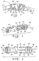
- Buckle 10 includes a male buckle part 12 that can be received and releasably locked in a female buckle part 14.
- Buckle 10 can be made of a variety of materials, with numerous plastics being suitable.
- Buckle 10 can be associated with a variety of different articles, such as luggage, clothing, safety equipment or the like.
- Male buckle part 12 is attached to one article or part of an article and, as illustrated, is shown attached to a strap 16.
- Female buckle part 14 is anchored to another article or part of an article such as a strap 18 illustrated in the drawings. It should be understood that straps 16 and 18 also could be opposite ends of a single piece of webbing, such as when buckle 10 is used for a belt.
- Webs 16 and 18 are illustrated in Fig 1, and, for clarity, are shown as a line designated with the same reference number in Figs. 2 and 3.
- male buckle part 12 is releasably received in and connected to female buckle part 14
- a connecting structure 20 is provided, including male buckle part 12 having forward projecting arms 22 and 24, with enlargements or lateral projections 26 and 28.
- Female buckle part 14 defines therein a hollow chamber or pocket 30 having lateral windows 32 and 34. Windows 32 and 34 are sized and arranged to receive therein projections 26 and 28 from arms 22 and 24, respectively. Arms 22 and 24 deflect inwardly as male buckle part 12 is inserted into female buckle part 14, and spring outwardly to expose projections 26 and 28 through windows 30 and 32 of female buckle part 14, as male buckle part 12 is fully inserted.
- Male buckle part 12 is released from female buckle part 14 by pushing inwardly on projections 26 and 28 while urging male buckle part 12 and female buckle part 14 in opposite directions.
- each male buckle part 12 and female buckle part 14 is provided with integral springing structures for absorbing tensile load exerted against locking structure 20 or against the individual buckle parts 12 and 14.
- Female buckle part 14 includes a first strap securing structure 40, by which strap 18 is secured to female buckle part 14.
- Structure 40 has a base bar 42 and a deflectable bar 44 spaced from each other.
- Deflectable bar 44 is relatively thin compared to base bar 42, and base bar 42 is less deflectable than deflectable bar 44.
- Strap 18 is wrapped jointly around base bar 42 and deflectable bar 44 in a simple loop, doubled back against itself.
- the overlapping end portion of strap 18 is secured to itself by sewing, riveting, adhering or other such fastening system (not shown). Fastened in this manner, the effective length of strap 18 is not readily adjustable.
- truss support members 46 are provided between base bar 42 and deflectable bar 44.
- truss support members 46 are not required. Tensile forces exerted on buckle 10 are absorbed, at least partly, by movement or deflection of deflectable bar 44.
- Male buckle part 12 has an adjustable second strap securing structure 50 by which strap 16 is held in position relative to male buckle part 12.
- Strap securing structure 50 includes a body 52 defining a rearward first web engaging bar 54 and a forward second web engaging bar 56 spaced from each other to form a web-receiving slot 58. Strap 16 is routed in serpentine fashion through body 52, entwining around bars 54 and 56, in known manner, as illustrated. The effective length of strap 16 is adjusted by moving the position of male buckle part 12 along the length of strap 16.
- Forward bar 56 includes a cavity 60 (Figs 2 and 5) extending substantially the length thereof to form a narrow, deflectable forward edge 62. Portions of bar 56 rearward of cavity 60 are less deflectable than forward edge 62.
- Strap 16 wraps a substantial portion of forward bar 56, including deflectable forward edge 62 and less deflectable portions of bar 56. Under severe loading conditions, forces exerted on male buckle part 12 by strap 16 result in a large torque against forward edge 62, due to the lacing configuration for strap 16 in securing structure 50. Forces exerted on buckle 10 in this manner are absorbed, at least partly, by movement or deflection of deflectable forward edge 62.
- Arms 22 and 24 project forwardly from body 52, substantially parallel to each other, but not in linear alignment with body 52.
- a forward portion 64 of male buckle part 12, including arms 22 and 24 thereof is disposed at an angle relative to, and not in linear aligmnent with body 52.
- Arms 22 and 24 are joined to body 52 by thinned connecting segments 66 and 68, respectively, preferably formed from an undercut on the inside of the angle formed between forward portion 64 and body 52.
- connecting segments 66 and 68 function as a hinge, allowing some relative movement between forward portion 64 and body 52.
- forces exerted on buckle 10 through straps 16 and 18 are absorbed, at least partly, by relative movement between forward portion 64 and body 52, in hinge-like manner about connecting segments 66 and 68.
- forward portion 64 of male buckle part 12 includes a brace 70 connected between arms 22 and 24, at bases thereof just forward of connecting segments 66 and 68.
- Brace 70 is of a generally curved v-shape, provided in essentially the same plane as arms 22 and 24.
- Brace 70 has a central portion 72, or apex, thereof angling toward distal ends 74 and 76 of arms 22, and 24, respectively.
- curved brace 70 facilitates lateral movement of distal ends 74 and 76, while also providing reinforcement against breaking of arms 22 and 24.
- arms 22 and 24 can be made of heavy, strong material, yet still can be deflected as necessary for connecting and disconnecting male buckle part 12 from female buckle part 14. Arms 22 and 24 can be made sufficiently strong to resist breaking without becoming unacceptably difficult to deflect laterally as required for using buckle 10.
- a guide pin 78 projects forwardly from brace 70, at central portion 72 thereof, substantially in the same plane as arms 22 and 24. Pin 78 is received in a guide slot of pocket 30, to direct and align forward portion 64 as it is inserted into pocket 30.
- both buckle parts 12 and 14 can be provided with adjustable strap securing structures 50.
- both buckle parts 12 and 14 can be provided with non-adjustable strap securing structures 40, or male buckle part 12 can be provided with a non-adjustable strap securing structure 40 and female buckle part 14 can be provided with an adjustable strap securing structure 50.
- the advantages obtained from the various integral springing structures described are realized regardless of its association with a male or female buckle part 12 or 14, or any particular strap securing structure.
- male buckle part 12 is inserted into pocket 30 of female buckle part 14.
- the tapered, rounding configurations of distal ends 74 and 76 engage inside surfaces of pocket 30 to deflect the arms inwardly as forward portion 64 is forced into pocket 30.
- Laterally extending portions of projections 26 and 28 align with windows 32 and 34, allowing arms 22 and 24 to move outwardly toward the unbiased positions of each.
- Male buckle part 12 is thereby connected to female buckle part 14, with projections 26 and 28 extending outwardly through windows 32 and 34.
- projections 26 and 28 are squeezed together, pushing each inwardly and thereby out of windows 32 and 34, while simultaneously urging buckle parts 12 and 14 apart.
- the various springing structures are not required. However, if an excessive load or a shock load is applied to buckle 10 through straps 16 and 18, the various springing structures operate to absorb at least some of the load, reducing the potential for breakage or accidental disconnect of buckle parts 12 and 14.
- Deflectable bar 44 and deflectable forward edge 62 each can move from force applied directly thereto by straps 16 and 18. The angular relationship between forward portion 64 and body 52 can flatten, as movement occurs about connecting segments 66 and 68. Each of these movements absorbs energy applied to buckle parts 12 and 14, lessening any devastating impact.
- the present invention is particularly suitable for use in two-part buckles of various configurations, including those different from the exemplary embodiment described.
- the various, integral, springing structures described also can be used in two-part buckles having only one or more than two arms.
- the deflectable bars of strap securing structures 40 and 50 can be used advantageously for other devices connected to straps, including buckles of other types as well as for structures other than buckles.
- Advantageous strap securing structures of the present invention include a deflectable portion and a less deflectable portion jointly wrapped by the strap.
- the springing structures described relative to body 52 and forward portion 64 also can be used with other structures.
- the present invention provides a buckle and individual buckle components that can withstand shock loads applied to the buckle such as by jerking the straps or articles attached to the buckle.
- a male buckle component can be provided with strong, thicker arms without making the buckle difficult to operate.
- the flexing design of the buckle parts, with increased strength makes stronger more compact buckles possible.
Landscapes
- Buckles (AREA)
- Automotive Seat Belt Assembly (AREA)
- Outer Garments And Coats (AREA)
- Helmets And Other Head Coverings (AREA)
Applications Claiming Priority (4)
| Application Number | Priority Date | Filing Date | Title |
|---|---|---|---|
| US37335302P | 2002-04-17 | 2002-04-17 | |
| US373353P | 2002-04-17 | ||
| US10/366,744 US6757944B2 (en) | 2002-04-17 | 2003-02-14 | Side release buckle with spring |
| US366744 | 2003-02-14 |
Publications (3)
| Publication Number | Publication Date |
|---|---|
| EP1354531A2 true EP1354531A2 (fr) | 2003-10-22 |
| EP1354531A3 EP1354531A3 (fr) | 2004-08-04 |
| EP1354531B1 EP1354531B1 (fr) | 2008-01-02 |
Family
ID=28678173
Family Applications (1)
| Application Number | Title | Priority Date | Filing Date |
|---|---|---|---|
| EP03252491A Expired - Lifetime EP1354531B1 (fr) | 2002-04-17 | 2003-04-17 | Fixation de sangle et boucle |
Country Status (7)
| Country | Link |
|---|---|
| US (1) | US6757944B2 (fr) |
| EP (1) | EP1354531B1 (fr) |
| KR (1) | KR101006074B1 (fr) |
| AT (1) | ATE382277T1 (fr) |
| DE (1) | DE60318346T2 (fr) |
| ES (1) | ES2298474T3 (fr) |
| TW (1) | TWI239818B (fr) |
Families Citing this family (25)
| Publication number | Priority date | Publication date | Assignee | Title |
|---|---|---|---|---|
| US7841345B2 (en) | 2004-01-16 | 2010-11-30 | Resmed Limited | Headgear connection assembly for a respiratory mask assembly |
| US7753050B2 (en) | 2001-09-07 | 2010-07-13 | Resmed Limited | Headgear connection assembly for a respiratory mask assembly |
| US20070000103A1 (en) * | 2005-06-29 | 2007-01-04 | Joseph Anscher | Shock absorbing buckle |
| US7302742B2 (en) * | 2005-07-20 | 2007-12-04 | Illinois Tool Works Inc | Side-release buckle assembly |
| US20070089280A1 (en) * | 2005-10-24 | 2007-04-26 | Pontaoe John S | Side-release buckle assembly |
| USD535912S1 (en) | 2006-02-10 | 2007-01-30 | Illinois Tool Works Inc. | Buckle member |
| US20070215782A1 (en) * | 2006-03-17 | 2007-09-20 | Phung Trinh D | Chest drainage unit adjustable hanger and method |
| USD558087S1 (en) | 2006-10-04 | 2007-12-25 | Illinois Tool Works Inc | Side release buckle member |
| KR200442058Y1 (ko) * | 2007-04-25 | 2008-10-08 | 천종태 | 도복 띠 마감 부재 |
| ES2322743B1 (es) * | 2007-06-29 | 2010-04-06 | Zobele España, S.A. | Hebilla de liberacion rapida con medios difusores de sustancias volatiles. |
| KR101213328B1 (ko) * | 2008-01-23 | 2012-12-18 | 와이케이케이 가부시끼가이샤 | 버클 |
| USD613509S1 (en) | 2008-10-29 | 2010-04-13 | Travel Caddy, Inc. | Combined buckle and elastic luggage strap |
| US8002095B2 (en) * | 2008-12-18 | 2011-08-23 | Travel Caddy, Inc. | Buckle and elastic luggage strap |
| US20120017347A1 (en) * | 2010-07-21 | 2012-01-26 | Strum David B | Auxiliary Gear Attachment System and Method |
| US10058162B2 (en) * | 2013-03-08 | 2018-08-28 | Munchkin, Inc. | Snap-lock handle for straps |
| US20140260425A1 (en) * | 2013-03-14 | 2014-09-18 | Heartwood Creations, LLC | Bands with buckles & methods & apparatus for displaying band & buckle components |
| KR101500679B1 (ko) * | 2013-09-24 | 2015-03-09 | 주식회사 인텍 | 화물 보호용 아대 |
| US9187939B1 (en) | 2014-01-26 | 2015-11-17 | Jason David Bishop | Safety gate locking strap and a safety gate assembly including the same |
| USD748321S1 (en) * | 2014-05-27 | 2016-01-26 | Illinois Tool Works Inc. | Reflector housing |
| DE112016006357B4 (de) * | 2016-02-05 | 2021-03-11 | Ykk Corporation | Schließe |
| US10306951B2 (en) * | 2016-08-01 | 2019-06-04 | Doskocil Manufacturing Company, Inc | Metal buckle |
| US10610728B2 (en) | 2016-12-27 | 2020-04-07 | Bootymaker, Llc | Devices and methods for targeted isolation and exercising of the gluteal muscles |
| KR102276475B1 (ko) | 2021-01-25 | 2021-07-12 | 김선중 | 버클 |
| KR102413967B1 (ko) | 2021-01-25 | 2022-06-27 | 김선중 | 버클 |
| US20250311798A1 (en) * | 2024-04-05 | 2025-10-09 | shloime klein | Adjustable Fastening Device with Integrated Excess Material Management for Belts and Watch Bands |
Family Cites Families (18)
| Publication number | Priority date | Publication date | Assignee | Title |
|---|---|---|---|---|
| US1999167A (en) * | 1932-04-20 | 1935-04-23 | Parve Products Company | Buckle |
| US1877677A (en) | 1932-06-04 | 1932-09-13 | Ben B Manaster | Garment connecter |
| US3075268A (en) * | 1961-02-09 | 1963-01-29 | S & S Ind Inc | Adjusting strap buckle |
| US3163905A (en) * | 1962-09-20 | 1965-01-05 | Koch & Sons Inc H | Adjustable webbing adapter |
| US3369278A (en) * | 1965-11-08 | 1968-02-20 | Charles D. Humphreys | Reversible belt and buckle having stretch character |
| US3789467A (en) * | 1971-03-01 | 1974-02-05 | Honda Motor Co Ltd | Helmet chin strap |
| US4150464A (en) * | 1977-08-10 | 1979-04-24 | Illinois Tool Works Inc. | Buckle |
| US5170539A (en) | 1991-11-22 | 1992-12-15 | Illinois Tool Works Inc. | Spring loaded sliding bar web connector assembly for a buckle |
| TW301145U (en) * | 1993-10-16 | 1997-03-21 | Yoshida Kogyo Kk | Buckle |
| US5774956A (en) * | 1997-01-24 | 1998-07-07 | Michaels Of Oregon Co. | High-security buckle |
| JP3009366B2 (ja) * | 1997-01-30 | 2000-02-14 | 美生 徳田 | バックル |
| JP3418538B2 (ja) * | 1997-12-24 | 2003-06-23 | ワイケイケイ株式会社 | 合成樹脂製バックルのベルト取付構造 |
| US5893199A (en) * | 1998-05-01 | 1999-04-13 | National Molding Corp. | Buckle with webbing gripping device |
| US5991986A (en) * | 1998-08-28 | 1999-11-30 | Mattel, Inc. | Buckle having misthreading preventor |
| JP4166875B2 (ja) * | 1998-10-01 | 2008-10-15 | 株式会社ニフコ | バックル |
| US6324733B1 (en) * | 1999-11-24 | 2001-12-04 | Ryan L. Brown | Adjustable, quick release clasp |
| JP4299941B2 (ja) * | 2000-02-10 | 2009-07-22 | 株式会社ニフコ | バックル |
| US6378466B1 (en) * | 2000-10-23 | 2002-04-30 | Coastal Pet Products, Inc. | Side release buckle |
-
2003
- 2003-02-14 US US10/366,744 patent/US6757944B2/en not_active Expired - Lifetime
- 2003-04-17 AT AT03252491T patent/ATE382277T1/de not_active IP Right Cessation
- 2003-04-17 KR KR1020030024299A patent/KR101006074B1/ko not_active Expired - Fee Related
- 2003-04-17 TW TW092109185A patent/TWI239818B/zh not_active IP Right Cessation
- 2003-04-17 EP EP03252491A patent/EP1354531B1/fr not_active Expired - Lifetime
- 2003-04-17 DE DE60318346T patent/DE60318346T2/de not_active Expired - Lifetime
- 2003-04-17 ES ES03252491T patent/ES2298474T3/es not_active Expired - Lifetime
Also Published As
| Publication number | Publication date |
|---|---|
| ES2298474T3 (es) | 2008-05-16 |
| DE60318346T2 (de) | 2008-12-18 |
| KR101006074B1 (ko) | 2011-01-06 |
| EP1354531A3 (fr) | 2004-08-04 |
| EP1354531B1 (fr) | 2008-01-02 |
| US20030196302A1 (en) | 2003-10-23 |
| TWI239818B (en) | 2005-09-21 |
| US6757944B2 (en) | 2004-07-06 |
| DE60318346D1 (de) | 2008-02-14 |
| ATE382277T1 (de) | 2008-01-15 |
| KR20030082480A (ko) | 2003-10-22 |
| TW200306793A (en) | 2003-12-01 |
Similar Documents
| Publication | Publication Date | Title |
|---|---|---|
| US6757944B2 (en) | Side release buckle with spring | |
| US4827578A (en) | Harness | |
| US5143266A (en) | Harness | |
| US7155786B2 (en) | Quick release buckle | |
| US7107657B1 (en) | Lanyard operated sternum breakaway buckle with vertical position adjustment | |
| EP1045655B1 (fr) | Ensemble bandouliere | |
| US20100147912A1 (en) | Heavy Tool Tether | |
| MX2007000430A (es) | Arnes de seguridad. | |
| US10694833B2 (en) | Rucksack with continuous back length adjustment | |
| EP4309544B1 (fr) | Unité de réglage, dispositif de fixation et article vestimentaire | |
| EP2268165A2 (fr) | Boucle | |
| US12220024B2 (en) | Buckle | |
| CA2947883C (fr) | Une boucle | |
| US12402680B2 (en) | Fastening device and wearable article with a fastening device | |
| US6154935A (en) | Quick release buckle for use on backpacks and the like | |
| US20030131451A1 (en) | Dual action locking buckle device | |
| US4901408A (en) | Means for fastening suspenders to a garment or other article of clothing | |
| EP1389434B1 (fr) | Dispositif de retenue des extrémités libres de sangles ou ceintures de serrage ou analogues en particulier pour articles d'habillement et gilet compensateur de flottabilité pourvu d'un tel dispositif | |
| US20050015853A1 (en) | Hidden buckle | |
| KR102500649B1 (ko) | 끈 작동형 버클 | |
| CN222466316U (zh) | 背带调节机构和背包 | |
| WO2001024656A1 (fr) | Ensemble de fixation pour dispositifs de telecommunications personnels | |
| GB2330171A (en) | Releasable fixture with a pair of flexible elements and a pin | |
| WO2025096461A1 (fr) | Dispositifs de fermeture magnétique et mécanique, systèmes d'ajustement et systèmes de tension de ligne | |
| WO2025175291A1 (fr) | Boucle magnétique et mécanique, systèmes d'ajustement et systèmes de mise en tension de ligne |
Legal Events
| Date | Code | Title | Description |
|---|---|---|---|
| PUAI | Public reference made under article 153(3) epc to a published international application that has entered the european phase |
Free format text: ORIGINAL CODE: 0009012 |
|
| AK | Designated contracting states |
Kind code of ref document: A2 Designated state(s): AT BE BG CH CY CZ DE DK EE ES FI FR GB GR HU IE IT LI LU MC NL PT RO SE SI SK TR |
|
| AX | Request for extension of the european patent |
Extension state: AL LT LV MK |
|
| PUAL | Search report despatched |
Free format text: ORIGINAL CODE: 0009013 |
|
| AK | Designated contracting states |
Kind code of ref document: A3 Designated state(s): AT BE BG CH CY CZ DE DK EE ES FI FR GB GR HU IE IT LI LU MC NL PT RO SE SI SK TR |
|
| AX | Request for extension of the european patent |
Extension state: AL LT LV MK |
|
| 17P | Request for examination filed |
Effective date: 20050125 |
|
| R17P | Request for examination filed (corrected) |
Effective date: 20050124 |
|
| AKX | Designation fees paid |
Designated state(s): AT BE BG CH CY CZ DE DK EE ES FI FR GB GR HU IE IT LI LU MC NL PT RO SE SI SK TR |
|
| R17P | Request for examination filed (corrected) |
Effective date: 20050124 |
|
| RBV | Designated contracting states (corrected) |
Designated state(s): AT BE BG CH CY CZ DE DK EE ES FI FR GB GR HU IE IT LI LU MC NL PT RO SE SI SK TR |
|
| 17Q | First examination report despatched |
Effective date: 20060314 |
|
| GRAP | Despatch of communication of intention to grant a patent |
Free format text: ORIGINAL CODE: EPIDOSNIGR1 |
|
| GRAS | Grant fee paid |
Free format text: ORIGINAL CODE: EPIDOSNIGR3 |
|
| GRAA | (expected) grant |
Free format text: ORIGINAL CODE: 0009210 |
|
| AK | Designated contracting states |
Kind code of ref document: B1 Designated state(s): AT BE BG CH CY CZ DE DK EE ES FI FR GB GR HU IE IT LI LU MC NL PT RO SE SI SK TR |
|
| REG | Reference to a national code |
Ref country code: GB Ref legal event code: FG4D |
|
| REG | Reference to a national code |
Ref country code: IE Ref legal event code: FG4D |
|
| REG | Reference to a national code |
Ref country code: CH Ref legal event code: EP |
|
| REF | Corresponds to: |
Ref document number: 60318346 Country of ref document: DE Date of ref document: 20080214 Kind code of ref document: P |
|
| REG | Reference to a national code |
Ref country code: ES Ref legal event code: FG2A Ref document number: 2298474 Country of ref document: ES Kind code of ref document: T3 |
|
| PG25 | Lapsed in a contracting state [announced via postgrant information from national office to epo] |
Ref country code: SI Free format text: LAPSE BECAUSE OF FAILURE TO SUBMIT A TRANSLATION OF THE DESCRIPTION OR TO PAY THE FEE WITHIN THE PRESCRIBED TIME-LIMIT Effective date: 20080102 Ref country code: NL Free format text: LAPSE BECAUSE OF FAILURE TO SUBMIT A TRANSLATION OF THE DESCRIPTION OR TO PAY THE FEE WITHIN THE PRESCRIBED TIME-LIMIT Effective date: 20080102 |
|
| NLV1 | Nl: lapsed or annulled due to failure to fulfill the requirements of art. 29p and 29m of the patents act | ||
| PG25 | Lapsed in a contracting state [announced via postgrant information from national office to epo] |
Ref country code: CH Free format text: LAPSE BECAUSE OF FAILURE TO SUBMIT A TRANSLATION OF THE DESCRIPTION OR TO PAY THE FEE WITHIN THE PRESCRIBED TIME-LIMIT Effective date: 20080102 Ref country code: LI Free format text: LAPSE BECAUSE OF FAILURE TO SUBMIT A TRANSLATION OF THE DESCRIPTION OR TO PAY THE FEE WITHIN THE PRESCRIBED TIME-LIMIT Effective date: 20080102 Ref country code: FI Free format text: LAPSE BECAUSE OF FAILURE TO SUBMIT A TRANSLATION OF THE DESCRIPTION OR TO PAY THE FEE WITHIN THE PRESCRIBED TIME-LIMIT Effective date: 20080102 |
|
| REG | Reference to a national code |
Ref country code: CH Ref legal event code: PL |
|
| PG25 | Lapsed in a contracting state [announced via postgrant information from national office to epo] |
Ref country code: BG Free format text: LAPSE BECAUSE OF FAILURE TO SUBMIT A TRANSLATION OF THE DESCRIPTION OR TO PAY THE FEE WITHIN THE PRESCRIBED TIME-LIMIT Effective date: 20080402 Ref country code: AT Free format text: LAPSE BECAUSE OF FAILURE TO SUBMIT A TRANSLATION OF THE DESCRIPTION OR TO PAY THE FEE WITHIN THE PRESCRIBED TIME-LIMIT Effective date: 20080102 |
|
| PG25 | Lapsed in a contracting state [announced via postgrant information from national office to epo] |
Ref country code: BE Free format text: LAPSE BECAUSE OF FAILURE TO SUBMIT A TRANSLATION OF THE DESCRIPTION OR TO PAY THE FEE WITHIN THE PRESCRIBED TIME-LIMIT Effective date: 20080102 Ref country code: PT Free format text: LAPSE BECAUSE OF FAILURE TO SUBMIT A TRANSLATION OF THE DESCRIPTION OR TO PAY THE FEE WITHIN THE PRESCRIBED TIME-LIMIT Effective date: 20080602 |
|
| EN | Fr: translation not filed | ||
| PG25 | Lapsed in a contracting state [announced via postgrant information from national office to epo] |
Ref country code: CZ Free format text: LAPSE BECAUSE OF FAILURE TO SUBMIT A TRANSLATION OF THE DESCRIPTION OR TO PAY THE FEE WITHIN THE PRESCRIBED TIME-LIMIT Effective date: 20080102 Ref country code: DK Free format text: LAPSE BECAUSE OF FAILURE TO SUBMIT A TRANSLATION OF THE DESCRIPTION OR TO PAY THE FEE WITHIN THE PRESCRIBED TIME-LIMIT Effective date: 20080102 Ref country code: SK Free format text: LAPSE BECAUSE OF FAILURE TO SUBMIT A TRANSLATION OF THE DESCRIPTION OR TO PAY THE FEE WITHIN THE PRESCRIBED TIME-LIMIT Effective date: 20080102 Ref country code: SE Free format text: LAPSE BECAUSE OF FAILURE TO SUBMIT A TRANSLATION OF THE DESCRIPTION OR TO PAY THE FEE WITHIN THE PRESCRIBED TIME-LIMIT Effective date: 20080402 |
|
| PLBE | No opposition filed within time limit |
Free format text: ORIGINAL CODE: 0009261 |
|
| STAA | Information on the status of an ep patent application or granted ep patent |
Free format text: STATUS: NO OPPOSITION FILED WITHIN TIME LIMIT |
|
| PG25 | Lapsed in a contracting state [announced via postgrant information from national office to epo] |
Ref country code: MC Free format text: LAPSE BECAUSE OF NON-PAYMENT OF DUE FEES Effective date: 20080430 Ref country code: RO Free format text: LAPSE BECAUSE OF FAILURE TO SUBMIT A TRANSLATION OF THE DESCRIPTION OR TO PAY THE FEE WITHIN THE PRESCRIBED TIME-LIMIT Effective date: 20080102 |
|
| 26N | No opposition filed |
Effective date: 20081003 |
|
| GBPC | Gb: european patent ceased through non-payment of renewal fee |
Effective date: 20080417 |
|
| PG25 | Lapsed in a contracting state [announced via postgrant information from national office to epo] |
Ref country code: EE Free format text: LAPSE BECAUSE OF FAILURE TO SUBMIT A TRANSLATION OF THE DESCRIPTION OR TO PAY THE FEE WITHIN THE PRESCRIBED TIME-LIMIT Effective date: 20080102 |
|
| PG25 | Lapsed in a contracting state [announced via postgrant information from national office to epo] |
Ref country code: IE Free format text: LAPSE BECAUSE OF NON-PAYMENT OF DUE FEES Effective date: 20080417 Ref country code: FR Free format text: LAPSE BECAUSE OF FAILURE TO SUBMIT A TRANSLATION OF THE DESCRIPTION OR TO PAY THE FEE WITHIN THE PRESCRIBED TIME-LIMIT Effective date: 20081024 |
|
| PG25 | Lapsed in a contracting state [announced via postgrant information from national office to epo] |
Ref country code: GB Free format text: LAPSE BECAUSE OF NON-PAYMENT OF DUE FEES Effective date: 20080417 |
|
| PG25 | Lapsed in a contracting state [announced via postgrant information from national office to epo] |
Ref country code: CY Free format text: LAPSE BECAUSE OF FAILURE TO SUBMIT A TRANSLATION OF THE DESCRIPTION OR TO PAY THE FEE WITHIN THE PRESCRIBED TIME-LIMIT Effective date: 20080102 |
|
| PG25 | Lapsed in a contracting state [announced via postgrant information from national office to epo] |
Ref country code: LU Free format text: LAPSE BECAUSE OF NON-PAYMENT OF DUE FEES Effective date: 20080417 Ref country code: HU Free format text: LAPSE BECAUSE OF FAILURE TO SUBMIT A TRANSLATION OF THE DESCRIPTION OR TO PAY THE FEE WITHIN THE PRESCRIBED TIME-LIMIT Effective date: 20080703 |
|
| PG25 | Lapsed in a contracting state [announced via postgrant information from national office to epo] |
Ref country code: TR Free format text: LAPSE BECAUSE OF FAILURE TO SUBMIT A TRANSLATION OF THE DESCRIPTION OR TO PAY THE FEE WITHIN THE PRESCRIBED TIME-LIMIT Effective date: 20080102 |
|
| PG25 | Lapsed in a contracting state [announced via postgrant information from national office to epo] |
Ref country code: GR Free format text: LAPSE BECAUSE OF FAILURE TO SUBMIT A TRANSLATION OF THE DESCRIPTION OR TO PAY THE FEE WITHIN THE PRESCRIBED TIME-LIMIT Effective date: 20080403 |
|
| PGFP | Annual fee paid to national office [announced via postgrant information from national office to epo] |
Ref country code: DE Payment date: 20110427 Year of fee payment: 9 |
|
| PGFP | Annual fee paid to national office [announced via postgrant information from national office to epo] |
Ref country code: ES Payment date: 20120426 Year of fee payment: 10 |
|
| REG | Reference to a national code |
Ref country code: DE Ref legal event code: R119 Ref document number: 60318346 Country of ref document: DE Effective date: 20121101 |
|
| PGFP | Annual fee paid to national office [announced via postgrant information from national office to epo] |
Ref country code: IT Payment date: 20130422 Year of fee payment: 11 |
|
| PG25 | Lapsed in a contracting state [announced via postgrant information from national office to epo] |
Ref country code: DE Free format text: LAPSE BECAUSE OF NON-PAYMENT OF DUE FEES Effective date: 20121101 |
|
| PG25 | Lapsed in a contracting state [announced via postgrant information from national office to epo] |
Ref country code: IT Free format text: LAPSE BECAUSE OF NON-PAYMENT OF DUE FEES Effective date: 20140417 |
|
| REG | Reference to a national code |
Ref country code: ES Ref legal event code: FD2A Effective date: 20150527 |
|
| PG25 | Lapsed in a contracting state [announced via postgrant information from national office to epo] |
Ref country code: ES Free format text: LAPSE BECAUSE OF NON-PAYMENT OF DUE FEES Effective date: 20140418 |