JP4166875B2 - バックル - Google Patents
バックル Download PDFInfo
- Publication number
- JP4166875B2 JP4166875B2 JP28033098A JP28033098A JP4166875B2 JP 4166875 B2 JP4166875 B2 JP 4166875B2 JP 28033098 A JP28033098 A JP 28033098A JP 28033098 A JP28033098 A JP 28033098A JP 4166875 B2 JP4166875 B2 JP 4166875B2
- Authority
- JP
- Japan
- Prior art keywords
- male member
- elastic piece
- buckle
- female member
- length
- Prior art date
- Legal status (The legal status is an assumption and is not a legal conclusion. Google has not performed a legal analysis and makes no representation as to the accuracy of the status listed.)
- Expired - Lifetime
Links
- 230000037431 insertion Effects 0.000 claims description 13
- 238000003780 insertion Methods 0.000 claims description 13
- 238000005452 bending Methods 0.000 description 4
- 238000010586 diagram Methods 0.000 description 2
- 229920003023 plastic Polymers 0.000 description 2
- 239000004033 plastic Substances 0.000 description 2
- 238000004904 shortening Methods 0.000 description 2
- 230000000694 effects Effects 0.000 description 1
- 230000000149 penetrating effect Effects 0.000 description 1
Images




Classifications
-
- A—HUMAN NECESSITIES
- A44—HABERDASHERY; JEWELLERY
- A44B—BUTTONS, PINS, BUCKLES, SLIDE FASTENERS, OR THE LIKE
- A44B11/00—Buckles; Similar fasteners for interconnecting straps or the like, e.g. for safety belts
- A44B11/25—Buckles; Similar fasteners for interconnecting straps or the like, e.g. for safety belts with two or more separable parts
-
- A—HUMAN NECESSITIES
- A44—HABERDASHERY; JEWELLERY
- A44B—BUTTONS, PINS, BUCKLES, SLIDE FASTENERS, OR THE LIKE
- A44B11/00—Buckles; Similar fasteners for interconnecting straps or the like, e.g. for safety belts
- A44B11/25—Buckles; Similar fasteners for interconnecting straps or the like, e.g. for safety belts with two or more separable parts
- A44B11/26—Buckles; Similar fasteners for interconnecting straps or the like, e.g. for safety belts with two or more separable parts with push-button fastenings
- A44B11/266—Buckles; Similar fasteners for interconnecting straps or the like, e.g. for safety belts with two or more separable parts with push-button fastenings with at least one push-button acting parallel to the main plane of the buckle and perpendicularly to the direction of the fastening action
-
- Y—GENERAL TAGGING OF NEW TECHNOLOGICAL DEVELOPMENTS; GENERAL TAGGING OF CROSS-SECTIONAL TECHNOLOGIES SPANNING OVER SEVERAL SECTIONS OF THE IPC; TECHNICAL SUBJECTS COVERED BY FORMER USPC CROSS-REFERENCE ART COLLECTIONS [XRACs] AND DIGESTS
- Y10—TECHNICAL SUBJECTS COVERED BY FORMER USPC
- Y10T—TECHNICAL SUBJECTS COVERED BY FORMER US CLASSIFICATION
- Y10T24/00—Buckles, buttons, clasps, etc.
- Y10T24/45—Separable-fastener or required component thereof [e.g., projection and cavity to complete interlock]
- Y10T24/45225—Separable-fastener or required component thereof [e.g., projection and cavity to complete interlock] including member having distinct formations and mating member selectively interlocking therewith
- Y10T24/45471—Projection having movable connection between components thereof or variable configuration
- Y10T24/45524—Projection having movable connection between components thereof or variable configuration including resiliently biased projection component or surface segment
- Y10T24/45529—Requiring manual force applied against bias to interlock or disengage
- Y10T24/45534—Requiring manual force applied against bias to interlock or disengage having connected leading edge and separated trailing arms
-
- Y—GENERAL TAGGING OF NEW TECHNOLOGICAL DEVELOPMENTS; GENERAL TAGGING OF CROSS-SECTIONAL TECHNOLOGIES SPANNING OVER SEVERAL SECTIONS OF THE IPC; TECHNICAL SUBJECTS COVERED BY FORMER USPC CROSS-REFERENCE ART COLLECTIONS [XRACs] AND DIGESTS
- Y10—TECHNICAL SUBJECTS COVERED BY FORMER USPC
- Y10T—TECHNICAL SUBJECTS COVERED BY FORMER US CLASSIFICATION
- Y10T24/00—Buckles, buttons, clasps, etc.
- Y10T24/45—Separable-fastener or required component thereof [e.g., projection and cavity to complete interlock]
- Y10T24/45225—Separable-fastener or required component thereof [e.g., projection and cavity to complete interlock] including member having distinct formations and mating member selectively interlocking therewith
- Y10T24/45471—Projection having movable connection between components thereof or variable configuration
- Y10T24/45524—Projection having movable connection between components thereof or variable configuration including resiliently biased projection component or surface segment
- Y10T24/45545—Projection having movable connection between components thereof or variable configuration including resiliently biased projection component or surface segment forming total external surface of projection
- Y10T24/4555—Projection having movable connection between components thereof or variable configuration including resiliently biased projection component or surface segment forming total external surface of projection and encircling hollow central area
- Y10T24/45555—Projection having movable connection between components thereof or variable configuration including resiliently biased projection component or surface segment forming total external surface of projection and encircling hollow central area having separate mounting means inserted into area
- Y10T24/4556—Plastic deformation of means or surface required for mounting
-
- Y—GENERAL TAGGING OF NEW TECHNOLOGICAL DEVELOPMENTS; GENERAL TAGGING OF CROSS-SECTIONAL TECHNOLOGIES SPANNING OVER SEVERAL SECTIONS OF THE IPC; TECHNICAL SUBJECTS COVERED BY FORMER USPC CROSS-REFERENCE ART COLLECTIONS [XRACs] AND DIGESTS
- Y10—TECHNICAL SUBJECTS COVERED BY FORMER USPC
- Y10T—TECHNICAL SUBJECTS COVERED BY FORMER US CLASSIFICATION
- Y10T24/00—Buckles, buttons, clasps, etc.
- Y10T24/45—Separable-fastener or required component thereof [e.g., projection and cavity to complete interlock]
- Y10T24/45225—Separable-fastener or required component thereof [e.g., projection and cavity to complete interlock] including member having distinct formations and mating member selectively interlocking therewith
- Y10T24/45471—Projection having movable connection between components thereof or variable configuration
- Y10T24/45524—Projection having movable connection between components thereof or variable configuration including resiliently biased projection component or surface segment
- Y10T24/45545—Projection having movable connection between components thereof or variable configuration including resiliently biased projection component or surface segment forming total external surface of projection
- Y10T24/45581—Projection having movable connection between components thereof or variable configuration including resiliently biased projection component or surface segment forming total external surface of projection having inserted end formed by oppositely biased surface segments
-
- Y—GENERAL TAGGING OF NEW TECHNOLOGICAL DEVELOPMENTS; GENERAL TAGGING OF CROSS-SECTIONAL TECHNOLOGIES SPANNING OVER SEVERAL SECTIONS OF THE IPC; TECHNICAL SUBJECTS COVERED BY FORMER USPC CROSS-REFERENCE ART COLLECTIONS [XRACs] AND DIGESTS
- Y10—TECHNICAL SUBJECTS COVERED BY FORMER USPC
- Y10T—TECHNICAL SUBJECTS COVERED BY FORMER US CLASSIFICATION
- Y10T24/00—Buckles, buttons, clasps, etc.
- Y10T24/45—Separable-fastener or required component thereof [e.g., projection and cavity to complete interlock]
- Y10T24/45225—Separable-fastener or required component thereof [e.g., projection and cavity to complete interlock] including member having distinct formations and mating member selectively interlocking therewith
- Y10T24/45602—Receiving member includes either movable connection between interlocking components or variable configuration cavity
- Y10T24/45623—Receiving member includes either movable connection between interlocking components or variable configuration cavity and operator therefor
Landscapes
- Buckles (AREA)
- Clamps And Clips (AREA)
Description
【発明の属する技術分野】
この発明は、例えばベルトやストラッパなどの両端を相互に連結する分離可能な雌部材と雄部材とからなるバックルに関するものである。
【0002】
【従来の技術】
従来の上記したバックルは、挿入孔および係止部が設けられた中空筒形の雌部材と、鍔部の前面の両端部に、雌部材の係止部に係合する係合部が先端に設けられた雌部材の挿入孔へ挿入される弾性片を対向させて設けた雄部材とで構成されている。
上記した雌部材を構成する扁平な中空筒は、前面を開放させて挿入孔が設けられ、上下壁に開口を形成して係止部が設けられるとともに、後端に、例えばベルトの端部を取り付けたり、固定する取付機構が設けられている。
また、雄部材の鍔部にも、ベルトの端部を取り付けたり、固定する取付機構が設けられている。
そして、弾性片は、鍔部の前面に起立させて設けられている。
【0003】
次に、バックルの着脱について説明する。
まず、取付機構を利用してベルトの両端部を雌部材および雄部材に取り付け、雄部材の係合部を雌部材の中空筒内へ、すなわち挿入孔へ挿入すると、各係合部が中空筒の上下壁の内側に衝合することにより、各弾性片が内側へ撓むので、弾性片を中空筒内へ挿入することができる。
そして、鍔部が中空筒に衝合する状態まで係合部および弾性片を中空筒内へ挿入すると、各係合部が開口と対向するので、弾性片の付勢力で各係合部が各開口内へ突入し、開口を形成する前側縁である係止部に係合し、雌部材と雄部材とは結合される。
【0004】
また、雌部材と雄部材とを分離させる場合は、各開口部分に指を宛って各係合部を押して弾性片を撓ませることにより、各係合部の係止部との係合を解除させた状態のままで雌部材と雄部材とを相対的に離れる方向へ移動させることにより、雌部材と雄部材とを分離させることができる。
なお、このようなバックルは、例えば特開昭59−82803号公報に開示されている。
【0005】
【発明が解決しようとする課題】
従来のバックルの雄部材は、鍔部の前面から弾性片が起立している。
したがって、ベルトの幅が広い場合、雌部材と雄部材とを結合させたバックルの全長が長くても、バックルの幅(縦)と全長(横)とのバランスを保つことができる。
【0006】
しかし、ベルトの幅が狭くなった場合、弾性片の撓み代を確保しなければならないので、弾性片の長さを短くすることができないため、雌部材と雄部材とを結合させたバックルの全長を短くすることができず、幅(縦)と全長(横)とのバランスが崩れ、横長のバックルになってしまうという不都合があった。
【0007】
この発明は、上記したような不都合を解消するためになされたもので、ベルトなどの幅が狭くなった場合、弾性片の長さおよび撓み代を確保しつつ雄部材の全長を短くすることにより、雌部材と雄部材とを結合させた全長が横長にならないようにすることのできるバックルを提供するものである。
【0008】
【課題を解決するための手段】
この発明は、挿入孔および係止部が設けられた中空筒形の雌部材と、取付機構を構成する孔が設けられた鍔部の前面の両端部に、係止部に係合する係合部が先端に設けられ、挿入孔へ挿入される弾性片を対向させて設けた雄部材とからなるバックルにおいて、鍔部の前面の両端部に、鍔部と連結される弾性片の根本部分と、この根本部分と前記孔との間に位置する凹部とを設け、この凹部と孔とを長さ方向でオーバーラップさせるとともに、鍔部と弾性片とを長さ方向でオーバーラップさせたものである。
【0009】
【発明の実施の形態】
以下、この発明の実施形態を図に基づいて説明する。
図1はこの発明の一実施形態であるバックルを構成する雌部材の正面図、図2は図1に示した雌部材の底面図、図3は図1のA−A線による断面図、図4は図2のB−B線による断面図である。
図1〜図4において、1はプラスチックで成形された雌部材を示し、扁平な中空筒2と、この中空筒2の後端に上下に差し渡されて連設された平板部8とで構成されている。
【0010】
上記した中空筒2は、前面から後端まで開放させて挿入孔3が設けられ、上下壁に開口4が設けられて開口4の前側縁が係止部5とされている。
そして、中空筒2の前壁内側に2条のガイドリブ6が連設されるとともに、中空筒2の後ろ壁内側に、ガイドリブ6に対応させて2条のガイドリブ7が連設され、ガイドリブ6,7は後端で連結されてストッパを構成している。
なお、中空筒2と平板部8との間に、ベルトを挿通するための孔9が形成され、平板部8と孔9とによってベルトを取り付ける取付機構が構成されている。
そして、雌部材1は、上下対称に構成されている。
【0011】
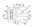
図5はこの発明の一実施形態であるバックルを構成する雄部材の正面図、図6は図5に示した雄部材の底面図、図7は図5のC−C線による断面図、図8は雌部材に雄部材を結合させた状態の雌部材の上側半分を断面とした正面図である。
図5〜図8において、11はプラスチックで成形された雄部材を示し、鍔部12と、この鍔部12の前面12fの両端部に前方へ延びるように連設された中空筒2の挿入孔3へ挿入される弾性片15と、鍔部12の前面12fの中心に前方へ延びるように連設された中空筒2の挿入孔3へ挿入される被ガイド部18とで構成されている。
【0012】
上記した鍔部12には前後へ貫通する孔13が設けられるとともに、この孔13を左右に分割するように軸14が設けられている。
この孔13と軸14とによってベルトを取り付けたり、固定する取付機構が構成されている。
また、各弾性片15の先端には、外側後端が中空筒2の係止部5に係合する係合部16が連設されている。
そして、各弾性片15は、鍔部12の前面12fの両端部分に設けた凹部17の外側に設けられ、鍔部12と長さ方向でオーバーラップしている。
【0013】
上記した被ガイド部18は、中空筒2のガイドリブ6,7で案内されて前後動するものである。
そして、被ガイド部18の先端の上下には、鍔部12が中空筒2に衝合する状態でストッパ(ガイドリブ6,7)に先端が衝合する衝合部19が連設されている。
なお、雄部材11は、上下対称に構成されている。
【0014】
次に、バックルの着脱について説明する。
まず、取付機構を利用してベルトの両端部を雌部材1および雄部材11に取り付け、雄部材11の係合部16を雌部材1の中空筒2内へ、すなわち挿入孔3へ挿入すると、各係合部16が中空筒2の上下壁の内側に衝合することにより、各弾性片15が内側へ撓むので、係合部16および弾性片15を中空筒2内へ挿入することができる。
【0015】
そして、鍔部12が中空筒2に衝合する状態、すなわち図8に示す状態まで係合部16および弾性片15を中空筒2内へ挿入すると、図8に二点鎖線で示すように、各係合部16が各開口4と対向するので、図8に実線で示すように、弾性片15の付勢力で各係合部16が対応する開口4内へ突入して係止部5に係合することにより、雌部材1から雄部材11が抜けないように雌部材1と雄部材11とは結合される。
【0016】
また、雌部材1と雄部材11とを分離させる場合は、各開口4部分に指を宛って各係合部16を押して弾性片15を撓ませることにより、各係合部16の対応する係止部5との係合を解除させた状態のままで雌部材1と雄部材11とを相対的に離れる方向へ移動させることにより、雌部材1と雄部材11とを分離させることができる。
【0017】
図9はこの発明の一実施形態の雄部材と、従来例の雄部材との長さを比較するための説明図である。
なお、下側がこの発明の一実施形態の雄部材であり、上側が従来例の雄部材である。
そして、従来例の雄部材にも、この発明の一実施形態における雄部材と同一の符号が付してある。
【0018】
図9において、aは係合部16を後退させるために必要な弾性片15の長さ、bは鍔部12と弾性片15が長さ方向でオーバーラップするオーバーラップ長を示す。
【0019】
上述したように、この発明の一実施形態によれば、鍔部12の前面12fの両端部に、鍔部12と連結される弾性片15の根本部分と、この根本部分と孔13との間に位置する凹部17とを設けることにより、図9に示すように、凹部17と孔13とを長さ方向でオーバーラップさせるとともに、鍔部12と弾性片15とを長さ方向でオーバーラップさせたので、鍔部12と弾性片15とがオーバーラップするオーバーラップ長bだけ雄部材11の長さを短くすることができ、結合状態におけるバックルの長さを短くすることができる。
【0020】
したがって、ベルトの幅が狭くなった場合、弾性片15の長さおよび撓み代を確保しつつ雄部材11の全長を短くすることにより、雌部材1と雄部材11とを結合させた全長が横長にならないようにすることができ、バックルの幅(縦)と全長(横)とのバランスを保つことができる。
なお、凹部17の深さを深くすればする程、オーバーラップ長bを長くすることができ、雄部材11およびバックルの全長を短くすることができる。
【0021】
【発明の効果】
以上のように、この発明によれば、鍔部の前面の両端部に、鍔部と連結される弾性片の根本部分と、この根本部分と孔との間に位置する凹部とを設けることにより、凹部と孔とを長さ方向でオーバーラップさせるとともに、鍔部と弾性片とを長さ方向でオーバーラップさせたので、鍔部と弾性片とがオーバーラップするオーバーラップ長だけ雄部材の長さを短くすることができ、結合状態におけるバックルの長さを短くすることができる。
したがって、例えばベルトの幅が狭くなった場合、弾性片の長さおよび撓み代を確保しつつ雄部材の全長を短くすることにより、雌部材と雄部材とを結合させた全長が横長にならないようにすることができ、バックルの幅(縦)と全長(横)とのバランスを保つことができる。
【図面の簡単な説明】
【図1】この発明の一実施形態であるバックルを構成する雌部材の正面図である。
【図2】図1に示した雌部材の底面図である。
【図3】図1のA−A線による断面図である。
【図4】図2のB−B線による断面図である。
【図5】この発明の一実施形態であるバックルを構成する雄部材の正面図である。
【図6】図5に示した雄部材の底面図である。
【図7】図5のC−C線による断面図である。
【図8】雌部材に雄部材を結合させた状態の雌部材の上側半分を断面とした正面図である。
【図9】この発明の一実施形態の雄部材と、従来例の雄部材との長さを比較するための説明図である。
【符号の説明】
1 雌部材
2 中空筒
3 挿入孔
4 開口
5 係止部
6,7 ガイドリブ
8 平板部
9 孔
11 雄部材
12 鍔部
12f 前面
13 孔
14 軸
15 弾性片
16 係合部
17 凹部
18 被ガイド部
19 衝合部
Claims (1)
- 挿入孔および係止部が設けられた中空筒形の雌部材と、取付機構を構成する孔が設けられた鍔部の前面の両端部に、前記係止部に係合する係合部が先端に設けられ、前記挿入孔へ挿入される弾性片を対向させて設けた雄部材とからなるバックルにおいて、
前記鍔部の前面の両端部に、前記鍔部と連結される前記弾性片の根本部分と、この根本部分と前記孔との間に位置する凹部とを設け、この凹部と前記孔とを長さ方向でオーバーラップさせるとともに、前記鍔部と前記弾性片とを長さ方向でオーバーラップさせた、
ことを特徴とするバックル。
Priority Applications (6)
| Application Number | Priority Date | Filing Date | Title |
|---|---|---|---|
| JP28033098A JP4166875B2 (ja) | 1998-10-01 | 1998-10-01 | バックル |
| TW088113696A TW403637B (en) | 1998-10-01 | 1999-08-11 | Buckle |
| KR1019990035696A KR100298675B1 (ko) | 1998-10-01 | 1999-08-26 | 버클 |
| CNB991207173A CN1157133C (zh) | 1998-10-01 | 1999-09-27 | 带扣 |
| US09/406,122 US6263548B1 (en) | 1998-10-01 | 1999-09-27 | Buckle with reduced size |
| HK00105902.6A HK1026584B (en) | 1998-10-01 | 2000-09-20 | Buckle |
Applications Claiming Priority (1)
| Application Number | Priority Date | Filing Date | Title |
|---|---|---|---|
| JP28033098A JP4166875B2 (ja) | 1998-10-01 | 1998-10-01 | バックル |
Publications (2)
| Publication Number | Publication Date |
|---|---|
| JP2000106916A JP2000106916A (ja) | 2000-04-18 |
| JP4166875B2 true JP4166875B2 (ja) | 2008-10-15 |
Family
ID=17623513
Family Applications (1)
| Application Number | Title | Priority Date | Filing Date |
|---|---|---|---|
| JP28033098A Expired - Lifetime JP4166875B2 (ja) | 1998-10-01 | 1998-10-01 | バックル |
Country Status (5)
| Country | Link |
|---|---|
| US (1) | US6263548B1 (ja) |
| JP (1) | JP4166875B2 (ja) |
| KR (1) | KR100298675B1 (ja) |
| CN (1) | CN1157133C (ja) |
| TW (1) | TW403637B (ja) |
Families Citing this family (14)
| Publication number | Priority date | Publication date | Assignee | Title |
|---|---|---|---|---|
| USD454092S1 (en) | 2000-04-04 | 2002-03-05 | Shaun C. Lindblad | Buckle |
| US6421889B1 (en) * | 2001-05-31 | 2002-07-23 | Vinsonic Industrial Co., Ltd. | Buckle structure |
| US6757944B2 (en) * | 2002-04-17 | 2004-07-06 | Illinois Tool Works Inc. | Side release buckle with spring |
| US7089633B2 (en) * | 2004-09-15 | 2006-08-15 | Kim Ging Hui Enterprise Co., Ltd. | Side release buckle |
| US7100252B2 (en) | 2005-01-31 | 2006-09-05 | Joseph Anscher | Dual locking buckle |
| US7302742B2 (en) * | 2005-07-20 | 2007-12-04 | Illinois Tool Works Inc | Side-release buckle assembly |
| US20070089280A1 (en) * | 2005-10-24 | 2007-04-26 | Pontaoe John S | Side-release buckle assembly |
| JP4610667B2 (ja) | 2009-06-12 | 2011-01-12 | 久誌 勝連 | 水蒸気爆発及び衝撃波発生装置、発動機及びタービン装置 |
| CN104100811A (zh) * | 2013-04-12 | 2014-10-15 | 纬创资通股份有限公司 | 可插拔以改变支撑角度的脚架机构 |
| EP3019044B1 (en) * | 2013-07-10 | 2017-11-22 | Illinois Tool Works Inc. | Assembly for securing a buckle housing to a component |
| USD799370S1 (en) * | 2016-01-12 | 2017-10-10 | Woojin Plastic Co., Ltd | Female receptacle of buckle |
| US11375777B2 (en) * | 2017-09-15 | 2022-07-05 | Ykk Corporation | Side-release buckle |
| US12171308B2 (en) | 2023-01-31 | 2024-12-24 | Central Lake Armor Express, Inc. | Buckle assembly |
| USD1092292S1 (en) | 2023-01-31 | 2025-09-09 | Central Lake Armored Express, Inc. | Buckle assembly |
Family Cites Families (5)
| Publication number | Priority date | Publication date | Assignee | Title |
|---|---|---|---|---|
| FR2226129A1 (en) * | 1973-04-19 | 1974-11-15 | Beyl Jean Joseph Alfred | Fastener for ends of straps, belts etc. - has spring locking arms in form of V controlled by external finger press |
| IT220555Z2 (it) * | 1990-07-10 | 1993-10-04 | Itw Fastex Italia Spa | Fibbia sganciabile in due elementi |
| TW301145U (en) * | 1993-10-16 | 1997-03-21 | Yoshida Kogyo Kk | Buckle |
| US5794316A (en) * | 1996-06-24 | 1998-08-18 | National Molding Corp. | Side-release buckle having improved locking feature |
| US5774956A (en) * | 1997-01-24 | 1998-07-07 | Michaels Of Oregon Co. | High-security buckle |
-
1998
- 1998-10-01 JP JP28033098A patent/JP4166875B2/ja not_active Expired - Lifetime
-
1999
- 1999-08-11 TW TW088113696A patent/TW403637B/zh not_active IP Right Cessation
- 1999-08-26 KR KR1019990035696A patent/KR100298675B1/ko not_active Expired - Lifetime
- 1999-09-27 US US09/406,122 patent/US6263548B1/en not_active Expired - Lifetime
- 1999-09-27 CN CNB991207173A patent/CN1157133C/zh not_active Expired - Lifetime
Also Published As
| Publication number | Publication date |
|---|---|
| CN1252246A (zh) | 2000-05-10 |
| JP2000106916A (ja) | 2000-04-18 |
| TW403637B (en) | 2000-09-01 |
| KR100298675B1 (ko) | 2001-09-22 |
| HK1026584A1 (en) | 2000-12-22 |
| US6263548B1 (en) | 2001-07-24 |
| CN1157133C (zh) | 2004-07-14 |
| KR20000028621A (ko) | 2000-05-25 |
Similar Documents
| Publication | Publication Date | Title |
|---|---|---|
| KR100490092B1 (ko) | 버클 | |
| KR970014628A (ko) | 커넥터를 구비한 코드 | |
| KR950015866A (ko) | 암형 콘택트 | |
| EP0648441B1 (en) | Buckle | |
| US6351876B1 (en) | Side release buckle | |
| JP2005166604A (ja) | コネクタのロック構造 | |
| JPH0676804B2 (ja) | 2枚のパネルを接面状に止着するための留め具 | |
| JP2007229307A (ja) | バックル | |
| US6263548B1 (en) | Buckle with reduced size | |
| EP0986141A3 (en) | A female terminal for a connector and a housing therefor | |
| JPH0845596A (ja) | コネクタ | |
| JPWO2018212304A1 (ja) | スライドファスナー | |
| US6796837B2 (en) | Connector with lock piece that longitudinally deforms | |
| JPH09163549A (ja) | ロック機構 | |
| JP4520655B2 (ja) | バックル | |
| JP2000166616A (ja) | バックル | |
| JP2003007392A (ja) | コネクタ | |
| ITTO20010914A1 (it) | Disposotivo per il collegamento di una cinghia. | |
| JP2577353Y2 (ja) | 軒樋継手及び軒樋接続装置 | |
| JP2880926B2 (ja) | ケース | |
| US20240246496A1 (en) | Resin-molded article | |
| JP2005146743A (ja) | 軒樋曲がり継手 | |
| JP7294005B2 (ja) | ピラーガーニッシュとパッケージトレイの組付構造 | |
| JP4560476B2 (ja) | 取付部材 | |
| JP2007014174A (ja) | ワイヤーハーネス外装用コルゲートチューブ継手 |
Legal Events
| Date | Code | Title | Description |
|---|---|---|---|
| A621 | Written request for application examination |
Free format text: JAPANESE INTERMEDIATE CODE: A621 Effective date: 20050613 |
|
| A977 | Report on retrieval |
Free format text: JAPANESE INTERMEDIATE CODE: A971007 Effective date: 20061205 |
|
| A131 | Notification of reasons for refusal |
Free format text: JAPANESE INTERMEDIATE CODE: A131 Effective date: 20061212 |
|
| A521 | Request for written amendment filed |
Free format text: JAPANESE INTERMEDIATE CODE: A523 Effective date: 20070205 |
|
| A02 | Decision of refusal |
Free format text: JAPANESE INTERMEDIATE CODE: A02 Effective date: 20080226 |
|
| A521 | Request for written amendment filed |
Free format text: JAPANESE INTERMEDIATE CODE: A523 Effective date: 20080326 |
|
| A911 | Transfer to examiner for re-examination before appeal (zenchi) |
Free format text: JAPANESE INTERMEDIATE CODE: A911 Effective date: 20080430 |
|
| TRDD | Decision of grant or rejection written | ||
| A01 | Written decision to grant a patent or to grant a registration (utility model) |
Free format text: JAPANESE INTERMEDIATE CODE: A01 Effective date: 20080708 |
|
| A01 | Written decision to grant a patent or to grant a registration (utility model) |
Free format text: JAPANESE INTERMEDIATE CODE: A01 |
|
| A61 | First payment of annual fees (during grant procedure) |
Free format text: JAPANESE INTERMEDIATE CODE: A61 Effective date: 20080731 |
|
| R150 | Certificate of patent or registration of utility model |
Free format text: JAPANESE INTERMEDIATE CODE: R150 |
|
| FPAY | Renewal fee payment (event date is renewal date of database) |
Free format text: PAYMENT UNTIL: 20110808 Year of fee payment: 3 |
|
| FPAY | Renewal fee payment (event date is renewal date of database) |
Free format text: PAYMENT UNTIL: 20120808 Year of fee payment: 4 |
|
| FPAY | Renewal fee payment (event date is renewal date of database) |
Free format text: PAYMENT UNTIL: 20130808 Year of fee payment: 5 |
|
| FPAY | Renewal fee payment (event date is renewal date of database) |
Free format text: PAYMENT UNTIL: 20130808 Year of fee payment: 5 |
|
| FPAY | Renewal fee payment (event date is renewal date of database) |
Free format text: PAYMENT UNTIL: 20130808 Year of fee payment: 5 |
|
| R250 | Receipt of annual fees |
Free format text: JAPANESE INTERMEDIATE CODE: R250 |
|
| R250 | Receipt of annual fees |
Free format text: JAPANESE INTERMEDIATE CODE: R250 |
|
| R250 | Receipt of annual fees |
Free format text: JAPANESE INTERMEDIATE CODE: R250 |
|
| R250 | Receipt of annual fees |
Free format text: JAPANESE INTERMEDIATE CODE: R250 |
|
| EXPY | Cancellation because of completion of term |