EP1354654A1 - Vorrichtung zum Schneiden einer Schlüsselkode - Google Patents
Vorrichtung zum Schneiden einer Schlüsselkode Download PDFInfo
- Publication number
- EP1354654A1 EP1354654A1 EP02252785A EP02252785A EP1354654A1 EP 1354654 A1 EP1354654 A1 EP 1354654A1 EP 02252785 A EP02252785 A EP 02252785A EP 02252785 A EP02252785 A EP 02252785A EP 1354654 A1 EP1354654 A1 EP 1354654A1
- Authority
- EP
- European Patent Office
- Prior art keywords
- key
- carriage
- work table
- transverse direction
- along
- Prior art date
- Legal status (The legal status is an assumption and is not a legal conclusion. Google has not performed a legal analysis and makes no representation as to the accuracy of the status listed.)
- Granted
Links
- 238000003801 milling Methods 0.000 claims abstract description 28
- 238000006073 displacement reaction Methods 0.000 claims description 2
- 238000007373 indentation Methods 0.000 description 23
- 230000015572 biosynthetic process Effects 0.000 description 6
- 230000001680 brushing effect Effects 0.000 description 3
- 238000004140 cleaning Methods 0.000 description 1
Images


Classifications
-
- B—PERFORMING OPERATIONS; TRANSPORTING
- B23—MACHINE TOOLS; METAL-WORKING NOT OTHERWISE PROVIDED FOR
- B23C—MILLING
- B23C3/00—Milling particular work; Special milling operations; Machines therefor
- B23C3/28—Grooving workpieces
- B23C3/35—Milling grooves in keys
-
- Y—GENERAL TAGGING OF NEW TECHNOLOGICAL DEVELOPMENTS; GENERAL TAGGING OF CROSS-SECTIONAL TECHNOLOGIES SPANNING OVER SEVERAL SECTIONS OF THE IPC; TECHNICAL SUBJECTS COVERED BY FORMER USPC CROSS-REFERENCE ART COLLECTIONS [XRACs] AND DIGESTS
- Y10—TECHNICAL SUBJECTS COVERED BY FORMER USPC
- Y10T—TECHNICAL SUBJECTS COVERED BY FORMER US CLASSIFICATION
- Y10T409/00—Gear cutting, milling, or planing
- Y10T409/30—Milling
- Y10T409/30084—Milling with regulation of operation by templet, card, or other replaceable information supply
- Y10T409/300952—Milling with regulation of operation by templet, card, or other replaceable information supply to cut lock key
- Y10T409/301008—Using templet other than a key
-
- Y—GENERAL TAGGING OF NEW TECHNOLOGICAL DEVELOPMENTS; GENERAL TAGGING OF CROSS-SECTIONAL TECHNOLOGIES SPANNING OVER SEVERAL SECTIONS OF THE IPC; TECHNICAL SUBJECTS COVERED BY FORMER USPC CROSS-REFERENCE ART COLLECTIONS [XRACs] AND DIGESTS
- Y10—TECHNICAL SUBJECTS COVERED BY FORMER USPC
- Y10T—TECHNICAL SUBJECTS COVERED BY FORMER US CLASSIFICATION
- Y10T409/00—Gear cutting, milling, or planing
- Y10T409/30—Milling
- Y10T409/30084—Milling with regulation of operation by templet, card, or other replaceable information supply
- Y10T409/300952—Milling with regulation of operation by templet, card, or other replaceable information supply to cut lock key
- Y10T409/301064—Complete cycle
Definitions
- This invention relates to a key code cutting device, more particularly to a key code cutting device that includes a key coding member for adjusting positions of a key blank in which the key blank is to be cut according to a code which defines a plurality of spacing each representing a distance between two adjacent cuts on the key blank.
- Fig. 1 illustrates one type of key blank 1 that has a blade portion 102 of a sector-shaped cross-section.
- the blade portion 102 of the key blank 1 has a key groove defined by first and second grooved faces 104, 105.
- a plurality of indentations are to be formed in the second grooved face 105 to make a key.
- a key code cutting device can only cut the blade portion 102 in two dimensions (indicated as X and Z directions in Fig. 1) to form the indentations.
- a key code cutting device of this invention comprises: a base; a milling tool mounted on the base and adapted to mill a key blank; a carriage mounted on the base and movable along a first transverse direction relative to the milling tool; a work table mounted on the carriage and movable toward and away from the milling tool along a second transverse direction relative to the milling tool, the first and second transverse directions being transverse to one another; a key holding member mounted on the work table and having opposite coaxial first and second clamp members which are aligned along the first transverse direction and which are adapted to hold opposite ends of the key blank, the first clamp member being turnable about an axis that extends through centers of the first and second clamp members; an urging member for urging the carriage to move in a direction from the second clamp member to the first clamp member along the first transverse direction; a key coding member mounted on the base and abutting adjustably against the carriage for adjusting positions of the carriage along the first transverse direction and thus cutting positions of the key blank where the
- Fig. 2 illustrates a key that is made from the aforementioned key blank 1.
- a plurality of indentations 106 are formed in the second grooved face 105, and are cut according to a code which defines a plurality of spacing, each representing a distance between two adjacent cuts on the key.
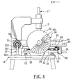
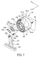
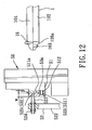
- Figs. 3 to 7 illustrate a key code cutting device embodying this invention and adapted to cut the aforesaid key blank 1 for forming the indentations 106 shown in Fig. 2.
- the key code cutting device includes a base 10, a stand 14 upright from the base 10, a driving unit (not shown), a rotatable shaft 15 mounted on the stand 14 and connected to the driving unit, a milling tool 16 projecting downwardly from the shaft 15, a carriage 20 mounted on the base 10 and movable along a first transverse direction (indicated as "Z" in Fig.
- a work table 22 mounted on the carriage 20 below the milling tool 16 and movable toward and away from the milling tool 16 along a second transverse direction (indicated as "X" in Fig. 4) relative to the milling too 16, a key holding member mounted on the work table 22 and having opposite coaxial first and second clamp members 30, 40 which are aligned along the first transverse direction (Z) and which are adapted to hold opposite ends of the key blank 1 (see Fig.
- an advancing member for moving the work table 22 toward and away from the milling tool 16 along the second transverse direction (X)
- a limiting member 60 mounted adjustably on the carriage 20 for controlling displacement of the work table 22 along the second transverse direction (X) when the work table 22 moves toward the milling tool 16
- an urging member 13 mounted on the base 10 for urging the carriage 20 to move in a direction from the second clamp member 40 to the first clamp member 30 along the first transverse direction (Z)
- a key coding member 50 for adjusting positions of the key blank 1 along the first transverse direction (Z)
- a locking member mounted on the work table 22, a supporting member 25 mounted on the work table 22 between the first and second clamp members 30, 40 for supporting the key blank 1, and a brushing member 17 mounted on the stand 14.
- the first and second transverse directions (Z), (X) are transverse to one another.
- the base 10 includes a pair of parallel guide rods 12 extending in the first transverse direction (Z).
- the carriage 20 includes a plurality of sleeves 21 sleeved around the guide rods 12 so as to be slidable along the guide rods 12.
- the urging member 13 includes a pair of coil springs sleeved respectively around the guide rods 12 and having ends abutting respectively against the sleeves 21 and ends of the guide rods 12 so as to urge the carriage 20 to move toward the first clamp member 30.
- the carriage 20 includes a pair of parallel guide rails 223 extending in the second transverse direction (X).
- the work table 22 is mounted slidably on the guide rails 223 so as to be slidable therealong.
- the advancing member includes a screw rod 23 that extends in the second transverse direction (X) and that threadedly engages the work table 22, and a handle-wheel 24 connected to the screw rod 23 for driving the latter to move the work table 22 along the guide rails 223.
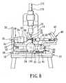
- the first clamp member 30 includes a housing 31 mounted on the work table 22, a rotatable indexing disc 32 mounted on one end of the housing 31, and a turnable first clamp head 36 mounted on the other end of the housing 31 for clamping one end of the key blank 1, and connected to the indexing disc 32.
- the second clamp member 40 includes a seat 44 mounted on the work table 22 opposite to the housing 31, a linkage member 43 mounted movably on the seat 44, a handle 42 connected to one end of the linkage member 43, and a rotatable second clamp head 41 connected to the other end of the linkage member 43 for clamping the other end of the key blank 1.
- the first and second clamp heads 36, 41 and the indexing disc 32 are coaxially turnable about a first axis, which extends through centers of the first and second clamp heads 36, 41 in the first transverse direction (Z), so as to turn the key blank 1 to a desired cutting angle relative to the second grooved face 105 ( see the angle represented by a double-arrow line in Figs. 9 and 10).
- the handle 42 is turnable upwardly and downwardly to move the second clamp head 41 toward and away from the first clamp head 36 in the first transverse direction (Z) so as to clamp the key blank 1 (see Fig. 8).
- the indexing disc 32 is formed with a plurality of successive holes 321, each of which represents a cutting angle to which the key blank 1 can be turned so that different depths of the indentations 106 from the second grooved face 105 in an angular direction can be formed in the blade portion 102 of the key blank 1.
- These successive holes 321 represent cutting angles ranging from 0 to 180° .
- the locking member includes a slide 34 mounted slidably on a guide rail 33 of the work table 22, a linkage plate 35 pivoted on the slide 34 and extending to the indexing disc 32, and a locking pin 351 projecting from the linkage plate 35 into a desired one of the holes 321 for locking the first clamp head 36 against angular movement about the first axis.
- the work table 22 is formed with a slot 221 and two rows of screw holes 222 at two opposite sides of the slot 221.
- the supporting member 25 includes a foot plate 253 that has two opposite ends secured to the work table 22 via screw means selectively extending through two adjacent screw holes 222 and the ends of the foot plate 253, an arm plate 254 upright from the foot plate 253 and formed with a through-hole 251 for receiving the key blank 1, and a bearing 252 inserted into the through-hole 251 for supporting the key blank 1.
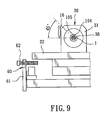
- the key coding member 50 includes a cylindrical terrace wheel 51 mounted rotatably on the work table 22, extending along the first transverse direction, and having a stepped end face that is provided with a plurality of successive steps 511 which are respectively formed with screw holes 512.
- the key coding member further includes a plurality of sector-shape block gauges 53 having various thicknesses, and a carriage holding member 52 that includes a post 522 mounted slidably on a guide rail 521 of the base 10, and a threaded holding rod projecting from a top end of the post 522 toward the terrace wheel 51.
- At least one of the block gauges 53 is selected to be detachably mounted on a selected one of the steps 511 (according to the code for cutting the key blank 1) via screw means 533 extending through the screw hole 512 in the selected step 511 and the screw hole 531 in the selected block gauge 53.
- the holding rod includes a threaded portion 523 adjustably mounted on the post 522 via screw means 524, and a holding pin 525 extending from the threaded portion 523 into a retaining hole 532 in the selected block gauge 53. Combinations of the block gauges and the steps 511 represent numerous cutting positions where the key blank 1 is to be cut.
- the terrace wheel 51 is turnable about a second axis that is parallel to the first axis to permit engagement of the threaded portion 523 and a selected one of the block gauges 53 so as to position the key blank 1 at a desired one of the cutting positions.
- the carriage holding member 52 is slidable along the guide rail 521 so as to be moved along with the terrace wheel 51 in the second transverse direction (X) when the carriage 20 moves along the same direction (X).
- a carriage stopper 54 is connected to the terrace wheel 51, and projects toward a side wall of the stand 14 so as to prevent further advancement of the carriage 20 when the carriage stopper 54 is moved along with the carriage 20 to contact the stand 14.
- the limiting member 60 includes a roatable circular plate 61 mounted on the carriage 20 and spaced apart long and short stoppers 62, 63 mounted adjustably on and projecting from the circular plate 61 toward a side wall of the work table 22 so as to prevent further advancement of the work table 22 when the side wall of the work table 22 is moved in the second transverse direction (X) to selectively abut against one of the long and short stoppers 62, 63.
- the cutting angle is less than 90° relative to the second grooved face 105 (see Figs.
- the long stopper 62 is turned to a position to be aligned with the side wall of the work table 22 via rotation of the circular plate 61, thereby preventing further advancement of the work table 22 when a center line of the key blank 1 reaches the milling tool 16.
- the short stopper 63 is turned to a position to be aligned with the side wall of the work table 22 via rotation of the circular plate 61 so as to prevent further advancement of the work table 22 after the entire cross-section of the key blank 1 passes through the milling tool 16.
- FIG. 7 and 12 to 15 An example of formation of three successive first, second and third indentations 106a, 106b, 106c in the second grooved faced 105 of the key blank 1 according to a code, i.e. using different combinations of the block gauges 53 and the steps 511 in the key coding member 50 for cutting the key blank 1, is illustrated in Figs. 7 and 12 to 15.
- a first block gauge 53a is mounted on a first step 511a of the stepped end face of the terrace wheel 51, and engages the threaded portion 523 of the holding rod to position the key blank 1 at a first position relative to the milling tool 16 where the first indentation 106a is to be formed.
- a second block gauge 53b is mounted on a second step 511b of the stepped end face of the terrace wheel 51 which is adjacent to the first step 511a, and engages the threaded portion 523 of the holding rod to position the key blank 1 at a second position relative to the milling tool 16 where a portion of the second indentation 106b is to be formed.
- the aforesaid first and second block gauges 53a, 53b have the same thickness (indicated as "W” in Figs. 12 and 13), and thus, the spacing (indicated as "d” in Fig. 13) between the first indentation 106a and the portion of the second indentation 106b is equal to the distance from the first step 511a to the second step 511b.
- a third block gauge 53c is mounted on a third step 511c of the stepped end face of the terrace wheel 51 which is adjacent to the second step 511b, and engages the threaded portion 523 of the holding rod to position the key blank 1 at a third position relative to the milling tool 16 where the remaining portion of the second indentation 106b is to be formed. It is noted that the cutting angle for the formation of the remaining portion of the second indentation 106b remains the same as that for the formation of the portion of the second indentation 106b in Fig. 13, and that the distance between each two adjacent steps 51 is equal to the value "d".
- the third block gauge 53c has a thickness (indicated as "W'" in Fig.
- a fourth block gauge 53d is mounted on a fourth step 511d of the stepped end face of the terrace wheel 51 which is adjacent to the third step 511c, and engages the threaded portion 523 of the holding rod to position the key blank 1 at a fourth position relative to the milling tool 16 where the third indentation 106c is to be formed.
- the aforesaid third and fourth block gauges 53c, 53d have the same thickness, thus, the spacing between the remaining portion of the second indentation 106b and the third indentation 106c is equal to the distance from the third step 511c to the fourth step 511d, i.e. equal to the value "d".
- the brushing member 17 includes a housing 173 formed with a plurality of key holes 171, and a brush 172 mounted movably in the housing 173 for cleaning the thus formed indentations 106 in the key blank 1.
Landscapes
- Engineering & Computer Science (AREA)
- Mechanical Engineering (AREA)
- Milling Processes (AREA)
Priority Applications (7)
| Application Number | Priority Date | Filing Date | Title |
|---|---|---|---|
| US09/730,094 US6413024B1 (en) | 2000-12-05 | 2000-12-05 | Key code cutting device |
| JP2000381735A JP3383286B2 (ja) | 2000-12-05 | 2000-12-15 | 歯切盤 |
| AU34401/02A AU770325B2 (en) | 2000-12-05 | 2002-04-18 | Key code cutting device |
| CA002382623A CA2382623C (en) | 2000-12-05 | 2002-04-18 | Key code cutting device |
| AT02252785T ATE305837T1 (de) | 2002-04-19 | 2002-04-19 | Vorrichtung zum schneiden einer schlüsselkode |
| EP02252785A EP1354654B1 (de) | 2000-12-05 | 2002-04-19 | Vorrichtung zum Schneiden einer Schlüsselkode |
| DE2002606471 DE60206471T2 (de) | 2002-04-19 | 2002-04-19 | Vorrichtung zum Schneiden eines Schlüsselkodes |
Applications Claiming Priority (5)
| Application Number | Priority Date | Filing Date | Title |
|---|---|---|---|
| US09/730,094 US6413024B1 (en) | 2000-12-05 | 2000-12-05 | Key code cutting device |
| JP2000381735A JP3383286B2 (ja) | 2000-12-05 | 2000-12-15 | 歯切盤 |
| AU34401/02A AU770325B2 (en) | 2000-12-05 | 2002-04-18 | Key code cutting device |
| CA002382623A CA2382623C (en) | 2000-12-05 | 2002-04-18 | Key code cutting device |
| EP02252785A EP1354654B1 (de) | 2000-12-05 | 2002-04-19 | Vorrichtung zum Schneiden einer Schlüsselkode |
Publications (2)
| Publication Number | Publication Date |
|---|---|
| EP1354654A1 true EP1354654A1 (de) | 2003-10-22 |
| EP1354654B1 EP1354654B1 (de) | 2005-10-05 |
Family
ID=32966731
Family Applications (1)
| Application Number | Title | Priority Date | Filing Date |
|---|---|---|---|
| EP02252785A Expired - Lifetime EP1354654B1 (de) | 2000-12-05 | 2002-04-19 | Vorrichtung zum Schneiden einer Schlüsselkode |
Country Status (5)
| Country | Link |
|---|---|
| US (1) | US6413024B1 (de) |
| EP (1) | EP1354654B1 (de) |
| JP (1) | JP3383286B2 (de) |
| AU (1) | AU770325B2 (de) |
| CA (1) | CA2382623C (de) |
Cited By (2)
| Publication number | Priority date | Publication date | Assignee | Title |
|---|---|---|---|---|
| EP1698429A1 (de) * | 2005-03-04 | 2006-09-06 | A.C.S. S.R.L. | System zur Schlüsselhandhabung für eine Schlüsselschneidmaschine |
| CN100360268C (zh) * | 2005-09-09 | 2008-01-09 | 吴鋆 | 钥匙坯自动刮背机 |
Families Citing this family (3)
| Publication number | Priority date | Publication date | Assignee | Title |
|---|---|---|---|---|
| SE537788C2 (sv) * | 2012-07-18 | 2015-10-20 | Winloc Ag | Sätt och apparat för framställning av ett profilspår i ett nyckelämne |
| CN108788257B (zh) * | 2018-07-26 | 2024-02-20 | 丹江口市东明工贸有限公司 | 一种用于汽车钥匙的双面铣槽机 |
| CN110560766B (zh) * | 2019-08-30 | 2024-05-17 | 曹县精锐机械锁业有限公司 | 自动钥匙双面铣槽机 |
Citations (4)
| Publication number | Priority date | Publication date | Assignee | Title |
|---|---|---|---|---|
| DE7207289U (de) * | 1972-06-22 | Boerkey A | Kopiereinrichtung zum Herstellen der Schlusselprofile von Ersatzschlusseln | |
| US4325662A (en) * | 1980-04-04 | 1982-04-20 | Henry Bartos | Tubular key cutting machine |
| DE7702315U1 (de) * | 1974-10-03 | 1985-10-03 | Eilebrecht, Dietmar | Schlüsselfräsmaschine |
| US4671711A (en) * | 1983-12-05 | 1987-06-09 | Chicago Lock Co. | Key-cutting machine |
Family Cites Families (10)
| Publication number | Priority date | Publication date | Assignee | Title |
|---|---|---|---|---|
| DE2700114C3 (de) * | 1977-01-04 | 1979-08-23 | August Boerkey Nachf., 5820 Gevelsberg | Schliisselkopiermaschine |
| US4324513A (en) * | 1980-02-08 | 1982-04-13 | Hughes Donald R | Tubular key manufacturing machine |
| US4373414A (en) * | 1980-10-06 | 1983-02-15 | Agius Frank P | Coded key cutting device |
| US4526498A (en) * | 1981-07-30 | 1985-07-02 | Lloyd Matheson, Inc. | Key forming machine |
| US4411567A (en) * | 1981-09-14 | 1983-10-25 | Agius Frank P | Tubular key cutting machine |
| FI822535L (fi) * | 1982-07-19 | 1984-01-20 | Waertsilae Oy Ab | Kopplings- och oeverfoeringsmekanism |
| DE3346689A1 (de) * | 1983-12-23 | 1985-07-04 | Aug. Bremicker Söhne KG, 5802 Wetter | Schluesselfraesmaschine |
| US4657448A (en) * | 1985-04-29 | 1987-04-14 | Arthur Alexander | Pantograph angular bitted key cutting machine |
| IT1205075B (it) * | 1987-06-23 | 1989-03-10 | Mec Giuseppe Bollini Di Sergio | Dispositivo adattatore per macchine duplicatrici di chiavi |
| JPH0419007A (ja) * | 1990-05-09 | 1992-01-23 | Kuroobaa:Kk | 鍵切削装置 |
-
2000
- 2000-12-05 US US09/730,094 patent/US6413024B1/en not_active Expired - Fee Related
- 2000-12-15 JP JP2000381735A patent/JP3383286B2/ja not_active Expired - Fee Related
-
2002
- 2002-04-18 AU AU34401/02A patent/AU770325B2/en not_active Ceased
- 2002-04-18 CA CA002382623A patent/CA2382623C/en not_active Expired - Fee Related
- 2002-04-19 EP EP02252785A patent/EP1354654B1/de not_active Expired - Lifetime
Patent Citations (4)
| Publication number | Priority date | Publication date | Assignee | Title |
|---|---|---|---|---|
| DE7207289U (de) * | 1972-06-22 | Boerkey A | Kopiereinrichtung zum Herstellen der Schlusselprofile von Ersatzschlusseln | |
| DE7702315U1 (de) * | 1974-10-03 | 1985-10-03 | Eilebrecht, Dietmar | Schlüsselfräsmaschine |
| US4325662A (en) * | 1980-04-04 | 1982-04-20 | Henry Bartos | Tubular key cutting machine |
| US4671711A (en) * | 1983-12-05 | 1987-06-09 | Chicago Lock Co. | Key-cutting machine |
Cited By (2)
| Publication number | Priority date | Publication date | Assignee | Title |
|---|---|---|---|---|
| EP1698429A1 (de) * | 2005-03-04 | 2006-09-06 | A.C.S. S.R.L. | System zur Schlüsselhandhabung für eine Schlüsselschneidmaschine |
| CN100360268C (zh) * | 2005-09-09 | 2008-01-09 | 吴鋆 | 钥匙坯自动刮背机 |
Also Published As
| Publication number | Publication date |
|---|---|
| CA2382623C (en) | 2006-02-07 |
| US6413024B1 (en) | 2002-07-02 |
| AU3440102A (en) | 2003-10-23 |
| JP3383286B2 (ja) | 2003-03-04 |
| EP1354654B1 (de) | 2005-10-05 |
| AU770325B2 (en) | 2004-02-19 |
| US20020067967A1 (en) | 2002-06-06 |
| JP2002205215A (ja) | 2002-07-23 |
| CA2382623A1 (en) | 2003-10-18 |
Similar Documents
| Publication | Publication Date | Title |
|---|---|---|
| US4685496A (en) | Accessory tool for hand routers | |
| CN1165063A (zh) | 用于滑动组合斜角锯的斜面锁定机构 | |
| CN210678996U (zh) | 一种台锯结构 | |
| EP1354654B1 (de) | Vorrichtung zum Schneiden einer Schlüsselkode | |
| AU2016200004A1 (en) | Saw with circular blade | |
| CN201808103U (zh) | 台式圆盘锯用夹具及台式圆盘锯 | |
| ES2917148T3 (es) | Fresadora manual portátil para realizar cavidades en una superficie de un tablero | |
| US6293177B1 (en) | Workpiece positioning device | |
| EP0032476A2 (de) | Schraubstock mit verschiedenen maximalen Öffnungskapazitäten und mit verschiedenen Spannwirkungen | |
| EP1690622A2 (de) | Kraftgetriebene Sägevorrichtung | |
| US20150034210A1 (en) | Router Guide | |
| CN1351914A (zh) | 刻齿机 | |
| JP2589346Y2 (ja) | 鍵切り盤 | |
| DE60206471T2 (de) | Vorrichtung zum Schneiden eines Schlüsselkodes | |
| CN2159842Y (zh) | 手弓锯辅助锯切装置 | |
| US2519269A (en) | Saw guide with adjustable work clamp | |
| US9021928B2 (en) | Lathe accessory for band saw | |
| AU2004222725B2 (en) | Clamping device for key duplicating machine with replaceable segmented jaws | |
| US3938796A (en) | Workpiece location apparatus | |
| AU2014100847A4 (en) | Powered saw apparatus | |
| JP2008055702A (ja) | 切断機用案内装置 | |
| KR200308363Y1 (ko) | 멀티기계톱 | |
| JPS6228403Y2 (de) | ||
| JPH0531903U (ja) | ほぞ切り機のバイス装置 | |
| JPS6134963B2 (de) |
Legal Events
| Date | Code | Title | Description |
|---|---|---|---|
| PUAI | Public reference made under article 153(3) epc to a published international application that has entered the european phase |
Free format text: ORIGINAL CODE: 0009012 |
|
| AK | Designated contracting states |
Kind code of ref document: A1 Designated state(s): AT BE CH CY DE DK ES FI FR GB GR IE IT LI LU MC NL PT SE TR |
|
| AX | Request for extension of the european patent |
Extension state: AL LT LV MK RO SI |
|
| 17P | Request for examination filed |
Effective date: 20040420 |
|
| AKX | Designation fees paid |
Designated state(s): AT BE CH CY DE DK ES FI FR GB GR IE IT LI LU MC NL PT SE TR |
|
| AXX | Extension fees paid |
Extension state: RO Payment date: 20040420 Extension state: LT Payment date: 20040420 |
|
| 17Q | First examination report despatched |
Effective date: 20041011 |
|
| GRAP | Despatch of communication of intention to grant a patent |
Free format text: ORIGINAL CODE: EPIDOSNIGR1 |
|
| GRAS | Grant fee paid |
Free format text: ORIGINAL CODE: EPIDOSNIGR3 |
|
| GRAA | (expected) grant |
Free format text: ORIGINAL CODE: 0009210 |
|
| AK | Designated contracting states |
Kind code of ref document: B1 Designated state(s): AT BE CH CY DE DK ES FI FR GB GR IE IT LI LU MC NL PT SE TR |
|
| AX | Request for extension of the european patent |
Extension state: LT RO |
|
| PG25 | Lapsed in a contracting state [announced via postgrant information from national office to epo] |
Ref country code: CH Free format text: LAPSE BECAUSE OF FAILURE TO SUBMIT A TRANSLATION OF THE DESCRIPTION OR TO PAY THE FEE WITHIN THE PRESCRIBED TIME-LIMIT Effective date: 20051005 Ref country code: IT Free format text: LAPSE BECAUSE OF FAILURE TO SUBMIT A TRANSLATION OF THE DESCRIPTION OR TO PAY THE FEE WITHIN THE PRESCRIBED TIME-LIMIT;WARNING: LAPSES OF ITALIAN PATENTS WITH EFFECTIVE DATE BEFORE 2007 MAY HAVE OCCURRED AT ANY TIME BEFORE 2007. THE CORRECT EFFECTIVE DATE MAY BE DIFFERENT FROM THE ONE RECORDED. Effective date: 20051005 Ref country code: BE Free format text: LAPSE BECAUSE OF FAILURE TO SUBMIT A TRANSLATION OF THE DESCRIPTION OR TO PAY THE FEE WITHIN THE PRESCRIBED TIME-LIMIT Effective date: 20051005 Ref country code: NL Free format text: LAPSE BECAUSE OF FAILURE TO SUBMIT A TRANSLATION OF THE DESCRIPTION OR TO PAY THE FEE WITHIN THE PRESCRIBED TIME-LIMIT Effective date: 20051005 Ref country code: FI Free format text: LAPSE BECAUSE OF FAILURE TO SUBMIT A TRANSLATION OF THE DESCRIPTION OR TO PAY THE FEE WITHIN THE PRESCRIBED TIME-LIMIT Effective date: 20051005 Ref country code: AT Free format text: LAPSE BECAUSE OF FAILURE TO SUBMIT A TRANSLATION OF THE DESCRIPTION OR TO PAY THE FEE WITHIN THE PRESCRIBED TIME-LIMIT Effective date: 20051005 Ref country code: LI Free format text: LAPSE BECAUSE OF FAILURE TO SUBMIT A TRANSLATION OF THE DESCRIPTION OR TO PAY THE FEE WITHIN THE PRESCRIBED TIME-LIMIT Effective date: 20051005 |
|
| REG | Reference to a national code |
Ref country code: GB Ref legal event code: FG4D |
|
| REG | Reference to a national code |
Ref country code: CH Ref legal event code: EP |
|
| REG | Reference to a national code |
Ref country code: IE Ref legal event code: FG4D |
|
| REF | Corresponds to: |
Ref document number: 60206471 Country of ref document: DE Date of ref document: 20051110 Kind code of ref document: P |
|
| PG25 | Lapsed in a contracting state [announced via postgrant information from national office to epo] |
Ref country code: SE Free format text: LAPSE BECAUSE OF FAILURE TO SUBMIT A TRANSLATION OF THE DESCRIPTION OR TO PAY THE FEE WITHIN THE PRESCRIBED TIME-LIMIT Effective date: 20060105 Ref country code: DK Free format text: LAPSE BECAUSE OF FAILURE TO SUBMIT A TRANSLATION OF THE DESCRIPTION OR TO PAY THE FEE WITHIN THE PRESCRIBED TIME-LIMIT Effective date: 20060105 Ref country code: GR Free format text: LAPSE BECAUSE OF FAILURE TO SUBMIT A TRANSLATION OF THE DESCRIPTION OR TO PAY THE FEE WITHIN THE PRESCRIBED TIME-LIMIT Effective date: 20060105 |
|
| PG25 | Lapsed in a contracting state [announced via postgrant information from national office to epo] |
Ref country code: ES Free format text: LAPSE BECAUSE OF FAILURE TO SUBMIT A TRANSLATION OF THE DESCRIPTION OR TO PAY THE FEE WITHIN THE PRESCRIBED TIME-LIMIT Effective date: 20060116 |
|
| NLV1 | Nl: lapsed or annulled due to failure to fulfill the requirements of art. 29p and 29m of the patents act | ||
| PG25 | Lapsed in a contracting state [announced via postgrant information from national office to epo] |
Ref country code: PT Free format text: LAPSE BECAUSE OF FAILURE TO SUBMIT A TRANSLATION OF THE DESCRIPTION OR TO PAY THE FEE WITHIN THE PRESCRIBED TIME-LIMIT Effective date: 20060306 |
|
| LTIE | Lt: invalidation of european patent or patent extension |
Effective date: 20051005 |
|
| REG | Reference to a national code |
Ref country code: CH Ref legal event code: PL |
|
| PG25 | Lapsed in a contracting state [announced via postgrant information from national office to epo] |
Ref country code: IE Free format text: LAPSE BECAUSE OF NON-PAYMENT OF DUE FEES Effective date: 20060419 |
|
| PGFP | Annual fee paid to national office [announced via postgrant information from national office to epo] |
Ref country code: GB Payment date: 20060421 Year of fee payment: 5 |
|
| PGFP | Annual fee paid to national office [announced via postgrant information from national office to epo] |
Ref country code: FR Payment date: 20060424 Year of fee payment: 5 |
|
| PG25 | Lapsed in a contracting state [announced via postgrant information from national office to epo] |
Ref country code: MC Free format text: LAPSE BECAUSE OF NON-PAYMENT OF DUE FEES Effective date: 20060430 |
|
| ET | Fr: translation filed | ||
| PGFP | Annual fee paid to national office [announced via postgrant information from national office to epo] |
Ref country code: DE Payment date: 20060616 Year of fee payment: 5 |
|
| PLBE | No opposition filed within time limit |
Free format text: ORIGINAL CODE: 0009261 |
|
| STAA | Information on the status of an ep patent application or granted ep patent |
Free format text: STATUS: NO OPPOSITION FILED WITHIN TIME LIMIT |
|
| 26N | No opposition filed |
Effective date: 20060706 |
|
| REG | Reference to a national code |
Ref country code: IE Ref legal event code: MM4A |
|
| GBPC | Gb: european patent ceased through non-payment of renewal fee |
Effective date: 20070419 |
|
| PG25 | Lapsed in a contracting state [announced via postgrant information from national office to epo] |
Ref country code: DE Free format text: LAPSE BECAUSE OF NON-PAYMENT OF DUE FEES Effective date: 20071101 |
|
| PG25 | Lapsed in a contracting state [announced via postgrant information from national office to epo] |
Ref country code: GB Free format text: LAPSE BECAUSE OF NON-PAYMENT OF DUE FEES Effective date: 20070419 |
|
| PG25 | Lapsed in a contracting state [announced via postgrant information from national office to epo] |
Ref country code: FR Free format text: LAPSE BECAUSE OF NON-PAYMENT OF DUE FEES Effective date: 20070430 Ref country code: TR Free format text: LAPSE BECAUSE OF FAILURE TO SUBMIT A TRANSLATION OF THE DESCRIPTION OR TO PAY THE FEE WITHIN THE PRESCRIBED TIME-LIMIT Effective date: 20051005 Ref country code: LU Free format text: LAPSE BECAUSE OF NON-PAYMENT OF DUE FEES Effective date: 20060419 |
|
| PG25 | Lapsed in a contracting state [announced via postgrant information from national office to epo] |
Ref country code: CY Free format text: LAPSE BECAUSE OF FAILURE TO SUBMIT A TRANSLATION OF THE DESCRIPTION OR TO PAY THE FEE WITHIN THE PRESCRIBED TIME-LIMIT Effective date: 20051005 |