EP1354802A2 - Faltbare Kunststoff-Flasche - Google Patents
Faltbare Kunststoff-Flasche Download PDFInfo
- Publication number
- EP1354802A2 EP1354802A2 EP02016180A EP02016180A EP1354802A2 EP 1354802 A2 EP1354802 A2 EP 1354802A2 EP 02016180 A EP02016180 A EP 02016180A EP 02016180 A EP02016180 A EP 02016180A EP 1354802 A2 EP1354802 A2 EP 1354802A2
- Authority
- EP
- European Patent Office
- Prior art keywords
- container
- main body
- container main
- bellows
- approximately
- Prior art date
- Legal status (The legal status is an assumption and is not a legal conclusion. Google has not performed a legal analysis and makes no representation as to the accuracy of the status listed.)
- Withdrawn
Links
Images





Classifications
-
- B—PERFORMING OPERATIONS; TRANSPORTING
- B65—CONVEYING; PACKING; STORING; HANDLING THIN OR FILAMENTARY MATERIAL
- B65D—CONTAINERS FOR STORAGE OR TRANSPORT OF ARTICLES OR MATERIALS, e.g. BAGS, BARRELS, BOTTLES, BOXES, CANS, CARTONS, CRATES, DRUMS, JARS, TANKS, HOPPERS, FORWARDING CONTAINERS; ACCESSORIES, CLOSURES, OR FITTINGS THEREFOR; PACKAGING ELEMENTS; PACKAGES
- B65D1/00—Rigid or semi-rigid containers having bodies formed in one piece, e.g. by casting metallic material, by moulding plastics, by blowing vitreous material, by throwing ceramic material, by moulding pulped fibrous material or by deep-drawing operations performed on sheet material
- B65D1/02—Bottles or similar containers with necks or like restricted apertures, designed for pouring contents
- B65D1/0223—Bottles or similar containers with necks or like restricted apertures, designed for pouring contents characterised by shape
- B65D1/0292—Foldable bottles
Definitions
- the present invention relates to improvements in a container for juice or mineral water which is constructed using a blow molding process or the like, and in particular, to a container that is compressed in a longitudinal direction thereof (i.e., the volume is decreased) when emptied.
- synthetic resin bottles of this kind can be manufactured using simple means such as blow molding, they are not strong enough to be transported using automobiles or other transportation means, which are subject to violent shaking or vibration, or to be stacked at stores for display.
- the inventor has already proposed a container whose volume can be significantly reduced when a user drinks all the juice or mineral water in a container main body and disposes of the empty container, to allow increased numbers of container main bodies to be accommodated in garbage cans.
- the present invention improves the above container. It is an object of the present invention to provide a container that can be easily and manually compressed when empty, so as significantly to reduce the container dimensions, in particular, container height by compression, and can maintain its compressed state without the need to place a cap thereon.
- the object of the present invention is to allow the volume of a container to be significantly reduced when the empty container is to be disposed of or the container is to be transported.
- this compressed state can be maintained for extended periods or until the container main body is crushed or dissolved for recycling, without the need to apply recovery force to the container main body.
- the present invention provides a container main body that has a sufficiently attractive external shape to interest users when used as a drink container, and which can maintain a compressed state along a longitudinal direction thereof to prevent slipping or falling during use and prevent the contents thereof from overflowing, as well as a method of compressing the container main body in the longitudinal direction thereof.
- the present invention is characterized in that when a predominantly right-angle force is applied to a bellows-shaped portion of the container main body, a unidirectional force acts on one of the folds constituting the bellows-shaped portion and/or part of an inner circumference of the fold, while an opposite force acts on an outer circumference thereof, thereby maintaining a bellows shape that is compressed in a longitudinal direction.
- the present invention is also characterized in that the bellows-shaped portion of the container main body is shaped so that the diameter of one side thereof is smaller than that of the other side.
- the present invention is also characterized in that the bellows-shaped portion of the container main body is shaped so that the diameter of one side thereof is smaller than that of the other side and that the diameter of the bellows-shaped portion increases sequentially from one side toward the other side and is comparable to the diameter of the bottom of the container main body.
- the present invention is also characterized in that the general shape of the container main body is appropriately selected from a group consisting of cylinders including ellipses, prisms including rectangles, cones or pyramids including truncations, hourglass drum shapes, and barrel shapes.
- the present invention is also characterized in that the shape of a horizontal cross section of the container main body is appropriately selected from a group consisting of circles including ellipses and prisms including rectangles.
- the present invention is also characterized in that the container main body has a label wrapped around an outer circumference thereof with a notice about or a trademark for contents of the container.
- the present invention provides a container comprising a container main body having a tap portion projecting upward from a central portion of an upper end and a bellows-shaped portion formed in inner and outer walls of the container main body over the entire longitudinal length thereof, or over a part of the longitudinal length, except for the tap portion, the bellows-shaped portion having horizontally extending folds, the diameter of the bellows-shaped portion being smaller in an upper part thereof than in a lower part thereof and increasing from the upper part to the lower part, the container being characterized in that when a predominantly right-angle force is applied to the bellows-shaped portion of the container main body, a downward force acts on an inner diameter direction of the upper folds of the bellows-shaped portion, while an upward force acts on an outer diameter direction thereof, and an upward force acts on an inner diameter direction of lower folds of the bellows-shaped portion, while an upward and downward forces act on an outer diameter direction thereof, thereby maintaining a compressed bellows shape to reduce the length (height) of the container main body.
- the present invention provides a container comprising a bellows-shaped portion formed over the entire longitudinal length thereof, or over a part of the longitudinal length, except for a tap portion, the container being characterized in that a connection between the tap portion and a rear portion of a top surface of a container main body is bent to project downward, and when a predominantly right-angle force is applied to the bellows-shaped portion, all or part of the tap portion can be folded into the container main body using the bent portion as a base point, and in that a unidirectional force acts on one of the folds constituting the bellows-shaped portion and/or part of an inner circumference of the fold, while an opposite force acts on an outer circumference thereof, thereby maintaining a bellows shape that is compressed in a longitudinal direction.
- the present invention is also characterized in that the bent portion projects downward and has a radius of curvature of 3 to 10 mmR, and is drawn or reversed to push part or all of the tap portion into the container main body when the container main body is compressed, thereby maintaining the state in which the container is compressed in the longitudinal direction thereof.
- the present invention is also characterized in that the connection between the tap portion and the container main body is shaped like a trumpet, having height at least half that of the tap portion of the container main body, and is reversed to push part or all of the tap portion into the container main body when the container main body is compressed, thereby maintaining the state in which the container is compressed in the longitudinal direction thereof.
- the present invention is also characterized in that the container main body is formed as a bellows-shaped portion extending over the entire longitudinal length thereof or over a part of the longitudinal length and has horizontally-extending or spiral folds.
- a predominantly right-angle force is applied to the bellows-shaped portion of the container main body, a force is exerted to unidirectionally push one of the folds constituting the bellows-shaped portion and/or part of an inner circumference of the fold, while an opposite force acts on an outer circumference thereof, thereby maintaining a bellows shape that is compressed in a longitudinal direction thereof.
- the present invention is characterized in that the container main body has the size that of a typical container called a "PET bottle (mini bottle)" and having a volume of 500 ml, at least a first fold has an outer diameter of approximately 60.5 mm and a second fold has an outer diameter of approximately 68 mm, and a portion between the first and second folds has an inner diameter of approximately 47 mm; in that a third fold has an outer diameter of approximately 70 mm and a portion between the second and third folds has an inner diameter of approximately 51 mm, the inner diameter increasing sequentially; and in that the container main body typically has an outer diameter of approximately 71.5 mm and an inner diameter of approximately 54.5 mm, as well as three to six upper folds, and typically has a total of 10 to 15 folds, thereby maintaining a shape that is compressed in a longitudinal direction of the container.
- PET bottle mini bottle
- each fold is divided into upper and lower portions by a horizontal line and is shaped like an unidentified flying object (UFO) known as the "Adamski type," whereby the upper and lower portions of the first fold have heights of approximately 6.5 mm and 5.5 mm, respectively, the upper and lower portions of the second fold have heights of approximately 7 mm and approximately 5 mm, respectively, and the upper and lower portions of the third fold have heights of approximately 8.5 mm and approximately 6.5 mm, respectively, with the width of the folds increasing sequentially; and in that a top surface of the bead-on-abacus shape projects outward to form a bay-like shape having a radius of curvature of approximately 20 mmR, whereas a bottom surface thereof is shaped like a straight line following a projecting arc having a radius of curvature of approximately 0.8 mmR, thereby maintaining the state in which the container is compressed in the longitudinal direction thereof.
- UFO unidentified flying object
- the present invention is also characterized in that the bent portion of the rear portion of the container main body is shaped to project downward to have a radius of curvature of 3 to 10 mmR and is drawn or reversed to push part or all of the tap portion into the container main body when the container main body is compressed; and in that the trumpet-shaped connection of the container main body has a height at least half that of the tap portion of the container main body and is reversed to push part or all of the tap portion into the container main body when the container main body is compressed.
- the present invention is also characterized in that the container main body has a bellows-shaped portion formed over the entire longitudinal length thereof or over a part of the longitudinal length and has horizontally-extending or spiral folds, and a top surface of each of the folds constituting the bellows-shaped portion is shaped like an arc, and a bottom surface connecting to the top surface is shaped substantially like a straight line, thereby maintaining the state in which the container is compressed in the longitudinal direction thereof.
- each fold is divided into upper and lower portions by a horizontal line and is shaped like a UFO known as the "Adamski type," whereby the upper and lower portions of the first fold have heights of approximately 6.5 mm and 5.5 mm, respectively, the upper and lower portions of the second fold have heights of approximately 7 mm and approximately 5 mm, respectively, and the upper and lower portions of the third fold have heights of approximately 8.5 mm and approximately 6.5 mm, respectively, with the width of the folds increasing sequentially; and in that a top surface of this bead-on-abacus shape projects outward to form a bay-like shape having a radius of curvature of approximately 20 mmR, whereas a bottom surface thereof is shaped like a straight line following a projecting arc having a radius of curvature of approximately 0.8 mmR.
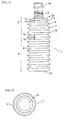
- reference numeral 1 denotes a container main body comprising a bellows-shaped portion (2) in outer and inner circumferences thereof in a height (length) direction thereof.
- Figs. 3, 4, and 20 show that mineral water is contained in the container main body (1).
- a user drinks all the mineral water and compresses the container main body in the height (longitudinal) direction from one or both sides thereof. That is, the present invention has excellent construction and effects to compress the container main body (1) and maintain a compressed state.
- reference numeral (3) denotes a tap portion of the container main body (1), which is externally threaded in an outer circumference thereof and has a diameter of approximately 28 mm and a height of 23 mm.
- a trumpet-shaped connection (D) is arranged immediately below the tap portion (3) and connected thereto on the axis thereof.
- the trumpet-shaped connection (D) includes a bottom portion having an increased diameter of approximately 51 mm and has a height of 5 to 10 mm.
- the container main body (1) comprises a shoulder (C) having a "U" shaped annular groove (E) with a horizontal inner end. As shown in Fig. 21, a terminal of the trumpet-shaped connection (D) is connected to an inner side of the annular groove (E).
- an outer side of the U-shaped groove (E) constitutes a blastomere-shaped portion (4) extending outward.
- a first fold (5) of a bellows-shaped portion has an outer diameter (the highest fold of the bellows-shaped portion (2)) (d1) smaller than the outer diameter (d) of the container main body.
- a second fold (6) has an outer diameter (d2) larger than the outer diameter (d1) of the first fold (5) and smaller than the outer diameter (d) of the container main body.
- a third fold (7) has an outer diameter (d3) larger than the outer diameter (d2) of the second fold (6) and smaller than the outer diameter (d) of the container main body.
- the container main body looks like a stairway when viewed from the side.
- the number of folds is not limited to three as described above, but may be an arbitrary plural number. In the embodiment shown in Fig. 1, four folds are shown.
- the main body (1) of the container in Fig. 1 has a height of 195 mm, a maximum diameter of approximately 71.5 mm, and a volume of 500 ml, as well as 12 folds.
- the first fold (5) of the bellows-shaped portion has an outer diameter (d1) of 60.5 mm.
- the second fold (6) of the bellows-shaped portion has an outer diameter (d2) of 67.9 mm.
- the portion between the first and second folds (5) and (6) of the bellows-shaped portion has an inner diameter of 47 mm.
- the third fold (7) of the bellows-shaped portion has an outer diameter (d3) of 69.7 mm.
- the portion between the second and third folds (6) and (7) of the bellows-shaped portion has an inner diameter of 51.1 mm.
- a fourth fold (8) of the bellows-shaped portion has an outer diameter (d) equal to the largest outer diameter of the container main body (1), i.e., 71.5 mm.
- the portion between the third and fourth folds (7) and (8) of the bellows-shaped portion has an inner diameter of 54.5 mm.
- the following fifth to twelfth folds of the bellows-shaped portion each have the same outer diameter as that (d) of the fourth fold (8).
- the portion between each pair of folds within this range has the same inner diameter as that of the portion between the third and fourth folds (7) and (8).
- each fold is shaped like a UFO known as the "Adamski type" and is thus divided into upper and lower portions by a horizontal line.
- the upper and lower portions (h1 and h2) of the first fold have heights of 6.5 mm and 5.5 mm, respectively.
- the upper and lower portions of the second fold have heights of 7 mm and 5 mm, respectively.
- the upper and lower portions of the third fold have heights of 8.5 mm and 6.5 mm, respectively.
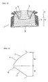
- FIG. 5 shows the sectional shape of these folds. That is, this example shows the dimensions of the first to third folds (5) to (7).
- a top surface (20) of the wide bead-on-abacus-like shape (9) is formed like a bay projecting outward and having a radius of curvature of 20 mmR in this embodiment.
- a bottom surface (21) thereof is shaped like a straight line (11) following a projecting arc (10) having a radius of curvature of 0.8 mmR.
- the container main body (1) is divided into a shell (A) including a central portion and a bottom portion, and a shoulder (C) located above.
- the shell (A) and shoulder (C) each have two diameters, a larger and a smaller diameter, thus serving to maintain a stable vertical state.
- the shell (A), including the central portion and the bottom portion, has its inner and outer diameters formed by the same fold.
- the shoulder (C) is bent and gently inclined to form the projecting tap portion (3).
- troughs (18) forming the folds have an inner diameter gradually decreasing and have larger differences in inclination between themselves than in the shell (A).
- the inner diameters and inclined surfaces of crests (17) and the troughs (18) forming the folds serve to maintain an extended state on the basis of the strength and elasticity of material for the container.
- a bottom surface (B) is recessed to have a steep inclination, the container can be stably placed on a level surface.
- a commercially available container main body (1) is provided with a cap (14).
- a user removes the cap (14), drinks all the contents of the container, and then presses the tap portion (3).
- the shoulder (C) and the shell (A) are compressed and contracted, as shown in Figs. 3 and 20.
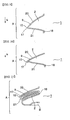
- one of the folds of the shoulder (C) is pressed to cause the end surface of the corresponding trough (18) to compress the end surface of the trough of the vertically adjacent fold.
- both troughs (18) are pressed toward the vertices of the crests 17, as shown in Figs. 7 and 8.
- the inner diameter of the crest (17) constituting the fold is increased owing to pressure, or the inner diameter of the trough (18) is reduced owing to compressing pressure.
- the steeply inclined surface of the bottom surface (21) constituting the fold is bent.
- the steeply inclined bottom surface passes immediately below the crest (17) and then slips to the inside of the gently inclined top surface (20).
- the bottom surface is moved until the height of the container main body (1) is sufficiently reduced.
- force is exerted to restore the inner diameters of the crests (17) and troughs (18), or the bottom surface (21), which has been bent through the above operation, is restored to its extended state.
- a stable state is established. Therefore, this compressed state can be maintained without always applying compressive force.
- the troughs (18) are subjected to compressive pressure to further reduce their inner diameters. Consequently, pressure stress is generated.
- compressive pressure is eliminated, the stress is relaxed to restore the troughs to their extended state.
- the user then puts the cap (14) on the container under pressure to allow atmospheric pressure to act on the container.
- the container main body (1) maintains the compressed state. This state is maintained unless compressive stress is generated owing to a difference in inner diameter between the troughs (18).
- the container main body (1) had its height (volume) reduced to one-third to one-fourth.
- the container main bodies were accommodated in a garbage can or the like, they occupied significantly less space.
- the tap portion (3) in the state established through the above operation, is further pressed toward the bottom surface (B) of the container main body. At this time, the shell (A) and the shoulder (C) have their folds tightly contacted with one another, further pressing does not cause them to lower.
- the terminal side of the trumpet-shaped connection (D) presses the inside of the U-shaped groove (E) downward. Since the outer upper end side of the groove (E) is connected and secured to the shoulder (C), the U-shape is collapsed in such a manner that the inside of the groove is pushed downward. Thus, a terminal portion of the trumpet-shaped connection (D) is pressed downward and enlarged.
- the connection (D) is pushed into the container main body (1) together with the tap portion (3).
- the container main body (1) when the container main body (1) is disposed of, it is compact and has a height approximately one-fifth that of the original container main body (1). That is, the volume of the container main body (1) can be significantly reduced.
- connection (D) between the tap portion (3) and the container main body (1) is shaped like a trumpet.
- the connection (D) is reversed and fitted into the container main body (1).
- the tap portion (3) can have its height (volume) sufficiently reduced without being forcibly pushed into the compressed container main body (1).
- the folds of the container main body (1) are each shaped like a wide Adamski-type UFO and are thus divided into upper and lower portions.
- the upper and lower portions (h1 and h2) of the first fold have heights of 6.5 mm and 5.5 mm, respectively.
- the upper and lower portions of the second fold have heights of 7 mm and 5 mm, respectively.
- the upper and lower portions of the third fold have heights of 8.5 mm and 6.5 mm, respectively.
- Figs. 9 to 11 show an example of the dimensions of each fold of the 4-fold bellows-shaped portion (8) and 12-fold bellows-shaped portion, i.e., the heights of the upper and lower portions (hx and hy) of the fold shown in Fig. 5. All folds have the same shape.
- reference numeral (20) denotes a top surface of the wide Adamski-type UFO-shaped fold, including an inner surface thereof.
- Reference numeral (21) denotes a bottom surface of the wide Adamski-type UFO-shaped fold including an inner surface thereof.
- the top surface (20) is shaped to project outward to have a radius of curvature of 20 mmR in this embodiment.
- the bottom surface (21) is shaped like a straight line following a projecting arc (10) having a radius of curvature of 0.8 mmR.
- a commercially available container main body (1) is provided with a cap (14).
- a user removes the cap (14), drinks all the contents of the container, and then presses the tap portion (3).
- the shoulder (C) and the shell (A) are compressed and contracted as shown in Figs. 3 and 20.
- one of the folds of the shoulder (C) is pressed to cause the end surface of the corresponding trough (18) to compress the end surface of the trough of the vertically adjacent fold, as shown in Figs. 9 to 11.
- both troughs (18) are pressed toward the vertices of the crests (17), as shown in Figs. 10 and 11.
- the inner diameter of the crest (17) constituting the fold is increased owing to enlarging pressure, or the inner diameter of the trough (18) is reduced owing to compressing pressure.
- the steeply inclined surface of the bottom surface (21) constituting the fold is bent.
- the steeply inclined bottom surface passes immediately below the crest (17) and slips to the inside of the gently inclined top surface (20), as shown in Figs. 10 and 11.
- the bottom surface is moved until the height of the container main body (1) is sufficiently reduced.
- Force is then exerted to restore the inner diameters of the crests (17) and troughs (18), or the bottom surface (21), which has been bent through the above operation, is restored to its extended state.
- This compressed state can be maintained without always applying compressive force.
- the troughs (18) are subjected to compressive pressure. Consequently, pressure stress is generated.
- the compressive pressure is eliminated, the stress is relaxed to restore the troughs to their extended state.
- the user then puts the cap (14) on the container under pressure to allow atmospheric pressure to act on the container.
- the container main body (1) then maintains the compressed state. This state is maintained unless compressive stress is generated owing to a difference in inner diameter between the troughs (18).
- lower folds of the shoulder (C) of the container main body (1) have larger diameters, as described previously.
- the compressed folds are pressed against one another and inclined so that their outer periphery lies above their inner periphery.
- the blastomere-shaped portion (4) and bay-shaped portion (9) forming an upper inclined portion of each fold of the shoulder portion (C) are "balanced" with respect to a lower inclined portion of each folds of the shell (A).
- the container main body (1) can maintain its compressed state without requiring the placement of a cap (14) on the tap portion.
- the container main body (1) is shaped externally like a cylinder or cylinder analog.
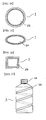
- the container main body (1) is shaped like an hourglass drum (22), as shown in Figs. 12 and 13, the main body (1) can be grasped more easily.
- the container main body (1) is shaped like a truncated cone or pyramid, it is more stable. It has thus been found that an appropriate external shape can be freely selected.
- the horizontal sectional shape of the container main body (1) is not limited to a circle (23) but may be freely selected. For example, it may be an ellipse (24) or a square (25).
- the bellows-shaped portion (2) formed in the container main body (1) comprises annular folds connected vertically, with each fold extending horizontally.
- the bellows-shaped portion (2) comprises a continuous spiral (26), as shown in Fig. 17, the container main body (1) is more easily compressed. This is because the container main body (1) is subjected not just to vertical force and pressed upward or toward the center thereof, but is twisted.
- This spiral (26) may comprise one or more pieces.
- the spiral (26) need not be continuous, but may be discontinuous (26), as shown in Fig. 18, or may comprise slightly inclined straight lines (26), as shown in Fig. 19.
- the container main body (1) has a bellows-shaped portion (2) formed over the entire vertical length.
- the container main body (1) includes a flat portion in the middle thereof, or at a terminal thereof, to permit placement of a trademark or description of contents.
- the main effect of the present invention is a significant reduction in the volume occupied by the container main body at disposal, thereby increasing the number of container main bodies that can be accommodated in a garbage can or like vessel.
- Such a compressed container main body makes it possible to transport large numbers of containers simultaneously, reducing the costs associated with cleaning and collecting empty containers.
- the shape of the container main body of the present invention is sufficiently attractive to interest users.
- the bellows-shaped portion of the container main body acts as a frictional stop, thereby preventing slipping or tipping during use and preventing the contents thereof from overflowing.
- the container main body according to the present invention is designed to retain an attractive shape even when compressed. Even the compressed container main body can be used for other purposes.
Landscapes
- Engineering & Computer Science (AREA)
- Ceramic Engineering (AREA)
- Mechanical Engineering (AREA)
- Containers Having Bodies Formed In One Piece (AREA)
- Details Of Rigid Or Semi-Rigid Containers (AREA)
Applications Claiming Priority (4)
| Application Number | Priority Date | Filing Date | Title |
|---|---|---|---|
| JP2002117736A JP4106229B2 (ja) | 2002-04-19 | 2002-04-19 | 長さ方向が縮少された状態を保つことが可能な容器 |
| JP2002117736 | 2002-04-19 | ||
| JP2002126479 | 2002-04-26 | ||
| JP2002126479A JP4151826B2 (ja) | 2002-04-26 | 2002-04-26 | 長さ方向が縮少された状態を保つことが可能な容器 |
Publications (2)
| Publication Number | Publication Date |
|---|---|
| EP1354802A2 true EP1354802A2 (de) | 2003-10-22 |
| EP1354802A3 EP1354802A3 (de) | 2004-08-11 |
Family
ID=28677663
Family Applications (1)
| Application Number | Title | Priority Date | Filing Date |
|---|---|---|---|
| EP02016180A Withdrawn EP1354802A3 (de) | 2002-04-19 | 2002-07-20 | Faltbare Kunststoff-Flasche |
Country Status (1)
| Country | Link |
|---|---|
| EP (1) | EP1354802A3 (de) |
Cited By (7)
| Publication number | Priority date | Publication date | Assignee | Title |
|---|---|---|---|---|
| DE10324893A1 (de) * | 2003-05-30 | 2004-12-16 | Kempa, Josef | Flasche mit Komponenten, um sie rationeller entsorgen zu können |
| EP1550612A1 (de) * | 2003-12-30 | 2005-07-06 | Gohsho Company, Ltd. | Längserweiterungsfähige Kunststoffflasche, und Verfahren und Vorrichtung zu ihrer Herstellung |
| EP1574445A1 (de) * | 2004-03-12 | 2005-09-14 | Gohsho Company, Ltd. | PET-Flasche und Herstellungsverfahren dafür |
| EP1580135A1 (de) * | 2004-03-22 | 2005-09-28 | Gohsho Company, Ltd. | Herstellungsverfahren von einer PET Flasche, die fähig ist, ihre in Längsrichtung zusammengezogene Form zu erhalten |
| EP1586437A1 (de) * | 2004-04-14 | 2005-10-19 | Gohsho Company, Ltd. | In der Längsrichtung expandierbare Kunststoffflasche sowie Verfahren und Vorrichtung zur deren Herstellung |
| US20150059292A1 (en) * | 2013-08-29 | 2015-03-05 | Krones Ag | Method and device for filling large containers |
| SE1950783A1 (en) * | 2019-06-25 | 2020-12-26 | Christensen Carl Johannes Kloth | Collapsible water bottle |
Families Citing this family (1)
| Publication number | Priority date | Publication date | Assignee | Title |
|---|---|---|---|---|
| USD1126002S1 (en) | 2024-10-08 | 2026-05-12 | Co2Pac Limited | Container |
Family Cites Families (7)
| Publication number | Priority date | Publication date | Assignee | Title |
|---|---|---|---|---|
| US4873100A (en) * | 1987-04-15 | 1989-10-10 | The Procter & Gamble Company | Bistable expandable bottle |
| US5209372A (en) * | 1992-04-08 | 1993-05-11 | Norwood Peter M | Collapsible spiral container |
| ES2154300T3 (es) * | 1994-10-11 | 2001-04-01 | Masayosi Mazda | Recipiente en forma de acordeon. |
| EP0850842A1 (de) * | 1996-12-27 | 1998-07-01 | Masayosi Mazda | Verkürzbarer Balgbehälter |
| JPH10278932A (ja) * | 1997-03-31 | 1998-10-20 | Fujimori Sangyo Kk | 液体封入用容器 |
| JPH11278489A (ja) * | 1998-03-31 | 1999-10-12 | Inaba Denki Sangyo Co Ltd | 容 器 |
| US6662964B2 (en) * | 2000-08-28 | 2003-12-16 | Gohsho Company, Ltd. | Synthetic resin liquid container |
-
2002
- 2002-07-20 EP EP02016180A patent/EP1354802A3/de not_active Withdrawn
Cited By (8)
| Publication number | Priority date | Publication date | Assignee | Title |
|---|---|---|---|---|
| DE10324893A1 (de) * | 2003-05-30 | 2004-12-16 | Kempa, Josef | Flasche mit Komponenten, um sie rationeller entsorgen zu können |
| EP1550612A1 (de) * | 2003-12-30 | 2005-07-06 | Gohsho Company, Ltd. | Längserweiterungsfähige Kunststoffflasche, und Verfahren und Vorrichtung zu ihrer Herstellung |
| EP1574445A1 (de) * | 2004-03-12 | 2005-09-14 | Gohsho Company, Ltd. | PET-Flasche und Herstellungsverfahren dafür |
| EP1580135A1 (de) * | 2004-03-22 | 2005-09-28 | Gohsho Company, Ltd. | Herstellungsverfahren von einer PET Flasche, die fähig ist, ihre in Längsrichtung zusammengezogene Form zu erhalten |
| EP1586437A1 (de) * | 2004-04-14 | 2005-10-19 | Gohsho Company, Ltd. | In der Längsrichtung expandierbare Kunststoffflasche sowie Verfahren und Vorrichtung zur deren Herstellung |
| US20150059292A1 (en) * | 2013-08-29 | 2015-03-05 | Krones Ag | Method and device for filling large containers |
| SE1950783A1 (en) * | 2019-06-25 | 2020-12-26 | Christensen Carl Johannes Kloth | Collapsible water bottle |
| SE544222C2 (en) * | 2019-06-25 | 2022-03-08 | Christensen Carl Johannes Kloth | Collapsible water bottle |
Also Published As
| Publication number | Publication date |
|---|---|
| EP1354802A3 (de) | 2004-08-11 |
Similar Documents
| Publication | Publication Date | Title |
|---|---|---|
| US7108151B2 (en) | Container capable of keeping a lengthwise contracted state and contraction method thereof | |
| US6662964B2 (en) | Synthetic resin liquid container | |
| US6669040B2 (en) | Container capable of maintaining its compressed state in a longitudinal direction and compression method thereof | |
| US6811051B2 (en) | Metal container capable of retaining a state of being reduced in a longitudinal direction and reduction method thereof | |
| US6598755B1 (en) | Disposable bottle having a gradually collapsible, recovery-free, structure of its side-walls | |
| EP1508522A1 (de) | Zusamenfaltbare Flasche und Verfahren zu deren Zusammenfalten | |
| US5243903A (en) | Recyclable container compactor | |
| US20030006240A1 (en) | Synthetic resin liquid container | |
| HUP0900705A2 (en) | Curveable flexible bottle | |
| JP2003312668A (ja) | 長さ方向が縮少された状態を保つことが可能な容器とその縮少方法 | |
| US20050206044A1 (en) | Manufacturing method for pet bottle capable of keeping state of being contracted in lengthwise direction | |
| JP2004352275A (ja) | 長さ方向が縮小された状態を保つことが可能な容器とその縮小方法 | |
| JP2003321027A (ja) | 長さ方向が縮少された状態を保つことが可能な容器とその縮少方法 | |
| US20020023931A1 (en) | Synthetic resin liquid container | |
| US5937747A (en) | Container crusher and method of crushing | |
| EP1184287A1 (de) | Zusammenlegbarer Kunststoffbehälter | |
| KR200241870Y1 (ko) | 부피 축소가 용이한 액체 수납용기 | |
| KR20030094834A (ko) | 길이 방향이 축소된 상태를 유지할 수 있는 용기 | |
| JP3029901U (ja) | 容 器 | |
| HUP0900704A2 (en) | Multi purpose, curveable flexible bottle | |
| AU9045798A (en) | Collapsible drink bottles | |
| JP2006193168A (ja) | 伸縮できる容器 | |
| AU7607001A (en) | Synthetic resin liquid container | |
| JPH10194278A (ja) | 容器の構造 | |
| GB2371510A (en) | Crusher for plastic containers and cans |
Legal Events
| Date | Code | Title | Description |
|---|---|---|---|
| PUAI | Public reference made under article 153(3) epc to a published international application that has entered the european phase |
Free format text: ORIGINAL CODE: 0009012 |
|
| AK | Designated contracting states |
Kind code of ref document: A2 Designated state(s): AT BE BG CH CY CZ DE DK EE ES FI FR GB GR IE IT LI LU MC NL PT SE SK TR |
|
| AX | Request for extension of the european patent |
Extension state: AL LT LV MK RO SI |
|
| PUAL | Search report despatched |
Free format text: ORIGINAL CODE: 0009013 |
|
| AK | Designated contracting states |
Kind code of ref document: A3 Designated state(s): AT BE BG CH CY CZ DE DK EE ES FI FR GB GR IE IT LI LU MC NL PT SE SK TR |
|
| AX | Request for extension of the european patent |
Extension state: AL LT LV MK RO SI |
|
| 17P | Request for examination filed |
Effective date: 20041209 |
|
| AKX | Designation fees paid |
Designated state(s): CH DE ES FR GB IT LI |
|
| STAA | Information on the status of an ep patent application or granted ep patent |
Free format text: STATUS: THE APPLICATION IS DEEMED TO BE WITHDRAWN |
|
| 18D | Application deemed to be withdrawn |
Effective date: 20051208 |