EP1354835B1 - Falzschwertantriebsvorrichtung - Google Patents
Falzschwertantriebsvorrichtung Download PDFInfo
- Publication number
- EP1354835B1 EP1354835B1 EP20020005988 EP02005988A EP1354835B1 EP 1354835 B1 EP1354835 B1 EP 1354835B1 EP 20020005988 EP20020005988 EP 20020005988 EP 02005988 A EP02005988 A EP 02005988A EP 1354835 B1 EP1354835 B1 EP 1354835B1
- Authority
- EP
- European Patent Office
- Prior art keywords
- folding
- folding blade
- drive
- sheet
- blade
- Prior art date
- Legal status (The legal status is an assumption and is not a legal conclusion. Google has not performed a legal analysis and makes no representation as to the accuracy of the status listed.)
- Expired - Lifetime
Links
- 230000005291 magnetic effect Effects 0.000 claims description 25
- 230000033001 locomotion Effects 0.000 claims description 11
- 238000013016 damping Methods 0.000 claims description 2
- 230000003028 elevating effect Effects 0.000 claims 5
- 238000010586 diagram Methods 0.000 description 4
- 230000002093 peripheral effect Effects 0.000 description 4
- 125000006850 spacer group Chemical group 0.000 description 4
- 238000010276 construction Methods 0.000 description 2
- 238000002788 crimping Methods 0.000 description 1
- 230000007423 decrease Effects 0.000 description 1
- 238000001514 detection method Methods 0.000 description 1
- 238000011161 development Methods 0.000 description 1
- 230000018109 developmental process Effects 0.000 description 1
- 238000005516 engineering process Methods 0.000 description 1
Images


Classifications
-
- B—PERFORMING OPERATIONS; TRANSPORTING
- B65—CONVEYING; PACKING; STORING; HANDLING THIN OR FILAMENTARY MATERIAL
- B65H—HANDLING THIN OR FILAMENTARY MATERIAL, e.g. SHEETS, WEBS, CABLES
- B65H45/00—Folding thin material
- B65H45/12—Folding articles or webs with application of pressure to define or form crease lines
- B65H45/18—Oscillating or reciprocating blade folders
Definitions
- the invention relates to a folding blade drive device for a folding machine after the preamble of claim 1.
- the document DE19843872 discloses a folding blade drive device for a Folding machine, with a folding sword, which at one end one of a linear one Lifting drive for an up and down motion driven drive rod is attached to to lead a sheet in a Falzwalzenspalt between two folding rollers, wherein the Linear linear actuator is controlled by a control device so that the folding blade the Bow touched at low speed, the speed being even increased and the moment in which the folded sheet is taken from the folding rollers, you Maximum reached.
- the invention is based on the object with structurally simple means a Crimping drive device to provide the exact folding of a bow through ensures the folding sword.
- the bow becomes low speed (Nearly zero) detected to a tearing of the sheet when hitting the folding sword to prevent.
- the Bow until leaving the folding blade constantly be guided safely. This is only at ensures a sword speed adapted to the folding roller speed is, because only then the contact between bow and folding sword during the whole Hubs persists.
- the bow speed, the Sword speed and the folding roller peripheral speed are also the same.
- the folding blade immediately after detection of the sheet from the folding rollers is pulled back jerky, the folding quality is significantly increased. In this case, surpasses the high friction between sheet and folding rollers in connection with the high paper speed (Pulse) by far the low friction of the bow with the folding sword during the backward movement, allowing a secure bowing and passing is guaranteed.
- a voice coil drive as a lifting drive allows the speed to be controlled to control the folding sword as desired, with a high dynamics is achieved with low and simple construction costs.
- Voice coil propulsion systems are based on the technology of a loudspeaker.
- One Voice Coil Actuator or Voice Coil Actuator is a two-pole non-commutated drive mechanism with limited way. It has a linear characteristic, a high repeatability and positioning accuracy and is free from hysteresis.
- the voice coil drive has a low electrical and mechanical time constant and has a high output power in proportion to its mass and volume.
- a voice coil actuator consists of two components, a bobbin, the a non-magnetic support member on which a coil is wound, and a Magnetic body with a magnetic circuit of permanent magnets. When installed, it is located the coil in the air gap of the magnetic circuit. An element is mechanical attached to allow movement along the force vector. If a coil current flows, a force is generated. Direction and amplitude are thereby of the current strength and direction determined.
- the power and speed of the voice coil actuator is so high, the controlled slower phases are possible. The required total time is still achieved.
- the folding blade drive device shown in FIG. 1 has a mounting plate 3 on, by means of which the folding blade drive device fixed to a folding machine stationary can be.
- the folding-blade driving device also has a housing 30, which comprises a cylindrical housing 12, which at its upper end side by an upper housing cover 8 and at its lower end side by a lower housing cover 17 is closed.
- the housing 30 is about a horizontal pivot axis. 2 pivotable, which passes through the upper housing cover 8.
- the inclination of the Housing 30 can by means of a passing through the mounting plate 3 screw. 5 can be adjusted, which is in threaded engagement with the lower housing cover 17.
- Between the lower housing cover 17 and the mounting plate 3 is an elastic element 4 arranged by the on the housing 30, a bias in one of the mounting plate 3 opposite direction is exercised.
- the height of the housing 30 is over a Threaded rod 1 adjustable
- a drive rod 11 passes through the housing 30 through the housing 30.
- the drive rod 11 is surrounded in its upper part by a cylindrical spacer sleeve 7, which passes through a central passage opening 32 in the upper housing cover 8 and is guided in this.
- the lower end of the drive rod 11 is in a central passage opening 34th guided in the lower housing cover 17.
- a bobbin 9 is attached, which is formed by a non-magnetic support member around which a coil wound is.
- the bobbin 9 has a central passage opening 40 through which the spacer bushing 7 and the drive rod 11 pass.
- a magnetic body 13 is arranged, of a magnetic circuit of permanent magnets is formed.
- the drive rod 11 passes through a central passage opening 42 in the magnetic body 13, wherein the outer diameter of the drive rod 11 in this area substantially the inner diameter of the passage opening 42 corresponds.
- the drive rod 11 has a Extended diameter portion 44, on which the magnetic body 13 with its bottom end side abuts, wherein between the lower end face of the magnetic body 13 and the section 44 a shim 14 is arranged.
- the section 44 of the drive rod 11 is in the area between the shim 14 and the top of the lower housing cover 17 surrounded by a coil spring 15, which is the magnetic body 13 and the drive rod 11 biases upwards, so that the folding blade 18 in de-energized Condition can not fall .
- the upper end face of the magnetic body 13 is applied the lower end face of the spacer 7, wherein the magnetic body by tightening a nut 6 threadedly engaged with the upper end of the drive rod 11 between the spacer 7 and the section 44 is fixed.
- the outer diameter of the magnetic body 13 is slightly smaller than the inner diameter the housing wall 12.
- the magnetic body 13 has a Ring flange 38, whose outer diameter is substantially the inner diameter the housing wall 12 corresponds ..
- the outer diameter of the bobbin 9 substantially corresponds to the outer diameter of the magnetic body 13.
- an annular bottom end cushion 16 is attached, at which the shim 14 abuts when the drive rod 11 is moved to its lowest end position.
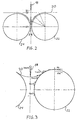
- Fig. 2 shows the movement of the folding blade in a Falzwalzenspalt 26 between two folding rollers 22, 24 for introducing a sheet 20 in the Falzwalzenspalt 26.
- S 1 the uppermost end position of the folding blade 18, with S 2, the height of the folding blade 18 when hitting the sheet 20 and s 3, the lowest position of the folding blade 18 marked.
- Fig. 3 shows the theoretical determination of the speed v sch of the folding blade 18 on the condition that the velocity v p of the sheet 20 and the tangential peripheral speed v fw of the folding rollers 22, 24 is equal.
- the velocity v sch is determined from a vector triangle. In this case, the vertically directed vector V sch is added to the top of the horizontal vector of the velocity v p .
- the length of the vertical vector V sch up to its point of intersection with the tangent to the folding roller through the beginning of the vector v p gives the magnitude of the velocity v sch .
- FIG. 4 An optimal time - distance diagram for the movement of the folding blade is shown in FIG. 4.
- the folding blade is moved at a relatively high speed between the positions s 1 and s 2 , wherein the folding blade is decelerated before the position s 2 , where it strikes the sheet, so that it strikes the sheet at low speed.
- the folding sword is until the lowest end position so moves the speed of the lower end of the folding blade in the direction of movement the folding blade portion of the Falzwalzensons Irish at the level of the lower end of the folding sword corresponds.
- the sheet is fed to the folding rollers at absolute folding roller peripheral speed to hand over.
- the folding blade is moved back abruptly in its uppermost end position.
- the backward movement is advantageously carried out at very high speed, which is so large that due to the inertia of the bow no sheet retreat possible is.
- the sheet speed, the folding roller speed and the speed of the sword until the sheet is transferred ideally equal.
- friction between the sheet and the folding rollers is prevented.
- good results are also achieved when the peripheral speed of the Fold rolls exceeds the bow speed by less than 15%.
- the voice coil drive is particularly suitable for controlling the movement of the folding blade well suited.
- other highly dynamic controllable drives are possible, such as. pneumatic or hydraulic.
Landscapes
- Folding Of Thin Sheet-Like Materials, Special Discharging Devices, And Others (AREA)
Description
- Fig. 1
- einen Querschnit einer Falzschwertantriebsvorrichtung
- Fig. 2
- die Übergabe eines Bogens in einen Falzwalzenspalt
- Fig. 3
- schematisch die Bestimmung der Falzschwertgeschwindigkeit
- Fig. 4
- ein Weg - Zeit - Diagramm der Falzschwertbewegung
- Fig. 5
- ein Weg - Zeit - Diagramm der Falzwertbewegung einer bekannten Falzschwertantriebsvorrichtung.
Claims (7)
- Falzschwertantriebsvorrichtung für eine Falzmaschine, mit einem Falzschwert (18), das an einem Ende einer von einem linearen Hubantrieb für eine Auf- und Abbewegung angetriebenen Antriebsstange (11) angebracht ist, um einen Bogen (20) in einen Falzwalzenspalt (26) zwischen zwei Falzwalzen (22, 24) zu führen, dadurch gekennzeichnet, dass der lineare Hubantrieb (28) durch eine Steuereinrichtung so gesteuert wird, dass das Falzschwert (18) den Bogen (20) mit niedriger Geschwindigkeit berührt und anschließend im wesentlichen mit dem in Bewegungsrichtung des Falzschwertes (18) verlaufenden Anteil (Vsch) der Umfangsgeschwindigkeit (Vfw) der Falzwalzen (22, 24) auf Höhe des unteren Endes des Falzschwertes (18) bis zum Einzug zwischen den Falzwalzen (22, 24) bewegt wird.
- Falzschwertantriebsvorrichtung nach Anspruch 1, dadurch gekennzeichnet, dass der lineare Hubantrieb (28) durch die Steuereinrichung so gesteuert wird, dass das im wesentlichen keine Reibung zwischen Bogen (20) und Falzwalzen (22, 24) vorhanden ist.
- Falzschwertantriebsvorrichtung nach Anspruch 1, dadurch gekennzeichnet, dass der lineare Hubantrieb (28) durch die Steuereinrichung so gesteuert wird, dass das Falzschwert (18) ruckartig zurückgezogen wird, nachdem die Falzwalzen (22, 24) beginnen den Bogen (20) selbstständig einzuziehen.
- Falzschwertantriebsvorrichtung nach einem der Ansprüche 1 bis 3, dadurch gekennzeichnet, dass der lineare Hubantrieb von einem Voice-Coil-Antrieb (28) gebildet wird, der einen Spulenkörper (9) und einen Magnetkörper (13) umfasst.
- Falzschwertantriebsvorrichtung nach Anspruch 4, dadurch gekennzeichnet, dass die Antriebsstange (11) in Längsrichtung verschiebbar gelagert durch ein Gehäuse (30) hindurchgeht, wobei der Spulenkörper (9) die Antriebsstange (11) umgebend in dem Gehäuse (30) befestigt ist, und der Magnetkörper (13) bezüglich des Spulenkörpers (9) dem Falzschwert (18) zugewandt und die Antriebsstange (11) umgebend an dieser befestigt ist.
- Falzschwertantriebsvorrichtung nach Anspruch 5, dadurch gekennzeichnet, dass der Magnetkörper (13) durch eine elastische Einrichtung (15) in Richtung des Spulenkörpers (9) vorgespannt ist, um ein Herunterfallen des Falzschwertes in stromlosen Zustand zu verhindern.
- Falzschwertantriebsvorrichtung nach Anspruch 5, dadurch gekennzeichnet, dass in Längsrichtung vor und hinter dem Magnetkörper (13) Endlagendämpfungseinrichtungen (10,15) im Gehäuse (30) angeordnet sind.
Priority Applications (2)
| Application Number | Priority Date | Filing Date | Title |
|---|---|---|---|
| EP20020005988 EP1354835B1 (de) | 2002-03-15 | 2002-03-15 | Falzschwertantriebsvorrichtung |
| DE50203335T DE50203335D1 (de) | 2002-03-15 | 2002-03-15 | Falzschwertantriebsvorrichtung |
Applications Claiming Priority (1)
| Application Number | Priority Date | Filing Date | Title |
|---|---|---|---|
| EP20020005988 EP1354835B1 (de) | 2002-03-15 | 2002-03-15 | Falzschwertantriebsvorrichtung |
Publications (2)
| Publication Number | Publication Date |
|---|---|
| EP1354835A1 EP1354835A1 (de) | 2003-10-22 |
| EP1354835B1 true EP1354835B1 (de) | 2005-06-08 |
Family
ID=28459445
Family Applications (1)
| Application Number | Title | Priority Date | Filing Date |
|---|---|---|---|
| EP20020005988 Expired - Lifetime EP1354835B1 (de) | 2002-03-15 | 2002-03-15 | Falzschwertantriebsvorrichtung |
Country Status (2)
| Country | Link |
|---|---|
| EP (1) | EP1354835B1 (de) |
| DE (1) | DE50203335D1 (de) |
Families Citing this family (1)
| Publication number | Priority date | Publication date | Assignee | Title |
|---|---|---|---|---|
| DE102005046688A1 (de) * | 2005-09-29 | 2007-04-05 | Heidelberger Druckmaschinen Ag | Schwertfalzwerk und Verfahren zum Einstellen eines Schwertfalzwerks |
Family Cites Families (2)
| Publication number | Priority date | Publication date | Assignee | Title |
|---|---|---|---|---|
| DE19843872B4 (de) * | 1998-09-25 | 2007-11-29 | Maschinenbau Oppenweiler Binder Gmbh & Co. Kg | Verfahren zur Steuerung und Regelung eines Falzmesserantriebs |
| DE20006369U1 (de) * | 2000-04-06 | 2000-08-10 | Maschinenbau Oppenweiler Binder GmbH & Co., 71570 Oppenweiler | Falzschwertantrieb |
-
2002
- 2002-03-15 EP EP20020005988 patent/EP1354835B1/de not_active Expired - Lifetime
- 2002-03-15 DE DE50203335T patent/DE50203335D1/de not_active Expired - Fee Related
Also Published As
| Publication number | Publication date |
|---|---|
| DE50203335D1 (de) | 2005-07-14 |
| EP1354835A1 (de) | 2003-10-22 |
Similar Documents
| Publication | Publication Date | Title |
|---|---|---|
| DE2346449C3 (de) | Einrichtung zur Steuerung der Vertikalbewegung eines Schreibstiftes in einem automatischen Zeichengerät oder dergleichen | |
| DE2535136C2 (de) | Halteeinrichtung in einer Druckvorrichtung zum Halten eines Einzelblattes oder eines einen Buchrücken aufweisenden Aufzeichnungsmediums | |
| DE19834078A1 (de) | Servo-Druckregler mit gestuftem Magnetanker | |
| DE2630931B2 (de) | Antriebseinrichtung für einen Nadeldrucker | |
| DE1061628B (de) | Steuereinrichtung fuer kombinierte Hand- und automatische Flugzeugsteueranlagen | |
| DE4414308C2 (de) | Kondensationsvorrichtung | |
| DE1959591A1 (de) | Bimetall-Temperaturregler | |
| EP2855311B1 (de) | Drucker mit einer vereinzelungsvorrichtung | |
| EP3115826A1 (de) | Vorrichtung zur ablenkung eines laserstrahls | |
| DE4322255A1 (de) | Dämpfungsvorrichtung | |
| EP0043898B1 (de) | Stellvorrichtung für die Andrückrollen von Bandhaspeln | |
| DE19727344C2 (de) | Linearstellglied | |
| EP1354835A1 (de) | Falzschwertantriebsvorrichtung | |
| DE2821842C2 (de) | Elektromagnetische Antriebsvorrichtung | |
| DE2532165C3 (de) | Spulvorrichtung | |
| DE734617C (de) | Einrichtung zum Spannen faden- oder bandfoermigen Gutes, insbesondere von Walzgut zwischen zwei Walzgeruesten | |
| DE1169275B (de) | Bahnlaufregler | |
| DE202017103367U1 (de) | Vorrichtung zum Stoppen eines Fördergutes auf einem Förderer | |
| EP3254997B1 (de) | Vorrichtung zum stoppen eines fördergutes auf einem förderer | |
| DE1526522A1 (de) | Geschwindigkeitsregler | |
| DE19818336C1 (de) | Elektrisch-pneumatischer Umformer sowie diesen umfassender Regler | |
| CH660720A5 (de) | Fadenbremsvorrichtung. | |
| AT18444U1 (de) | Führungssystem für Schiebetürflügel | |
| EP0362585B1 (de) | Rolltor | |
| DE2618742C3 (de) | Vorrichtung zum Auf- oder Abwickeln von streifenförmigen Aufzeichnungsträgern auf oder von Wickelspulen |
Legal Events
| Date | Code | Title | Description |
|---|---|---|---|
| PUAI | Public reference made under article 153(3) epc to a published international application that has entered the european phase |
Free format text: ORIGINAL CODE: 0009012 |
|
| 17P | Request for examination filed |
Effective date: 20030611 |
|
| AK | Designated contracting states |
Kind code of ref document: A1 Designated state(s): AT BE CH CY DE DK ES FI FR GB GR IE IT LI LU MC NL PT SE TR |
|
| AX | Request for extension of the european patent |
Extension state: AL LT LV MK RO SI |
|
| RAP1 | Party data changed (applicant data changed or rights of an application transferred) |
Owner name: MASCHINENBAU OPPENWEILERBINDER GMBH & CO. KG |
|
| AKX | Designation fees paid |
Designated state(s): DE FR GB IT |
|
| GRAP | Despatch of communication of intention to grant a patent |
Free format text: ORIGINAL CODE: EPIDOSNIGR1 |
|
| GRAS | Grant fee paid |
Free format text: ORIGINAL CODE: EPIDOSNIGR3 |
|
| GRAA | (expected) grant |
Free format text: ORIGINAL CODE: 0009210 |
|
| AK | Designated contracting states |
Kind code of ref document: B1 Designated state(s): DE FR GB IT |
|
| REG | Reference to a national code |
Ref country code: GB Ref legal event code: FG4D Free format text: NOT ENGLISH |
|
| REF | Corresponds to: |
Ref document number: 50203335 Country of ref document: DE Date of ref document: 20050714 Kind code of ref document: P |
|
| GBT | Gb: translation of ep patent filed (gb section 77(6)(a)/1977) |
Effective date: 20050916 |
|
| ET | Fr: translation filed | ||
| PLBE | No opposition filed within time limit |
Free format text: ORIGINAL CODE: 0009261 |
|
| STAA | Information on the status of an ep patent application or granted ep patent |
Free format text: STATUS: NO OPPOSITION FILED WITHIN TIME LIMIT |
|
| 26N | No opposition filed |
Effective date: 20060309 |
|
| PGFP | Annual fee paid to national office [announced via postgrant information from national office to epo] |
Ref country code: GB Payment date: 20090324 Year of fee payment: 8 |
|
| PGFP | Annual fee paid to national office [announced via postgrant information from national office to epo] |
Ref country code: DE Payment date: 20090406 Year of fee payment: 8 Ref country code: IT Payment date: 20090318 Year of fee payment: 8 |
|
| PGFP | Annual fee paid to national office [announced via postgrant information from national office to epo] |
Ref country code: FR Payment date: 20090325 Year of fee payment: 8 |
|
| GBPC | Gb: european patent ceased through non-payment of renewal fee |
Effective date: 20100315 |
|
| REG | Reference to a national code |
Ref country code: FR Ref legal event code: ST Effective date: 20101130 |
|
| PG25 | Lapsed in a contracting state [announced via postgrant information from national office to epo] |
Ref country code: FR Free format text: LAPSE BECAUSE OF NON-PAYMENT OF DUE FEES Effective date: 20100331 |
|
| PG25 | Lapsed in a contracting state [announced via postgrant information from national office to epo] |
Ref country code: DE Free format text: LAPSE BECAUSE OF NON-PAYMENT OF DUE FEES Effective date: 20101001 |
|
| PG25 | Lapsed in a contracting state [announced via postgrant information from national office to epo] |
Ref country code: IT Free format text: LAPSE BECAUSE OF NON-PAYMENT OF DUE FEES Effective date: 20100315 Ref country code: GB Free format text: LAPSE BECAUSE OF NON-PAYMENT OF DUE FEES Effective date: 20100315 |