EP1355014A2 - Unterdecke mit multifunktionalen modularen Elementen - Google Patents
Unterdecke mit multifunktionalen modularen Elementen Download PDFInfo
- Publication number
- EP1355014A2 EP1355014A2 EP03076058A EP03076058A EP1355014A2 EP 1355014 A2 EP1355014 A2 EP 1355014A2 EP 03076058 A EP03076058 A EP 03076058A EP 03076058 A EP03076058 A EP 03076058A EP 1355014 A2 EP1355014 A2 EP 1355014A2
- Authority
- EP
- European Patent Office
- Prior art keywords
- panels
- false ceiling
- connecting elements
- ceiling according
- arms
- Prior art date
- Legal status (The legal status is an assumption and is not a legal conclusion. Google has not performed a legal analysis and makes no representation as to the accuracy of the status listed.)
- Withdrawn
Links
Images

Classifications
-
- E—FIXED CONSTRUCTIONS
- E04—BUILDING
- E04B—GENERAL BUILDING CONSTRUCTIONS; WALLS, e.g. PARTITIONS; ROOFS; FLOORS; CEILINGS; INSULATION OR OTHER PROTECTION OF BUILDINGS
- E04B9/00—Ceilings; Construction of ceilings, e.g. false ceilings; Ceiling construction with regard to insulation
- E04B9/18—Means for suspending the supporting construction
- E04B9/20—Means for suspending the supporting construction adjustable
-
- E—FIXED CONSTRUCTIONS
- E04—BUILDING
- E04B—GENERAL BUILDING CONSTRUCTIONS; WALLS, e.g. PARTITIONS; ROOFS; FLOORS; CEILINGS; INSULATION OR OTHER PROTECTION OF BUILDINGS
- E04B9/00—Ceilings; Construction of ceilings, e.g. false ceilings; Ceiling construction with regard to insulation
- E04B9/22—Connection of slabs, panels, sheets or the like to the supporting construction
-
- E—FIXED CONSTRUCTIONS
- E04—BUILDING
- E04B—GENERAL BUILDING CONSTRUCTIONS; WALLS, e.g. PARTITIONS; ROOFS; FLOORS; CEILINGS; INSULATION OR OTHER PROTECTION OF BUILDINGS
- E04B9/00—Ceilings; Construction of ceilings, e.g. false ceilings; Ceiling construction with regard to insulation
- E04B9/32—Translucent ceilings, i.e. permitting both the transmission and diffusion of light
-
- E—FIXED CONSTRUCTIONS
- E04—BUILDING
- E04B—GENERAL BUILDING CONSTRUCTIONS; WALLS, e.g. PARTITIONS; ROOFS; FLOORS; CEILINGS; INSULATION OR OTHER PROTECTION OF BUILDINGS
- E04B9/00—Ceilings; Construction of ceilings, e.g. false ceilings; Ceiling construction with regard to insulation
- E04B9/34—Grid-like or open-work ceilings, e.g. lattice type box-like modules, acoustic baffles
Definitions
- the present invention relates to a false ceiling with multifunctional modular elements.
- False ceilings are light horizontal structures, generally hanging from an overlying loft, or vault, destined for creating a new ceiling for environments covered by said loft or vault.
- False ceilings are conceived with the function of creating a flat regular surface, where structural building elements, such as for example loft beams, disturb the aesthetic appearance of the environment.
- the material of which false ceilings are made can exert specific functions such as acoustic absorption and thermal insulation.
- False ceilings consist of a series of panels arranged side-by-side forming a flat continuous surface.
- the panels generally hang from the loft by means of wires or are fixed to a supporting structure situated under the loft.
- Lighting and other environmental accessories such as air-conditioning inlets, fire-sprinklers, smoke detectors and other sensors, are arranged and fixed below the false ceiling, creating connection openings with the respective electric cables or feed pipes, situated above the false ceiling.
- the lighting and other accessories can be inserted in openings situated in the false ceiling.
- the arranging of a false ceiling consequently involves the insertion of openings in the panels both when the lighting and other accessories are fixed below the false ceiling and also when they are inserted inside the false ceiling.
- openings are preferably produced on the panels before they are hung or constrained to the supporting structure, and consequently in a preparation phase which precedes the placing of the false ceiling.
- the stripped opening must be covered and it is not easy to obtain aesthetically acceptable results, unless the whole panel or panels in question are replaced.
- An objective of the present invention is to avoid the drawbacks mentioned above and in particular to produce a false ceiling which allows the rapid installation of light sources and other multifunctional accessories with which the false ceiling is provided.
- Another objective of the present invention is to produce a false ceiling which allows a considerable flexibility, so as to be able to easily vary the arrangement of light sources or other accessories, as well as to facilitate the addition or removal of said elements.
- a further objective of the present invention is to produce a false ceiling which is particularly reliable, simple, functional and at relatively low costs.
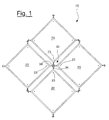
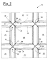
- a false ceiling is illustrated, indicated as a whole with 10, hanging from a loft 12, and comprising modular elements, such as panels 20 and connecting elements 30.
- the panels 20 are square.
- a second panel 20 can be positioned above the frame 22.
- the panels 20 are attached to the frame 22 with fixing elements, such as screws 23.
- the frame 22 can also be covered on the external side by four corners 24, for example with a "C"-shaped section.
- the panels 20 are sustained by the connecting elements 30.
- the connecting elements 30 have a central body 32, for example cylindrical, from which from one to four hooked arms 34 extend outwards, depending on the specific necessity and composition to be obtained.
- These arms 34 extend in directions offset from each other by 90°.
- Each of the arms 34 has a free end 36, which is attached near a vertex of the panel 20, for example by means of any fixing or hooking device, such as a screw 38 screwed in correspondence with a hole 28 situated above the frame 22, close to each of the four vertexes of the square.
- an accessory 37 such as a light source.
- the dowels 42 are first arranged on the ceiling 12, in such positions as to create a square-meshed network on the ceiling 12, having one side equal to the sum of the side of the frame 22 and double the distance of the free end 36 of the arm 34 from the axis of the connecting element 30.
- connecting elements 30 are hung from the dowels 42, they can be fixed to each connecting element 30 up to four frames 22, previously equipped with panels 20.
- the arms 34 of the connecting elements 30 can be connected to the frames 22, this structure being assembled on the ground. It is then hoisted up to the ceiling, hanging the connecting elements 30 to the dowels 42. The panels 20 are then assembled.
- the connecting element 30 can be used to receive, again beneath its central body 32, other accessories 37, such as a smoke detector, a presence sensor, a light sensor, a fire-sprinkler, a colour temperature sensor, a temperature sensor, a humidity sensor, etc.
- other accessories 37 such as a smoke detector, a presence sensor, a light sensor, a fire-sprinkler, a colour temperature sensor, a temperature sensor, a humidity sensor, etc.
- the panels 20 made for example of a sound-proof material, as already mentioned, are fixed, or inserted in a perimetric frame 22.
- two panels 20 made of a transparent or diffusing material are fixed below and above the frame 22.
- a fluorescent tube or halogenous source or LED diodes or another light source is situated above the two panels 20, or on a part of the frame 22 facing the panels 20.
- a direct and indirect light diffusing apparatus is formed, i.e. the light emission can be directed solely upwards or solely downwards or a combination thereof.
- light sources are inserted between the two panels 20, made of a diffusing material, with the relative components and optics, thus creating a direct and indirect diffusing light apparatus, i.e. the emission can be directed solely upwards or solely downwards or a combination thereof.
- the panel 20 can be partially used as a diffuser and partially as a false ceiling, thus creating a luminous strip or circle or square, or yet other figures.
- the light source with the relative reflector and components can be arranged in the frame 22 or between the diffusing panels 20.
- the present invention does not only relate to square-shaped panels 20 such as those illustrated in the figures.
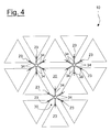
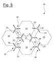
- the panels 20 can in fact have any regular geometric polygonal shape, for example, an equilateral triangle or regular hexagon, as shown in figures 4 and 5 respectively.
- Said panels 20 are arranged with facing sides parallel to each other.
- the connecting elements 30 must have not more than from one to four arms 34, but from one to six for an equilateral triangle and from one to three for a regular hexagon, respectively.
- Said arms 34 are arranged on a round angle so that between the arms there are 34 angles equal to or multiples of 360°/n, wherein n indicates the maximum number of regular polygons, having the same panel 20 shape, which can surround, flanking their respective sides, the panel 20 itself.
- angles equal to or multiples of 60° there are angles equal to or multiples of 120°.
Landscapes
- Engineering & Computer Science (AREA)
- Architecture (AREA)
- Physics & Mathematics (AREA)
- Electromagnetism (AREA)
- Civil Engineering (AREA)
- Structural Engineering (AREA)
- Non-Portable Lighting Devices Or Systems Thereof (AREA)
- Residential Or Office Buildings (AREA)
Applications Claiming Priority (2)
| Application Number | Priority Date | Filing Date | Title |
|---|---|---|---|
| ITMI20020815 | 2002-04-17 | ||
| IT2002MI000815A ITMI20020815A1 (it) | 2002-04-17 | 2002-04-17 | Controsoffitto con elementi modulari multifunzionali |
Publications (2)
| Publication Number | Publication Date |
|---|---|
| EP1355014A2 true EP1355014A2 (de) | 2003-10-22 |
| EP1355014A3 EP1355014A3 (de) | 2004-12-22 |
Family
ID=11449722
Family Applications (1)
| Application Number | Title | Priority Date | Filing Date |
|---|---|---|---|
| EP03076058A Withdrawn EP1355014A3 (de) | 2002-04-17 | 2003-04-11 | Unterdecke mit multifunktionalen modularen Elementen |
Country Status (4)
| Country | Link |
|---|---|
| EP (1) | EP1355014A3 (de) |
| CN (1) | CN1453440A (de) |
| IT (1) | ITMI20020815A1 (de) |
| NO (1) | NO20031628L (de) |
Cited By (4)
| Publication number | Priority date | Publication date | Assignee | Title |
|---|---|---|---|---|
| CN101806114A (zh) * | 2010-03-19 | 2010-08-18 | 陈晓锋 | 一种条扣导光天花 |
| WO2016011901A1 (zh) * | 2014-07-25 | 2016-01-28 | 杨东佐 | 一种吊顶天花 |
| JP2016142351A (ja) * | 2015-02-03 | 2016-08-08 | 有限会社アールストーン | 吊りボルトの振動抑制体 |
| DE102015211633A1 (de) * | 2015-06-23 | 2016-12-29 | Lichtraeume Gercek und Muralter GbR (vertretungsberechtigte Gesellschafter: Fatih Gercek, 10179 Berlin; Susana Ferreras-Diaz, 10779 Berlin) | Beleuchtungseinheit und Beleuchtungssystem |
Families Citing this family (1)
| Publication number | Priority date | Publication date | Assignee | Title |
|---|---|---|---|---|
| CN106760372A (zh) * | 2017-03-15 | 2017-05-31 | 镇江力点锚固有限公司 | 一种石材干挂配件 |
Family Cites Families (2)
| Publication number | Priority date | Publication date | Assignee | Title |
|---|---|---|---|---|
| CH445794A (fr) * | 1965-10-07 | 1967-10-31 | Lambert Paul | Faux plafond |
| DE3943510A1 (de) * | 1989-09-30 | 1991-04-11 | Huelsta Werke Huels Kg | Tragkonstruktion fuer eine abgehaengte decke |
-
2002
- 2002-04-17 IT IT2002MI000815A patent/ITMI20020815A1/it unknown
-
2003
- 2003-04-09 NO NO20031628A patent/NO20031628L/no not_active Application Discontinuation
- 2003-04-11 EP EP03076058A patent/EP1355014A3/de not_active Withdrawn
- 2003-04-17 CN CN03123114.4A patent/CN1453440A/zh active Pending
Cited By (4)
| Publication number | Priority date | Publication date | Assignee | Title |
|---|---|---|---|---|
| CN101806114A (zh) * | 2010-03-19 | 2010-08-18 | 陈晓锋 | 一种条扣导光天花 |
| WO2016011901A1 (zh) * | 2014-07-25 | 2016-01-28 | 杨东佐 | 一种吊顶天花 |
| JP2016142351A (ja) * | 2015-02-03 | 2016-08-08 | 有限会社アールストーン | 吊りボルトの振動抑制体 |
| DE102015211633A1 (de) * | 2015-06-23 | 2016-12-29 | Lichtraeume Gercek und Muralter GbR (vertretungsberechtigte Gesellschafter: Fatih Gercek, 10179 Berlin; Susana Ferreras-Diaz, 10779 Berlin) | Beleuchtungseinheit und Beleuchtungssystem |
Also Published As
| Publication number | Publication date |
|---|---|
| EP1355014A3 (de) | 2004-12-22 |
| CN1453440A (zh) | 2003-11-05 |
| NO20031628L (no) | 2003-10-20 |
| ITMI20020815A1 (it) | 2003-10-17 |
| ITMI20020815A0 (it) | 2002-04-17 |
| NO20031628D0 (no) | 2003-04-09 |
Similar Documents
| Publication | Publication Date | Title |
|---|---|---|
| US20220010554A1 (en) | Linear Profile Support Element and Lighting Module For Suspended Ceiling Systems | |
| US7338182B1 (en) | Lighting fixture housing for suspended ceilings and method of installing same | |
| US11280457B2 (en) | Diffuse lighting systems | |
| US20150204489A1 (en) | Electronic moulding trim | |
| US12312805B2 (en) | Multifunctional lighting assembly for a T-bar grid arrangement | |
| US7824059B1 (en) | Low-glare integrally-recessed ceiling light fixtures | |
| US12454825B2 (en) | Diffuse lighting systems | |
| US20120186175A1 (en) | Suspended ceiling grid system | |
| US20210348730A1 (en) | Suspended ceiling light with integrated cross-tees | |
| CN219100464U (zh) | 泛灯光格栅吊顶结构 | |
| US8342722B1 (en) | Light system | |
| CN207812793U (zh) | 一种吊顶结构 | |
| US7856788B2 (en) | Recessed wall-wash staggered mounting method | |
| US7845821B2 (en) | Flourescent lighting fixture module for indirect lighting of interior spaces, and method | |
| JP2003082797A (ja) | 組立式ブースシステム | |
| JPH0877810A (ja) | 間接照明構造 | |
| US20250314377A1 (en) | Accent shelf light for wall or ceiling | |
| CN1453440A (zh) | 具有多功能组合式构件的假天花板 | |
| KR200424325Y1 (ko) | 천장 매립등 | |
| CN210658908U (zh) | 一种造型吊顶安装结构 | |
| JP7702650B2 (ja) | 支持装置及びシステム天井 | |
| CN121002325A (zh) | 用于天花板悬置天窗灯具的安装布置 | |
| KR200320806Y1 (ko) | 천정 조명기구용 지지구 | |
| JP2628813B2 (ja) | ユニットルームの天井構造 | |
| JPS6337685Y2 (de) |
Legal Events
| Date | Code | Title | Description |
|---|---|---|---|
| PUAI | Public reference made under article 153(3) epc to a published international application that has entered the european phase |
Free format text: ORIGINAL CODE: 0009012 |
|
| AK | Designated contracting states |
Kind code of ref document: A2 Designated state(s): AT BE BG CH CY CZ DE DK EE ES FI FR GB GR HU IE IT LI LU MC NL PT RO SE SI SK TR |
|
| AX | Request for extension of the european patent |
Extension state: AL LT LV MK |
|
| PUAL | Search report despatched |
Free format text: ORIGINAL CODE: 0009013 |
|
| AK | Designated contracting states |
Kind code of ref document: A3 Designated state(s): AT BE BG CH CY CZ DE DK EE ES FI FR GB GR HU IE IT LI LU MC NL PT RO SE SI SK TR |
|
| AX | Request for extension of the european patent |
Extension state: AL LT LV MK |
|
| AKX | Designation fees paid | ||
| REG | Reference to a national code |
Ref country code: DE Ref legal event code: 8566 |
|
| STAA | Information on the status of an ep patent application or granted ep patent |
Free format text: STATUS: THE APPLICATION IS DEEMED TO BE WITHDRAWN |
|
| 18D | Application deemed to be withdrawn |
Effective date: 20050623 |