EP1355337A2 - Interrupteur à vide - Google Patents
Interrupteur à vide Download PDFInfo
- Publication number
- EP1355337A2 EP1355337A2 EP03003761A EP03003761A EP1355337A2 EP 1355337 A2 EP1355337 A2 EP 1355337A2 EP 03003761 A EP03003761 A EP 03003761A EP 03003761 A EP03003761 A EP 03003761A EP 1355337 A2 EP1355337 A2 EP 1355337A2
- Authority
- EP
- European Patent Office
- Prior art keywords
- vacuum
- vacuum container
- switch
- grounding
- conductor
- Prior art date
- Legal status (The legal status is an assumption and is not a legal conclusion. Google has not performed a legal analysis and makes no representation as to the accuracy of the status listed.)
- Granted
Links
Images

Classifications
-
- H—ELECTRICITY
- H01—ELECTRIC ELEMENTS
- H01H—ELECTRIC SWITCHES; RELAYS; SELECTORS; EMERGENCY PROTECTIVE DEVICES
- H01H33/00—High-tension or heavy-current switches with arc-extinguishing or arc-preventing means
- H01H33/60—Switches wherein the means for extinguishing or preventing the arc do not include separate means for obtaining or increasing flow of arc-extinguishing fluid
- H01H33/66—Vacuum switches
-
- H—ELECTRICITY
- H01—ELECTRIC ELEMENTS
- H01H—ELECTRIC SWITCHES; RELAYS; SELECTORS; EMERGENCY PROTECTIVE DEVICES
- H01H33/00—High-tension or heavy-current switches with arc-extinguishing or arc-preventing means
- H01H33/60—Switches wherein the means for extinguishing or preventing the arc do not include separate means for obtaining or increasing flow of arc-extinguishing fluid
- H01H33/66—Vacuum switches
- H01H33/666—Operating arrangements
- H01H33/6661—Combination with other type of switch, e.g. for load break switches
-
- H—ELECTRICITY
- H01—ELECTRIC ELEMENTS
- H01H—ELECTRIC SWITCHES; RELAYS; SELECTORS; EMERGENCY PROTECTIVE DEVICES
- H01H1/00—Contacts
- H01H1/58—Electric connections to or between contacts; Terminals
- H01H1/5822—Flexible connections between movable contact and terminal
-
- H—ELECTRICITY
- H01—ELECTRIC ELEMENTS
- H01H—ELECTRIC SWITCHES; RELAYS; SELECTORS; EMERGENCY PROTECTIVE DEVICES
- H01H1/00—Contacts
- H01H1/58—Electric connections to or between contacts; Terminals
- H01H1/5822—Flexible connections between movable contact and terminal
- H01H2001/5827—Laminated connections, i.e. the flexible conductor is composed of a plurality of thin flexible conducting layers
-
- H—ELECTRICITY
- H01—ELECTRIC ELEMENTS
- H01H—ELECTRIC SWITCHES; RELAYS; SELECTORS; EMERGENCY PROTECTIVE DEVICES
- H01H33/00—High-tension or heavy-current switches with arc-extinguishing or arc-preventing means
- H01H33/60—Switches wherein the means for extinguishing or preventing the arc do not include separate means for obtaining or increasing flow of arc-extinguishing fluid
- H01H33/66—Vacuum switches
- H01H33/666—Operating arrangements
- H01H2033/6668—Operating arrangements with a plurality of interruptible circuit paths in single vacuum chamber
-
- H—ELECTRICITY
- H01—ELECTRIC ELEMENTS
- H01H—ELECTRIC SWITCHES; RELAYS; SELECTORS; EMERGENCY PROTECTIVE DEVICES
- H01H31/00—Air-break switches for high tension without arc-extinguishing or arc-preventing means
- H01H31/003—Earthing switches
-
- H—ELECTRICITY
- H01—ELECTRIC ELEMENTS
- H01H—ELECTRIC SWITCHES; RELAYS; SELECTORS; EMERGENCY PROTECTIVE DEVICES
- H01H33/00—High-tension or heavy-current switches with arc-extinguishing or arc-preventing means
- H01H33/60—Switches wherein the means for extinguishing or preventing the arc do not include separate means for obtaining or increasing flow of arc-extinguishing fluid
- H01H33/66—Vacuum switches
- H01H33/668—Means for obtaining or monitoring the vacuum
Definitions
- the present invention relates to a noble vacuum switch containing therein a plurality of grounding switches in a switchgear.
- Vacuum switches each of which is provided with a plurality of grounding switches in a vacuum container are disclosed, for example, in JP A 2000-268685 and JP A 2000-268686. Those vacuum switches each accommodate the plurality of grounding switches in the vacuum container, however, each grounding switch is made a pair with other switch and independently arranged, and respective grounding switches are not connected inside the vacuum container.
- An object of the present invention is to provide a compact vacuum switch which reduces an external space of the vacuum switch.
- the present invention makes it possible to reduce an exterior space of a vacuum container and provide a compact vacuum switch by connecting, inside the vacuum container, respective switches in the vacuum container and providing a single grounding terminal connecting to an external of the vacuum container in a switchgear, particularly, in the vacuum switch containing therein a plurality of grounding switches.
- the present invention resided in a vacuum switch which comprises fixed electrodes of a plurality of circuit breaker portions or disconnector portions as load switches, movable electrodes which contact with separate from the fixed electrodes, fixed electrodes of a plurality of grounding device portions, movable electrodes which contact with and separate from the fixed electrodes thereof, each contained in a vacuum container, insulating bushings led out from the vacuum container, load conductors led out from the insulating bushings, a vacuum degree measuring device grounded on the vacuum container, and operation rods driving the movable blades of the circuit breaker portions or disconnector portions and the grounding device portions.
- the present invention resides in a vacuum container which comprises a plurality of circuit breaker portions or/and disconnector portions, and grounding switches, and in which, particularly, a plurality of the grounding switches are electrically connected to each other in the vacuum container.
- the present invention resides in a vacuum switch which comprises a vacuum container, a grounding switch and a load switch each disposed in the vacuum container, and an external connection conductor disposed in the vacuum container and to be connected electrically inside and outside the vacuum container, and which is characterized in that the grounding switch and the external connection conductor are electrically connected to each other inside the vacuum container.
- the present invention resides in a vacuum switch comprising a vacuum container, a plurality of grounding switches and a load switch each disposed in the vacuum container, and an external connection conductor disposed in the vacuum container and connected electrically inside and outside the vacuum container, and characterized in that the plurality of grounding switches are electrically connected to each other in the vacuum container and the grounding switches and the external connection conductor are electrically connected to each other in the vacuum container.
- the present invention resides in a vacuum switch comprising a vacuum container, a grounding switch and a load switch each disposed in the vacuum container, and an external connection conductor disposed in the vacuum container and to be connected electrically inside and outside the vacuum container, and characterized in that a movable side electrode of the grounding switch is electrically connected, inside the vacuum container, to a movable rod insulated from the vacuum container and to be connected to an external, and the grounding switch and the external connection conductor are electrically connected to each other in the vacuum container.
- the present invention resides in a vacuum switch comprising a vacuum container, a grounding switch and a load switch each disposed in the vacuum container, and an external connection conductor disposed in the vacuum container and to be connected electrically inside and outside the vacuum container, and characterized in that a fixed side electrode of the grounding switch and a fixed side electrode of at least one of the circuit breaker portion and disconnector portion are connected by a conductor inside the vacuum container to be an integrate, and the grounding switch and the external connection conductor are electrically connected to each other in the vacuum container.
- the vacuum circuit breaker portion is composed of necessary components for effecting vacuum circuit breaking, such as a movable electrode, fixed electrode, conductors supporting them and a vacuum container containing therein them.
- the disconnector portion is a device connected to the circuit breaker portion and holding the circuit breaker portion in a condition of being disconnected when necessary, and including a vacuum container accommodating therein components thereof.
- the respective grounding switches are connected by a flexible conductor, so that the respective grounding switches can be operated independently from each other to be at make and at break.
- the flexible conductor is arranged in the vacuum container, in order to be operated in the vacuum, the flexible conductor is constructed in such a structure that current passage portion is composed of laminated thin plates (0.1mm-0.2mm) of non-copper and stainless steel plates each inserted therebetween, being thinner than the non-copper plate and having an oxidized layer, whereby the non-copper plates are not adhered each other and the flexibility can be kept.
- the above-mentioned flexible conductor prefferably be a convex shape in an opposite direction to the current passage portion so that a sufficient distance between the flexible conductor and the main circuit current passage portion can be taken.
- such a structure is desirable that plating, preferably silver plating is provided at connection portions between the flexible conductor and respective grounding switches, the plating at the connection portions is melted at a vacuum brazing temperature when the vacuum container is being manufactured, and the flexible conductor and the respective grounding switches are joined.
- plating preferably silver plating is provided at connection portions between the flexible conductor and respective grounding switches, the plating at the connection portions is melted at a vacuum brazing temperature when the vacuum container is being manufactured, and the flexible conductor and the respective grounding switches are joined.
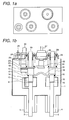
- Fig. 1a is an upper plane view of a vacuum switch of an embodiment of the present invention
- Fig. 1b is a sectional view of the vacuum switch of Fig. 1a.
- a grounded vacuum container 1 movable electrodes 12, 13 and fixed electrodes of two circuit breaker portions or disconnector portions, and a movable electrode 15 and a fixed electrode of one grounding device portion are contained, and a vacuum pressure measuring terminal 25 of a vacuum pressure measuring device mounted on the grounded vacuum container 1 is provided.
- the two circuit breaker portions or disconnector portions are arranged in a row
- the one grounding device portion and external connection portion 27 are arranged in a row and the row are in parallel with each other.
- An external connection conductor 27 is insulated from and connected to the grounded vacuum container 1 by upper and lower non-magnetic stainless steel caps sandwiching a cylindrical insulator made of ceramics such as alumina, zirconia, or the like and disposed at a central portion in the outside of the grounded vacuum container 1.
- the grounded vacuum container 1 is made of conductive material such as metal of high strength, non-magnetic stainless steel, etc., and the grounded vacuum container 1 is grounded.
- the vacuum pressure of the grounded vacuum container 1 is monitored by the vacuum measuring device 25.
- Insulation between the grounded vacuum container 1 and vacuum container internal conductors are kept by insulators 4, 5, 19, 20, 21, 26 made of the above-mentioned ceramics.
- the fixed electrode 10 and movable electrode 12, the fixed electrode 11 and movable electrode 13, and the fixed electrode 14 and movable electrode 15, which are contactable and separable from each other, are arranged inside the grounded vacuum container 1, and respective movable electrodes are made to contact with and separate from respective fixed electrodes by a command of an operation mechanism to make and brake.
- the movable electrodes 12, 13 and 15 are connected to movable conductors 16, 17 and 18, respectively, and the movable conductors 16, 17 and 18 are connected to movable rods 28, 29 and 30 through insulators 19, 20 and 21, respectively and connected to operation mechanism portions.
- the movable rods 28, 29 and 30 are air-tightly sealed by bellows 22, 23 and 24, respectively.
- Shield covers made of non-magnetic stainless steel are provided around a connection portion of the fixed electrode 10 and movable electrode 12 and a connection portion of the fixed electrode 11 and movable electrode 13.
- the fixed electrode 10 is connected to a connection conductor 2 and connected to an external of the grounded vacuum container 1 therethrough.
- the fixed electrode 11 is connected to a connection conductor 3 and connected to an external of the grounded vacuum container 1.
- the connection conductors 2, 3 are covered with insulators 4, 5, respectively, outside the grounded vacuum container 1.
- connection conductor 2 and connection conductor 3, each of which is connected to the external, are electrically connected when the movable electrodes 13 and 12 are in the condition of being in contact with the fixed electrodes since the movable conductor 16 and the movable conductor 17 are connected through a flexible conductor 31.
- the grounding portion fixed conductor 14 is connected to a grounding terminal portion conductor 33 through a flexible conductor 32, so that the grounding portion fixed conductor is electrically connected to the external connection conductor 27 when the grounding portion movable electrode 15 is in contact with the fixed electrode.
- the external connection conductor 27 is connected to the grounding terminal portion conductor 33 connected to the connection portion of the flexible conductor 32 thereby to be formed in an integrate, and the external connection conductor 27 is insulated from the grounded vacuum container 1 by the insulator 26.
- a current passage portion of each of the flexible conductors is formed of laminated thin plates (0.1mm - 0.2mm) of non-oxygen copper and stainless steel plates inserted between the thin plates, each stainless plate having an oxidized layer and being thinner than the non-oxygen copper thin plate, whereby the current passage portion is made in a structure in which non-oxygen copper plates are not adhered each other in vacuum and its flexibility can be kept.
- the flexible conductor is formed in a convex-shape to an opposite direction to the current passage portion so that a sufficient distance between the flexible conductor and a main circuit current passage portion can be taken.
- silver plating is provided for a connecting portion between the flexible conductor 32 and the movable conductor 18 of a grounding switch, the connecting portion is connected by melting a blazing material of silver at a vacuum brazing temperature when the vacuum container is manufactured.
- the vacuum switch containing therein the grounding switches of the present embodiment it is possible to reduce an exterior space of the vacuum container and make the vacuum switch compact by connecting, inside the vacuum container, the respective grounding switches disposed inside the vacuum container and by performing connection to the external of the vacuum container by a single grounding terminal.
- Fig. 2a is an upper plane view of a vacuum switch of another embodiment 2 of the present invention
- Fig. 2b is a sectional view of the vacuum switch of Fig. 2a.
- the present embodiment contains a pair of switch of the circuit breaker portion or disconnector portion and a grounding switch in addition to the embodiment 1 of Figs. 1a and 1b, and connects between respective circuits by the respective flexible conductors 31, 32. Therefore, a basic construction of the present embodiment is the same as the embodiment 1 and the manufacturing method also is similar thereto.
- grounding portion switches since movable conductors of a first circuit and a second circuit are connected to the grounding portions through a flexible conductor, when the grounding portion movable electrode of the first circuit is made at make and the grounding portion movable electrode of the second circuit is made at break, the first circuit is grounded through the grounding terminal portion, and it is possible to ground the second circuit by turning the grounding portion movable electrode of the first circuit at break and turning the grounding portion movable electrode of the second circuit at make. Further, it is possible to ground both the first and second circuits through the grounding terminal portion by turning the grounding portion movable electrode at make.
- the second circuit is grounded through the flexible conductor of the circuit breaker or disconnector portion, so that in the case of turning the grounding portion movable electrode of the second circuit to be at make, such an interlock that the movable electrode of the circuit breaker portion or disconnector portion of the first circuit is at break and can not be operated to be at make is provided.
- the second circuit also, in the similar manner, in the case where the grounding portion movable electrode of the second circuit is at make, such an interlock that the movable electrode of the circuit breaker portion or disconnector portion of the second circuit is at break and can not be operated to be at make is provided.
- the vacuum switch containing therein the grounding switches of the present embodiment it is possible to reduce an exterior space of the vacuum container and make the vacuum switch compact by connecting, inside the vacuum container, the respective grounding switches disposed inside the vacuum container and by performing connection to the external of the vacuum container by the single grounding terminal.
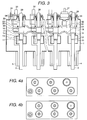
- Fig. 3 is a sectional view of a vacuum switch of a further another embodiment 3 of the present invention.
- the present embodiment contains a switch of a circuit breaker portion or disconnector portion and a grounding switch in addition to the embodiment 2 of Figs. 2a and 2b, and connects between respective circuits by the respective flexible conductors 31, 32. Therefore, a basic construction of the present embodiment is the same as the embodiment 1 and the manufacturing method also is similar thereto.
- any circuit can be grounded from a single grounding terminal by connecting respective circuits by the flexible conductor and turning the electrode of each circuit at make through the flexible conductor.
- the vacuum switch containing therein the grounding switches of the present embodiment it is possible to reduce an exterior space of the vacuum container and make the vacuum switch compact by connecting, inside the vacuum container, the respective grounding switches disposed in the vacuum container and by performing connection to the external of the vacuum container by the single grounding terminal.
- Figs. 4a and 4b each are an upper plane view of Fig. 3.
- an arrangement of respective switches of circuit breaker or disconnector portions and an arrangement of the grounding switch and the external connection conductor are in parallel with each other, but a zigzag arrangement as shown in Fig. 4a is preferable to secure a sufficient insulation distance.
- a lattice-like arrangement as shown in Fig. 4b.
- the vacuum switch accommodating therein the grounding switches of the present invention also, it is possible to reduce an outside space of the vacuum container and make a compact vacuum switch by connecting each grounding switch of the interior of the vacuum container inside the vacuum container and providing a single grounding terminal through which the external of the vacuum container is connected.
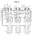
- Fig. 5 is a sectional view of a vacuum switch of still further another embodiment 4 of the present invention.
- the vacuum switch accommodating therein the grounding switches of the present invention also, it is possible to reduce the exterior space of the vacuum container and make a compact vacuum switch by connecting each grounding switch of the interior of the vacuum container inside the vacuum container and providing a single grounding terminal through which the external of the vacuum container is connected.
- the present invention it is possible to reduce a space necessary for the external or exterior of the vacuum container and provide a compact vacuum switchgear by connecting the grounding switch inside the vacuum container and constructing so as to perform the connection to the external of the vacuum container by a single grounding terminal.
Landscapes
- High-Tension Arc-Extinguishing Switches Without Spraying Means (AREA)
- Gas-Insulated Switchgears (AREA)
- Packages (AREA)
Applications Claiming Priority (2)
| Application Number | Priority Date | Filing Date | Title |
|---|---|---|---|
| JP2002113152A JP4135870B2 (ja) | 2002-04-16 | 2002-04-16 | 真空スイッチ |
| JP2002113152 | 2002-04-16 |
Publications (3)
| Publication Number | Publication Date |
|---|---|
| EP1355337A2 true EP1355337A2 (fr) | 2003-10-22 |
| EP1355337A3 EP1355337A3 (fr) | 2006-08-09 |
| EP1355337B1 EP1355337B1 (fr) | 2015-04-08 |
Family
ID=28672608
Family Applications (1)
| Application Number | Title | Priority Date | Filing Date |
|---|---|---|---|
| EP03003761.8A Expired - Lifetime EP1355337B1 (fr) | 2002-04-16 | 2003-02-19 | Interrupteur à vide |
Country Status (6)
| Country | Link |
|---|---|
| US (2) | US6855903B2 (fr) |
| EP (1) | EP1355337B1 (fr) |
| JP (1) | JP4135870B2 (fr) |
| KR (1) | KR100929220B1 (fr) |
| CN (1) | CN1215512C (fr) |
| TW (1) | TWI262519B (fr) |
Cited By (2)
| Publication number | Priority date | Publication date | Assignee | Title |
|---|---|---|---|---|
| EP1548779A3 (fr) * | 2003-12-26 | 2005-08-03 | Hitachi, Ltd. | Système de commutation à vide |
| CN103915282A (zh) * | 2014-04-25 | 2014-07-09 | 协励行(厦门)电气有限公司 | 新型固体绝缘真空开关三工位隔离接地开关模块 |
Families Citing this family (10)
| Publication number | Priority date | Publication date | Assignee | Title |
|---|---|---|---|---|
| JP4403782B2 (ja) * | 2003-11-17 | 2010-01-27 | 株式会社日立製作所 | 真空スイッチギヤ |
| JP4423598B2 (ja) * | 2004-08-17 | 2010-03-03 | 株式会社日立製作所 | 真空スイッチギヤの単相モジュールおよび真空スイッチギヤ |
| JP4162664B2 (ja) * | 2005-02-22 | 2008-10-08 | 株式会社日立製作所 | 真空スイッチギヤ |
| US7724489B2 (en) * | 2007-08-18 | 2010-05-25 | Ema Electromecanica S.A. | Circuit breaker with high speed mechanically-interlocked grounding switch |
| JP4982579B2 (ja) * | 2010-03-12 | 2012-07-25 | 株式会社日立製作所 | スイッチギヤ及びスイッチギヤの連動試験方法 |
| DE102013210136A1 (de) * | 2013-05-30 | 2014-12-04 | Siemens Aktiengesellschaft | Elektrisches Schaltgerät |
| CN103646800B (zh) * | 2013-12-05 | 2015-10-28 | 北京双杰电气股份有限公司 | 双投负荷开关 |
| WO2018110107A1 (fr) * | 2016-12-15 | 2018-06-21 | 三菱電機株式会社 | Conducteur flexible et disjoncteur à vide utilisant un conducteur flexible |
| US10784063B1 (en) | 2019-06-27 | 2020-09-22 | EMA Electromechanics, Inc. | Air insulated grounding switch |
| US10672573B1 (en) | 2019-06-27 | 2020-06-02 | EMA Electromechanis, Inc. | Gas insulated grounding switch |
Family Cites Families (11)
| Publication number | Priority date | Publication date | Assignee | Title |
|---|---|---|---|---|
| US3911567A (en) * | 1973-04-06 | 1975-10-14 | Fischer Ag Georg | Method of manufacturing an electric conductor of metal strips |
| US4445162A (en) * | 1981-09-02 | 1984-04-24 | Siemens-Allis, Inc. | Compact chassis plate for switchgear enclosure |
| US6144005A (en) * | 1997-07-23 | 2000-11-07 | Hitachi, Ltd. | Vacuum switch and a vacuum switchgear using the same |
| EP1615309B1 (fr) * | 1997-09-29 | 2008-04-09 | Mitsubishi Denki Kabushiki Kaisha | Appareil de commutation |
| EP1119011A4 (fr) * | 1998-10-02 | 2004-03-03 | Hitachi Ltd | Interrupteur sous vide et appareillage de commutation sous vide utilisant l'interrupteur sous vide |
| JP4297549B2 (ja) | 1999-03-17 | 2009-07-15 | 三菱電機株式会社 | スイッチギヤ |
| JP2000268686A (ja) | 1999-03-18 | 2000-09-29 | Mitsubishi Electric Corp | スイッチギヤ |
| JP3788148B2 (ja) | 1999-12-16 | 2006-06-21 | 株式会社日立製作所 | 真空スイッチ及びその運転方法 |
| JP2001307603A (ja) * | 2000-04-19 | 2001-11-02 | Hitachi Ltd | 真空スイッチ及びそれを用いた真空スイッチギヤ |
| JP2001351438A (ja) | 2000-06-02 | 2001-12-21 | Hitachi Ltd | フレキシブル導体、その製造方法及び真空スイッチ |
| US6753493B2 (en) * | 2001-06-01 | 2004-06-22 | Hubbell Incorporated | Electrical circuit interrupting device |
-
2002
- 2002-04-16 JP JP2002113152A patent/JP4135870B2/ja not_active Expired - Fee Related
-
2003
- 2003-02-13 US US10/365,516 patent/US6855903B2/en not_active Expired - Fee Related
- 2003-02-18 TW TW092103335A patent/TWI262519B/zh not_active IP Right Cessation
- 2003-02-19 EP EP03003761.8A patent/EP1355337B1/fr not_active Expired - Lifetime
- 2003-02-19 KR KR1020030010398A patent/KR100929220B1/ko not_active Expired - Fee Related
- 2003-02-20 CN CNB031060110A patent/CN1215512C/zh not_active Expired - Fee Related
-
2004
- 2004-06-09 US US10/863,249 patent/US6951993B2/en not_active Expired - Fee Related
Non-Patent Citations (1)
| Title |
|---|
| None |
Cited By (4)
| Publication number | Priority date | Publication date | Assignee | Title |
|---|---|---|---|---|
| EP1548779A3 (fr) * | 2003-12-26 | 2005-08-03 | Hitachi, Ltd. | Système de commutation à vide |
| US7457105B2 (en) | 2003-12-26 | 2008-11-25 | Hitachi, Ltd. | Vacuum switchgear system and kit for system |
| CN103915282A (zh) * | 2014-04-25 | 2014-07-09 | 协励行(厦门)电气有限公司 | 新型固体绝缘真空开关三工位隔离接地开关模块 |
| CN103915282B (zh) * | 2014-04-25 | 2016-10-05 | 爱启(厦门)电气技术有限公司 | 新型固体绝缘真空开关三工位隔离接地开关模块 |
Also Published As
| Publication number | Publication date |
|---|---|
| US6855903B2 (en) | 2005-02-15 |
| CN1215512C (zh) | 2005-08-17 |
| KR20030082897A (ko) | 2003-10-23 |
| TW200305902A (en) | 2003-11-01 |
| US20030230553A1 (en) | 2003-12-18 |
| KR100929220B1 (ko) | 2009-12-01 |
| EP1355337B1 (fr) | 2015-04-08 |
| JP4135870B2 (ja) | 2008-08-20 |
| US20040222192A1 (en) | 2004-11-11 |
| TWI262519B (en) | 2006-09-21 |
| JP2003308765A (ja) | 2003-10-31 |
| EP1355337A3 (fr) | 2006-08-09 |
| US6951993B2 (en) | 2005-10-04 |
| CN1452198A (zh) | 2003-10-29 |
Similar Documents
| Publication | Publication Date | Title |
|---|---|---|
| US6855903B2 (en) | Vacuum switch | |
| JP2003317580A (ja) | 両面液体金属マイクロスイッチ | |
| JP5060328B2 (ja) | 真空スイッチギヤ | |
| US6881917B2 (en) | Vacuum switchgear | |
| JP2000268685A (ja) | スイッチギヤ | |
| KR100972266B1 (ko) | 진공 스위치 기어 | |
| CN1655306B (zh) | 带单极断开单元的多极断路器 | |
| JP3760382B2 (ja) | 真空スイッチ | |
| KR101018342B1 (ko) | 진공 스위치 기어 | |
| JP4232766B2 (ja) | 真空スイッチギヤ | |
| CN87102479A (zh) | 有高的介质耐压强度的喷气型断路器 | |
| KR20040010177A (ko) | 진공 스위치 기어의 제조 방법 | |
| JP4288648B2 (ja) | 真空スイッチギヤ | |
| JP2003123601A (ja) | 真空スイッチ及びその絶縁スペーサ | |
| JP4526717B2 (ja) | スイッチギヤ | |
| HK1124168B (en) | Vacuum switchgear | |
| HK1104115A (en) | Vacuum switch | |
| JPS6319966B2 (fr) | ||
| JPH11273512A (ja) | スイッチギヤ |
Legal Events
| Date | Code | Title | Description |
|---|---|---|---|
| PUAI | Public reference made under article 153(3) epc to a published international application that has entered the european phase |
Free format text: ORIGINAL CODE: 0009012 |
|
| AK | Designated contracting states |
Kind code of ref document: A2 Designated state(s): AT BE BG CH CY CZ DE DK EE ES FI FR GB GR HU IE IT LI LU MC NL PT SE SI SK TR |
|
| AX | Request for extension of the european patent |
Extension state: AL LT LV MK RO |
|
| 17P | Request for examination filed |
Effective date: 20060331 |
|
| PUAL | Search report despatched |
Free format text: ORIGINAL CODE: 0009013 |
|
| AK | Designated contracting states |
Kind code of ref document: A3 Designated state(s): AT BE BG CH CY CZ DE DK EE ES FI FR GB GR HU IE IT LI LU MC NL PT SE SI SK TR |
|
| AX | Request for extension of the european patent |
Extension state: AL LT LV MK RO |
|
| AKX | Designation fees paid |
Designated state(s): DE FR |
|
| 17Q | First examination report despatched |
Effective date: 20100312 |
|
| GRAP | Despatch of communication of intention to grant a patent |
Free format text: ORIGINAL CODE: EPIDOSNIGR1 |
|
| INTG | Intention to grant announced |
Effective date: 20140919 |
|
| RIN1 | Information on inventor provided before grant (corrected) |
Inventor name: MURATA, KOICHI, THE TOKYO ELECTRIC POWER COMP.,INC Inventor name: KIKUKAWA, SHUUICHI Inventor name: TANIMIZU, TOORU Inventor name: HANABUCHI, RYOTARO, THE TOKYO ELEC. POWER COMP.INC Inventor name: SUZUKI, YASUAKI |
|
| GRAS | Grant fee paid |
Free format text: ORIGINAL CODE: EPIDOSNIGR3 |
|
| GRAA | (expected) grant |
Free format text: ORIGINAL CODE: 0009210 |
|
| AK | Designated contracting states |
Kind code of ref document: B1 Designated state(s): DE FR |
|
| REG | Reference to a national code |
Ref country code: DE Ref legal event code: R096 Ref document number: 60347477 Country of ref document: DE Effective date: 20150521 |
|
| REG | Reference to a national code |
Ref country code: DE Ref legal event code: R097 Ref document number: 60347477 Country of ref document: DE |
|
| PLBE | No opposition filed within time limit |
Free format text: ORIGINAL CODE: 0009261 |
|
| STAA | Information on the status of an ep patent application or granted ep patent |
Free format text: STATUS: NO OPPOSITION FILED WITHIN TIME LIMIT |
|
| REG | Reference to a national code |
Ref country code: FR Ref legal event code: PLFP Year of fee payment: 14 |
|
| 26N | No opposition filed |
Effective date: 20160111 |
|
| PGFP | Annual fee paid to national office [announced via postgrant information from national office to epo] |
Ref country code: FR Payment date: 20160226 Year of fee payment: 14 |
|
| PGFP | Annual fee paid to national office [announced via postgrant information from national office to epo] |
Ref country code: DE Payment date: 20160418 Year of fee payment: 14 |
|
| REG | Reference to a national code |
Ref country code: DE Ref legal event code: R119 Ref document number: 60347477 Country of ref document: DE |
|
| REG | Reference to a national code |
Ref country code: FR Ref legal event code: ST Effective date: 20171031 |
|
| PG25 | Lapsed in a contracting state [announced via postgrant information from national office to epo] |
Ref country code: FR Free format text: LAPSE BECAUSE OF NON-PAYMENT OF DUE FEES Effective date: 20170228 Ref country code: DE Free format text: LAPSE BECAUSE OF NON-PAYMENT OF DUE FEES Effective date: 20170901 |