EP1355403A2 - Alimentation de puissance de secours à courant continu et procédé pour diagnostiquer la même - Google Patents
Alimentation de puissance de secours à courant continu et procédé pour diagnostiquer la même Download PDFInfo
- Publication number
- EP1355403A2 EP1355403A2 EP03008478A EP03008478A EP1355403A2 EP 1355403 A2 EP1355403 A2 EP 1355403A2 EP 03008478 A EP03008478 A EP 03008478A EP 03008478 A EP03008478 A EP 03008478A EP 1355403 A2 EP1355403 A2 EP 1355403A2
- Authority
- EP
- European Patent Office
- Prior art keywords
- converter
- power supply
- supply device
- backup power
- directional
- Prior art date
- Legal status (The legal status is an assumption and is not a legal conclusion. Google has not performed a legal analysis and makes no representation as to the accuracy of the status listed.)
- Granted
Links
Images



Classifications
-
- H—ELECTRICITY
- H02—GENERATION; CONVERSION OR DISTRIBUTION OF ELECTRIC POWER
- H02J—ELECTRIC POWER NETWORKS; CIRCUIT ARRANGEMENTS OR SYSTEMS FOR SUPPLYING OR DISTRIBUTING ELECTRIC POWER; SYSTEMS FOR STORING ELECTRIC ENERGY
- H02J9/00—Circuit arrangements for emergency or stand-by power supply, e.g. for emergency lighting
- H02J9/04—Circuit arrangements for emergency or stand-by power supply, e.g. for emergency lighting in which the distribution system is disconnected from the normal source and connected to a standby source
- H02J9/06—Circuit arrangements for emergency or stand-by power supply, e.g. for emergency lighting in which the distribution system is disconnected from the normal source and connected to a standby source with automatic change-over, e.g. UPS systems
- H02J9/061—Circuit arrangements for emergency or stand-by power supply, e.g. for emergency lighting in which the distribution system is disconnected from the normal source and connected to a standby source with automatic change-over, e.g. UPS systems for DC powered loads
-
- H—ELECTRICITY
- H02—GENERATION; CONVERSION OR DISTRIBUTION OF ELECTRIC POWER
- H02J—ELECTRIC POWER NETWORKS; CIRCUIT ARRANGEMENTS OR SYSTEMS FOR SUPPLYING OR DISTRIBUTING ELECTRIC POWER; SYSTEMS FOR STORING ELECTRIC ENERGY
- H02J7/00—Circuit arrangements for charging or discharging batteries or for supplying loads from batteries
- H02J7/02—Circuit arrangements for charging or discharging batteries or for supplying loads from batteries for charging batteries from AC mains by converters
-
- H—ELECTRICITY
- H02—GENERATION; CONVERSION OR DISTRIBUTION OF ELECTRIC POWER
- H02J—ELECTRIC POWER NETWORKS; CIRCUIT ARRANGEMENTS OR SYSTEMS FOR SUPPLYING OR DISTRIBUTING ELECTRIC POWER; SYSTEMS FOR STORING ELECTRIC ENERGY
- H02J7/00—Circuit arrangements for charging or discharging batteries or for supplying loads from batteries
- H02J7/60—Circuit arrangements for charging or discharging batteries or for supplying loads from batteries including safety or protection arrangements
- H02J7/62—Circuit arrangements for charging or discharging batteries or for supplying loads from batteries including safety or protection arrangements against overcurrent
-
- H—ELECTRICITY
- H02—GENERATION; CONVERSION OR DISTRIBUTION OF ELECTRIC POWER
- H02J—ELECTRIC POWER NETWORKS; CIRCUIT ARRANGEMENTS OR SYSTEMS FOR SUPPLYING OR DISTRIBUTING ELECTRIC POWER; SYSTEMS FOR STORING ELECTRIC ENERGY
- H02J7/00—Circuit arrangements for charging or discharging batteries or for supplying loads from batteries
- H02J7/80—Circuit arrangements for charging or discharging batteries or for supplying loads from batteries including monitoring or indicating arrangements
- H02J7/84—Control of state of health [SOH]
Definitions
- the present invention relates to a DC backup power supply device and more particularly, to an improvement in a DC backup power supply device including a charging/discharging circuit for performing its power charging/discharging operation between a battery and a DC path and also to a method for diagnosing the device.
- an AC/DC converter receives a commercial AC power, converts the AC power to a desired DC voltage required by a load within the device, and supplies the DC voltage power thereto.
- a device such as a communication or information device which is required to have a high reliability
- it is general to drive the AC/DC converter in a parallel redundant manner.
- a means is also employed as to receive a two-channel AC power as the input of the AC/DC converter.
- an uninterruptible power supply abbreviated to UPS, hereinafter
- a DC backup power supply for supplying a DC power to a load from an AC power source via AC/DC and DC/DC converters is known as disclosed in JP-A-2000-197347. In this Publication, it is proposed to increase a conversion efficiency and reduce its volume and cost by connecting an intermediate DC path between the both converters to a DC backup power supply.
- the above related technique had a problem that no consideration is paid to an abnormality in parts within the DC backup power supply, resulting in a lack reliability.
- a DC backup power supply device which includes an AC/DC converter for converting an AC power to a DC power, a DC/DC converter for receiving the DC power as an output of the AC/DC converter and supplying it to a load while controlling its voltage, a bi-directional DC/DC converter connected to a DC path between the both converters via a switching means, and a DC power storage means connected to the bi-directional DC/DC converter; the backup power supply device further including a current detecting means and/or a voltage detecting means and a means for monitoring an abnormality in the DC backup power supply device on the basis of an output of the detecting means within the DC backup power supply device.
- a DC backup power supply device which includes means for diagnosing an abnormality in the DC backup power supply device under such a condition that the switching means between the DC path of a main circuit and the DC backup power supply device is turned OFF and means for diagnosing an abnormality in the DC backup power supply device under such a condition that the switching means is turned ON thereafter.
- the diagnosis of each part of the DC backup power supply device can be carried out while lessening the likelihood of danger that the main circuit is adversely influenced.
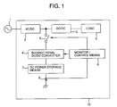
- Fig. 1 shows a block diagram of a DC backup power supply device in accordance with a first embodiment of the present invention.
- a power from a commercial AC power source 1 is converted to a DC power by an AC/DC converter 2 provided within an electric apparatus 10.
- the DC power is input to a DC/DC converter 3 having a voltage control function to be supplied to a load 4, forming a main circuit.
- a DC backup power supply device includes, as major constituent elements, a bi-directional DC/DC converter 6 connected to a DC path between the both converters of the main circuit via a switching means 5 and a DC power storage means 7 such as a secondary battery.
- a monitor/control means 8 is provided to input an electrical signal of a means 9 or the like for detecting a charging/discharging current of the DC power storage means 7 and to monitor and control an quantity of charging or discharging of the DC power storage means 7.
- Fig. 2 is a processing flowchart of a self-diagnosis procedure in the embodiment of Fig. 1.
- the embodiment is featured by the fact that the DC backup power supply detects and diagnoses its own fault. Explanation will first be made as to its self diagnosis procedure with use of Figs. 1 and 2.
- the switching means 5 is turned OFF to separate the DC backup power supply device from the main circuit.
- the bi-directional DC/DC converter 6 is controlled on the basis on a command from the monitor/control means 8 to perform discharging operation from the DC power storage means 7 to a smoothing capacitor (to be explained later) of the bi-directional DC/DC converter 6 connected to the side of the switching means 5.
- the device judges whether or not a discharging current flowed.
- the device determines in a step 204 that a discharger in the bi-directional DC/DC converter 6 became faulty. That is, of voltage step-up and step-down choppers, the voltage step-up chopper is faulty.
- the device judges that the discharger is normal and the backup power supply device can be connected to the main circuit without any problems.
- the device turns ON the switching means 5 to connect the DC backup power supply device to the main circuit.
- the device controls the bi-directional DC/DC converter 6 on the basis of a command from the monitor/control means 8 in a step 206 to perform charging operation over the DC power storage means 7 from the main circuit.
- the monitor/control means 8 judges whether or not a charging current flowed using an output of the means 9. When the charging current did not flow at all, the device determines in a step 208 that a charger in the bi-directional DC/DC converter 6 became faulty.
- the self diagnosis of the DC backup power supply device is completed.
- the device detects an abnormality in its own through the self diagnosis, the device records its abnormality location, turns OFF the switching means 5 or inhibits turning ON the switching means, and issues an alarm signal from an alarm device and/or lamp.
- the device is arranged so that the user when having recognized the alarm or lamp signal can recognize its abnormality location from the above record.
- a power supply device which can supply a DC power to a load with a high reliability and can have a self diagnosis function. Because the self diagnosis is carried out after the device is separated from the main circuit, the DC backup power supply device can diagnose each part in the device with a less possible danger of affecting the main circuit.
- Fig. 3 shows a first embodiment of a specific circuit of the DC backup power supply device in accordance with the present invention.
- the switching means 5 in Fig. 1 is implemented with an MOS FET 13 called a 'hot MOS' and a MOS FET driver circuit 14, while the monitor/control means 8 is implemented with use of, e.g., a microcomputer 20.
- the bi-directional DC/DC converter 6 comprises a voltage step-up/down chopper circuit which includes MOS FET's 151 and 152 for controlling the charging and discharging operation, a MOS FET driver circuit 16, a smoothing capacitor 17, and a reactor 18.
- the MOS FET 151 is a major constituent element of the voltage step-down chopper as a charger for charging a battery 19
- the MOS FET 152 is a major constituent element of the step-up chopper as a discharger for discharging the battery 19.
- the battery 19 as the DC power storage means 7 can employ a general secondary battery.
- the device can be made smaller in size.
- Fig. 4 shows a second embodiment of a specific circuit of the DC backup power supply device in accordance with the present invention.
- a second switching means battery MOS FET
- a driver circuit 22 for driving the second switching means and to be controlled by the microcomputer 20.
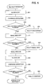
- Fig. 5 is a second embodiment of a processing flowchart of a self diagnosis procedure in the present invention. Explanation will be made as to the self diagnosis procedure with use of Figs. 4 and 5.
- the feature of the present embodiment is different from that of Fig. 2 in that procedures 501 to 504 for detecting an abnormality in the second switching means 21 under a condition that the first switching means (hot MOS) MOS FET 13 is turned OFF. Accordingly, the DC backup power supply device increases the number of items to be self diagnosed independently of the main circuit.
- the steps 201 to 204 are the same as those in Fig. 2.
- a next step 501 the battery MOS FET 21 is turned OFF to cause the discharging operation.
- the device or microcomputer judges in a step 502 whether or not a discharging current flowed.
- the control is shifted to the step 503 and the device determines that the battery MOS FET 21 is short-circuited as a fault.
- the device turns ON the battery MOS FET 21.
- the device executes the same procedure as the steps 205 to 208 in Fig. 2 and performs a diagnosis under a condition that the device is connected to the main circuit. Through such a series of operations, the self diagnosis is completed.
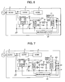
- Fig. 6 is a third embodiment of a specific circuit of the DC backup power supply device according to the present invention.
- the present embodiment is different from the embodiment of Fig. 4 in that a circuit 23 for detecting a total voltage (voltage across both terminals) of the battery 19 is provided and the detected voltage is applied to the microcomputer 20.
- the device upon diagnosis, the device can measure not only the charging/discharging currents of the battery in its charging, discharging and standby modes, but also the voltage of the battery.
- the deterioration diagnosis of the battery can be realized.
- the advanced deterioration of the battery causes the internal resistance to increase, so that battery life diagnosis criteria estimated from acceleration tests are previously provided.
- the device determines that the battery reached the end of its useful life and the device can report a diagnosis result of battery exchange to the user.
- Fig. 7 is a fourth embodiment of a specific circuit of the DC backup power supply device in accordance with the present invention.
- the present embodiment is different from the embodiment of Fig. 6 in that a voltage detecting circuit 231 for the battery 19 is arranged to measure voltages at a plurality of connection points of the battery.
- the device can measure not only the total voltage of the battery 19 but also intermediate voltages of battery cells connected in series.
- a fine short-circuit of the battery and a short-circuiting of each cell can be measured by connecting voltage detecting terminals for each cell, and thus a fault in each cell of the battery 19 can be detected.
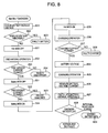
- Fig. 8 is a third embodiment of a processing flowchart of the self diagnosis procedure in accordance with the present invention. Explanation will be made as to the self diagnosis procedure with use of Figs. 7 and 8. The present embodiment is different from that of Fig. 5 in that steps 801 to 803 and steps 804 and 809 are added, which will be detailed later.
- a step 801 first of all, the device detects a voltage across a battery module with use of the voltage detecting circuit 231, judges in a step 802 the presence or absence of an abnormality in the voltage of each battery module, and detects in a step 803 a fault in cells in each battery module.
- a step 804 the device detects a battery voltage before the device is charged, and performs in a step 805 its charging operation from the main circuit to the battery 19 through the operation of the voltage step-down chopper.
- the device measures a charging current in a battery charge mode and a battery voltage after the device is charged. On the basis of these measured data, the device calculates an internal resistance of the battery 19 in a step 807.
- the device diagnose the life of the battery 19 depending on whether or not the calculated internal resistance of the battery 19 is higher than a specified internal resistance value.
- the device determines in a step 809 that the battery 19 reached the end of its useful life. In this case, the device reports a diagnosed result to the user to tell the battery exchange. Through such a series of operations, the self diagnosis can be realized.
- Fig. 9 is a fifth embodiment of a specific circuit of the DC backup power supply device in accordance with the present invention.
- the present embodiment is different from the embodiment of Fig. 7 in that a circuit 24 for detecting a voltage across the smoothing capacitor 17 was connected.
- the device can detect a fault in the MOS FET 13 as the first switching means.
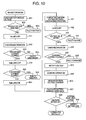
- Fig. 10 is a third embodiment of a processing flowchart of the self diagnosis procedure in accordance with the present invention.
- the present embodiment is different from the embodiment of Fig. 8 in that, in place of the step 205 in Fig. 8, a procedure for detecting a fault in the MOS FET 13 as the first switching means, that is, steps 101 to 104 are inserted.
- the first switching means 13 is turned OFF to separate the backup power supply device from the main circuit, under which condition the device controls the bi-directional DC/DC converter with a voltage value different from the DC path of the main circuit as a target.
- the target value of the discharging voltage to the smoothing capacitor 17 is set to be somewhat higher than the set voltage of the DC path to cause the bi-directional DC/DC converter to be discharged (operated as a voltage step-up chopper).
- the first switching means (MOS FET) 13 is turned ON.
- a voltage value detected by the voltage detecting circuit 24 after the MOS FET is turned ON varies from the above discharging-voltage target value to the voltage value of the DC path of the main circuit.
- the microcomputer 20 monitors the above voltage change in the step 103, the device can detect the present or absence of a fault in the MOS FET 13 in the step 104.
- the order of the battery voltage check, discharging operation, charging operation, battery deterioration diagnosis and MOS FET fault diagnosis is not limited to the illustrate order but may be arbitrarily set.
- the self diagnosis of the backup power supply device is first carried out under a condition that the first switching means 5 (FET 13) is turned OFF to confirm its normality. After the normality confirmation, when the self diagnosis of the backup power supply device is carried out under a condition that the first switching means 5 (FET 13) is turned ON, the likelihood of danger of exerting an adverse effect on the main circuit can be lessened.
- a DC backup power supply device which can supply a DC power to a load with a high reliability and also can have a self diagnosis function.
- the DC backup power supply device can diagnose each part in the device while lessening the likelihood of danger of exerting an adverse effect on the main circuit.
Landscapes
- Engineering & Computer Science (AREA)
- Power Engineering (AREA)
- Business, Economics & Management (AREA)
- Emergency Management (AREA)
- Charge And Discharge Circuits For Batteries Or The Like (AREA)
- Stand-By Power Supply Arrangements (AREA)
- Secondary Cells (AREA)
Applications Claiming Priority (2)
| Application Number | Priority Date | Filing Date | Title |
|---|---|---|---|
| JP2002113117 | 2002-04-16 | ||
| JP2002113117A JP3908077B2 (ja) | 2002-04-16 | 2002-04-16 | 直流バックアップ電源装置とその診断方法 |
Publications (3)
| Publication Number | Publication Date |
|---|---|
| EP1355403A2 true EP1355403A2 (fr) | 2003-10-22 |
| EP1355403A3 EP1355403A3 (fr) | 2006-08-23 |
| EP1355403B1 EP1355403B1 (fr) | 2008-08-13 |
Family
ID=28672607
Family Applications (1)
| Application Number | Title | Priority Date | Filing Date |
|---|---|---|---|
| EP20030008478 Expired - Lifetime EP1355403B1 (fr) | 2002-04-16 | 2003-04-11 | Alimentation de puissance de secours à courant continu et procédé pour diagnostiquer la même |
Country Status (5)
| Country | Link |
|---|---|
| US (1) | US7245469B2 (fr) |
| EP (1) | EP1355403B1 (fr) |
| JP (1) | JP3908077B2 (fr) |
| DE (1) | DE60322773D1 (fr) |
| TW (1) | TWI228853B (fr) |
Cited By (4)
| Publication number | Priority date | Publication date | Assignee | Title |
|---|---|---|---|---|
| EP2595279A1 (fr) * | 2011-11-18 | 2013-05-22 | Airbus Operations (Société par actions simplifiée) | Dispositif d'alimentation à découpage et aéronef comprenant au moins un tel dispositif |
| EP2733818A3 (fr) * | 2012-11-14 | 2015-08-12 | BAG engineering GmbH | Appareil de fonctionnement multifonctions destiné à l'alimentation d'un consommateur tel qu'un module LED et son procédé de fonctionnement |
| EP2632015A4 (fr) * | 2010-10-22 | 2016-11-30 | Emerson Network Power Co Ltd | Circuit de commande d'alimentation électrique sans coupure et alimentation électrique sans coupure associée |
| CN107579591A (zh) * | 2017-09-08 | 2018-01-12 | 华为技术有限公司 | 一种交流电源供电的备电系统 |
Families Citing this family (45)
| Publication number | Priority date | Publication date | Assignee | Title |
|---|---|---|---|---|
| JP3908076B2 (ja) * | 2002-04-16 | 2007-04-25 | 株式会社日立製作所 | 直流バックアップ電源装置 |
| JP3908077B2 (ja) | 2002-04-16 | 2007-04-25 | 株式会社日立製作所 | 直流バックアップ電源装置とその診断方法 |
| JP3776880B2 (ja) * | 2002-12-10 | 2006-05-17 | 株式会社日立製作所 | 無停電電源装置 |
| JP4227491B2 (ja) * | 2003-09-09 | 2009-02-18 | 株式会社リコー | デジタルカメラ用電源回路 |
| JP2005176461A (ja) * | 2003-12-09 | 2005-06-30 | Matsushita Electric Ind Co Ltd | 直流無停電電源装置 |
| JP4709497B2 (ja) * | 2004-04-08 | 2011-06-22 | 日立コンピュータ機器株式会社 | 電源バックアップ装置 |
| US20110121653A1 (en) * | 2005-02-18 | 2011-05-26 | O2Micro International Limited | Parallel powering of portable electrical devices |
| US7719236B2 (en) * | 2005-02-18 | 2010-05-18 | O2Micro International Limited | Parallel powering of portable electrical devices |
| US7529110B1 (en) * | 2005-05-20 | 2009-05-05 | American Power Conversion Corporation | Universal power adapter |
| US7466894B2 (en) * | 2005-05-23 | 2008-12-16 | Semiconductor Components Industries, L.L.C. | Power supply output monitor |
| DE102005027211A1 (de) * | 2005-06-13 | 2006-12-21 | Puls Gmbh | DC-Stromversorgung |
| DE102005030709A1 (de) * | 2005-06-29 | 2007-01-04 | Bosch Rexroth Ag | Stellantrieb und Notenergieversorgungseinrichtung |
| JP2007097252A (ja) * | 2005-09-27 | 2007-04-12 | Nayuta:Kk | 電源装置およびその双方向昇降圧コンバータ |
| US7802121B1 (en) * | 2006-03-27 | 2010-09-21 | Network Appliance, Inc. | Auxiliary power system |
| JP5074735B2 (ja) * | 2006-10-05 | 2012-11-14 | トヨタ自動車株式会社 | 緊急通報システム |
| US7928607B2 (en) * | 2007-03-29 | 2011-04-19 | Lamar Technologies Llc | Aircraft power system and apparatus for supplying power to an aircraft electrical system |
| US7723866B2 (en) * | 2007-08-14 | 2010-05-25 | Zippy Technology Corp. | Power backup system |
| US7952232B2 (en) * | 2008-03-13 | 2011-05-31 | General Electric Company | Wind turbine energy storage and frequency control |
| CN101630855B (zh) * | 2008-07-18 | 2011-09-28 | 海洋王照明科技股份有限公司 | 一种供电装置 |
| US8599589B2 (en) * | 2008-10-13 | 2013-12-03 | Apple Inc. | Methods and systems for reducing power consumption |
| JP5300059B2 (ja) * | 2009-02-13 | 2013-09-25 | エヌイーシーコンピュータテクノ株式会社 | 電源供給システム、その診断方法及びプログラム |
| DE102009003843A1 (de) * | 2009-04-28 | 2010-12-09 | Ssb Wind Systems Gmbh & Co. Kg | Verfahren zum Betreiben eines Rotorblattverstellantriebs |
| JP5493161B2 (ja) * | 2009-05-29 | 2014-05-14 | Dxアンテナ株式会社 | 状態監視型電源装置および電源状態監視方法 |
| CN102073021A (zh) * | 2009-11-24 | 2011-05-25 | 鸿富锦精密工业(深圳)有限公司 | 电源供应器测试装置 |
| CN103097984B (zh) * | 2010-09-16 | 2016-03-02 | 惠普发展公司,有限责任合伙企业 | 功率封顶系统 |
| JP2012152035A (ja) * | 2011-01-19 | 2012-08-09 | Sharp Corp | 電気自動車充電装置、電気自動車充電方法、プログラムおよび記録媒体 |
| CN103492222B (zh) * | 2011-04-22 | 2016-01-20 | 三菱电机株式会社 | 充电装置 |
| JP5658360B2 (ja) | 2011-05-10 | 2015-01-21 | 三菱電機株式会社 | 直流電源装置および電力変換方法 |
| US20130187468A1 (en) | 2012-01-24 | 2013-07-25 | Google Inc. | Uninterruptible power supply control in distributed power architecture |
| JP6167350B2 (ja) * | 2012-01-27 | 2017-07-26 | エリーパワー株式会社 | 電源装置、電源装置の制御方法およびプログラム |
| KR101607799B1 (ko) * | 2012-03-27 | 2016-03-30 | 미쓰비시덴키 가부시키가이샤 | 축전 디바이스의 수명 진단 방법 |
| WO2014012120A1 (fr) * | 2012-07-13 | 2014-01-16 | Inertech Ip Llc | Systèmes et procédés électriques à faible consommation d'énergie pour centres informatiques modulaires et capsules de données modulaires |
| US9490663B1 (en) * | 2012-07-16 | 2016-11-08 | Google Inc. | Apparatus and methodology for battery backup circuit and control in an uninterruptible power supply |
| JP5611302B2 (ja) * | 2012-10-01 | 2014-10-22 | 三菱電機株式会社 | 電源装置および電源装置の異常判定方法 |
| WO2014057298A1 (fr) * | 2012-10-11 | 2014-04-17 | American Power Conversion Corporation | Circuit et procédé pour fournir une alimentation électrique sans coupure |
| CN103296641A (zh) * | 2013-06-04 | 2013-09-11 | 中国电子科技集团公司第四十五研究所 | 一种电机驱动系统的电源掉电保护装置 |
| CN103296733B (zh) * | 2013-06-08 | 2015-02-18 | 中达电通股份有限公司 | 直流供电系统中电池组供电回路状态的监测方法 |
| CN104811020A (zh) * | 2014-01-27 | 2015-07-29 | 台达电子企业管理(上海)有限公司 | 电源系统及供电方法 |
| US10931190B2 (en) | 2015-10-22 | 2021-02-23 | Inertech Ip Llc | Systems and methods for mitigating harmonics in electrical systems by using active and passive filtering techniques |
| US10524393B2 (en) * | 2016-05-20 | 2019-12-31 | YouSolar, Inc. | Multi-module electrical system containing with an integral air duct |
| US10205340B2 (en) | 2017-01-03 | 2019-02-12 | Cyber Power Systems Inc. | Un-interruptible power supply with indication of battery internal resistance |
| US11594883B2 (en) * | 2018-01-23 | 2023-02-28 | Tdk Corporation | Direct current power supplying system |
| KR101918253B1 (ko) * | 2018-01-26 | 2018-11-13 | 최운선 | 플라즈마 전원장치의 자가진단모듈 및 자가진단방법 |
| NL2026052B1 (en) * | 2020-07-13 | 2022-03-15 | Eldolab Holding Bv | Auxiliary battery circuit for an LED driver |
| EP4503381A4 (fr) * | 2022-03-28 | 2025-07-02 | Panasonic Energy Co Ltd | Alimentation électrique de secours |
Family Cites Families (10)
| Publication number | Priority date | Publication date | Assignee | Title |
|---|---|---|---|---|
| JPH0196743A (ja) | 1987-10-09 | 1989-04-14 | Mitsubishi Electric Corp | モニタ装置 |
| US5019717A (en) * | 1988-11-14 | 1991-05-28 | Elegant Design Solutions Inc. | Computer-controlled uninterruptable power supply |
| US5458991A (en) * | 1993-05-19 | 1995-10-17 | Sl Waber, Inc. | UPS with auto self test |
| CA2151684A1 (fr) * | 1994-06-30 | 1995-12-31 | David L. Aldridge | Systeme de commutation d'alimentation et de detection des defaillances |
| JP3345793B2 (ja) * | 1995-08-28 | 2002-11-18 | 日本電算設備株式会社 | 無停電電源装置の異常検出装置 |
| JPH10309045A (ja) * | 1997-05-07 | 1998-11-17 | Sony Corp | 予備電源装置 |
| JP2000197347A (ja) * | 1998-12-25 | 2000-07-14 | Hitachi Ltd | 電源装置 |
| JP2002369407A (ja) * | 2001-06-06 | 2002-12-20 | Hitachi Ltd | ピークカット機能付きバックアップ電源 |
| JP3908076B2 (ja) | 2002-04-16 | 2007-04-25 | 株式会社日立製作所 | 直流バックアップ電源装置 |
| JP3908077B2 (ja) | 2002-04-16 | 2007-04-25 | 株式会社日立製作所 | 直流バックアップ電源装置とその診断方法 |
-
2002
- 2002-04-16 JP JP2002113117A patent/JP3908077B2/ja not_active Expired - Fee Related
-
2003
- 2003-04-11 DE DE60322773T patent/DE60322773D1/de not_active Expired - Fee Related
- 2003-04-11 EP EP20030008478 patent/EP1355403B1/fr not_active Expired - Lifetime
- 2003-04-14 US US10/412,319 patent/US7245469B2/en not_active Expired - Fee Related
- 2003-04-15 TW TW92108701A patent/TWI228853B/zh not_active IP Right Cessation
Cited By (7)
| Publication number | Priority date | Publication date | Assignee | Title |
|---|---|---|---|---|
| EP2632015A4 (fr) * | 2010-10-22 | 2016-11-30 | Emerson Network Power Co Ltd | Circuit de commande d'alimentation électrique sans coupure et alimentation électrique sans coupure associée |
| US9570930B2 (en) | 2010-10-22 | 2017-02-14 | Emerson Netwrok Power Co., Ltd. | UPS electricity supply control circuit and UPS electricity supply |
| EP2595279A1 (fr) * | 2011-11-18 | 2013-05-22 | Airbus Operations (Société par actions simplifiée) | Dispositif d'alimentation à découpage et aéronef comprenant au moins un tel dispositif |
| FR2983005A1 (fr) * | 2011-11-18 | 2013-05-24 | Airbus Operations Sas | Dispositif d'alimentation a decoupage et aeronef comprenant au moins un tel dispositif |
| US9112369B2 (en) | 2011-11-18 | 2015-08-18 | Airbus Operations Sas | Switched-mode power supply device and aircraft including at least one such device |
| EP2733818A3 (fr) * | 2012-11-14 | 2015-08-12 | BAG engineering GmbH | Appareil de fonctionnement multifonctions destiné à l'alimentation d'un consommateur tel qu'un module LED et son procédé de fonctionnement |
| CN107579591A (zh) * | 2017-09-08 | 2018-01-12 | 华为技术有限公司 | 一种交流电源供电的备电系统 |
Also Published As
| Publication number | Publication date |
|---|---|
| EP1355403A3 (fr) | 2006-08-23 |
| JP3908077B2 (ja) | 2007-04-25 |
| TW200404397A (en) | 2004-03-16 |
| EP1355403B1 (fr) | 2008-08-13 |
| TWI228853B (en) | 2005-03-01 |
| US20030231009A1 (en) | 2003-12-18 |
| JP2003309934A (ja) | 2003-10-31 |
| DE60322773D1 (de) | 2008-09-25 |
| US7245469B2 (en) | 2007-07-17 |
Similar Documents
| Publication | Publication Date | Title |
|---|---|---|
| EP1355403B1 (fr) | Alimentation de puissance de secours à courant continu et procédé pour diagnostiquer la même | |
| US11774499B2 (en) | Relay diagnosis device, relay diagnosis method, battery system, and electric vehicle | |
| US12074465B2 (en) | Control device, electric storage device, electric storage system, and computer-readable medium | |
| EP1837944B1 (fr) | Appareil de contrôle d'alimentation électrique | |
| JP2021511768A (ja) | スイッチ診断装置及び方法 | |
| US20110307733A1 (en) | Electrical charge and discharge circuit, and an embedded controller | |
| EP2632021A1 (fr) | Système de batteries | |
| CN107850643A (zh) | 用于诊断开关元件的故障的装置和方法 | |
| JP5092812B2 (ja) | 組電池の監視装置および故障診断方法 | |
| JP2009069056A (ja) | 多セル直列電池用のセル電圧異常検出装置及びセル電圧監視装置 | |
| KR20140103773A (ko) | 셀 밸런싱 회로의 고장 진단 장치 및 방법 | |
| EP4549968B1 (fr) | Appareil de diagnostic de batterie, procédé de diagnostic de batterie, bloc-batterie et véhicule | |
| KR101858321B1 (ko) | 셀 밸런싱 회로의 고장 진단 장치 및 방법 | |
| KR20210041981A (ko) | 배터리 팩의 진단 방법, 배터리 관리 시스템 및 배터리 장치 | |
| JP7680141B2 (ja) | バッテリー診断方法、その方法を提供するバッテリー診断装置、およびバッテリーシステム | |
| KR20200088153A (ko) | 전류 센서 진단 장치 및 이를 포함하는 배터리 팩 | |
| CN114303273B (zh) | 电池管理设备和包括该电池管理设备的电池组 | |
| US12429522B2 (en) | Relay diagnosis device and relay diagnosis method | |
| KR102839450B1 (ko) | 배터리 장치 및 드리프트 오류 진단 방법 | |
| EP4102245B1 (fr) | Appareil de batterie et procédé de diagnostic de capteur de courant | |
| JP4147589B2 (ja) | バッテリー寿命予測装置とこれを用いた電源装置 | |
| EP4700407A1 (fr) | Système de gestion de batterie, dispositif de batterie et procédé de diagnostic d'une ligne de mesure de tension d'élément | |
| KR102945610B1 (ko) | 배터리 충방전 시험 장치 및 이를 이용한 충방전 시험 방법 | |
| JPH10224986A (ja) | 直流電力供給装置及びその制御方法 | |
| JPH08221159A (ja) | 二次電池故障検出回路及び二次電池故障監視装置 |
Legal Events
| Date | Code | Title | Description |
|---|---|---|---|
| PUAI | Public reference made under article 153(3) epc to a published international application that has entered the european phase |
Free format text: ORIGINAL CODE: 0009012 |
|
| AK | Designated contracting states |
Kind code of ref document: A2 Designated state(s): AT BE BG CH CY CZ DE DK EE ES FI FR GB GR HU IE IT LI LU MC NL PT RO SE SI SK TR |
|
| AX | Request for extension of the european patent |
Extension state: AL LT LV MK |
|
| 17P | Request for examination filed |
Effective date: 20060331 |
|
| PUAL | Search report despatched |
Free format text: ORIGINAL CODE: 0009013 |
|
| AK | Designated contracting states |
Kind code of ref document: A3 Designated state(s): AT BE BG CH CY CZ DE DK EE ES FI FR GB GR HU IE IT LI LU MC NL PT RO SE SI SK TR |
|
| AX | Request for extension of the european patent |
Extension state: AL LT LV MK |
|
| 17Q | First examination report despatched |
Effective date: 20061211 |
|
| AKX | Designation fees paid |
Designated state(s): DE FR GB |
|
| GRAP | Despatch of communication of intention to grant a patent |
Free format text: ORIGINAL CODE: EPIDOSNIGR1 |
|
| GRAS | Grant fee paid |
Free format text: ORIGINAL CODE: EPIDOSNIGR3 |
|
| GRAA | (expected) grant |
Free format text: ORIGINAL CODE: 0009210 |
|
| AK | Designated contracting states |
Kind code of ref document: B1 Designated state(s): DE FR GB |
|
| REG | Reference to a national code |
Ref country code: GB Ref legal event code: FG4D |
|
| REF | Corresponds to: |
Ref document number: 60322773 Country of ref document: DE Date of ref document: 20080925 Kind code of ref document: P |
|
| PLBE | No opposition filed within time limit |
Free format text: ORIGINAL CODE: 0009261 |
|
| STAA | Information on the status of an ep patent application or granted ep patent |
Free format text: STATUS: NO OPPOSITION FILED WITHIN TIME LIMIT |
|
| PGFP | Annual fee paid to national office [announced via postgrant information from national office to epo] |
Ref country code: GB Payment date: 20090220 Year of fee payment: 7 |
|
| 26N | No opposition filed |
Effective date: 20090514 |
|
| PGFP | Annual fee paid to national office [announced via postgrant information from national office to epo] |
Ref country code: FR Payment date: 20090226 Year of fee payment: 7 |
|
| PGFP | Annual fee paid to national office [announced via postgrant information from national office to epo] |
Ref country code: DE Payment date: 20090626 Year of fee payment: 7 |
|
| REG | Reference to a national code |
Ref country code: GB Ref legal event code: 732E Free format text: REGISTERED BETWEEN 20100204 AND 20100211 |
|
| REG | Reference to a national code |
Ref country code: FR Ref legal event code: TP |
|
| GBPC | Gb: european patent ceased through non-payment of renewal fee |
Effective date: 20100411 |
|
| REG | Reference to a national code |
Ref country code: FR Ref legal event code: ST Effective date: 20101230 |
|
| PG25 | Lapsed in a contracting state [announced via postgrant information from national office to epo] |
Ref country code: FR Free format text: LAPSE BECAUSE OF NON-PAYMENT OF DUE FEES Effective date: 20100430 |
|
| PG25 | Lapsed in a contracting state [announced via postgrant information from national office to epo] |
Ref country code: DE Free format text: LAPSE BECAUSE OF NON-PAYMENT OF DUE FEES Effective date: 20101103 |
|
| PG25 | Lapsed in a contracting state [announced via postgrant information from national office to epo] |
Ref country code: GB Free format text: LAPSE BECAUSE OF NON-PAYMENT OF DUE FEES Effective date: 20100411 |