EP1355832B1 - Bouchage inviolable - Google Patents
Bouchage inviolable Download PDFInfo
- Publication number
- EP1355832B1 EP1355832B1 EP02703588A EP02703588A EP1355832B1 EP 1355832 B1 EP1355832 B1 EP 1355832B1 EP 02703588 A EP02703588 A EP 02703588A EP 02703588 A EP02703588 A EP 02703588A EP 1355832 B1 EP1355832 B1 EP 1355832B1
- Authority
- EP
- European Patent Office
- Prior art keywords
- tamper
- lid
- edge
- band
- evident band
- Prior art date
- Legal status (The legal status is an assumption and is not a legal conclusion. Google has not performed a legal analysis and makes no representation as to the accuracy of the status listed.)
- Expired - Lifetime
Links
- 239000000463 material Substances 0.000 description 4
- 229920003023 plastic Polymers 0.000 description 4
- 239000004033 plastic Substances 0.000 description 4
- 230000000284 resting effect Effects 0.000 description 3
- 230000000295 complement effect Effects 0.000 description 2
- 230000009977 dual effect Effects 0.000 description 1
- 238000001746 injection moulding Methods 0.000 description 1
- 230000000452 restraining effect Effects 0.000 description 1
- 239000000243 solution Substances 0.000 description 1
- XLYOFNOQVPJJNP-UHFFFAOYSA-N water Substances O XLYOFNOQVPJJNP-UHFFFAOYSA-N 0.000 description 1
Images


Classifications
-
- B—PERFORMING OPERATIONS; TRANSPORTING
- B65—CONVEYING; PACKING; STORING; HANDLING THIN OR FILAMENTARY MATERIAL
- B65D—CONTAINERS FOR STORAGE OR TRANSPORT OF ARTICLES OR MATERIALS, e.g. BAGS, BARRELS, BOTTLES, BOXES, CANS, CARTONS, CRATES, DRUMS, JARS, TANKS, HOPPERS, FORWARDING CONTAINERS; ACCESSORIES, CLOSURES, OR FITTINGS THEREFOR; PACKAGING ELEMENTS; PACKAGES
- B65D47/00—Closures with filling and discharging, or with discharging, devices
- B65D47/04—Closures with discharging devices other than pumps
- B65D47/06—Closures with discharging devices other than pumps with pouring spouts or tubes; with discharge nozzles or passages
- B65D47/08—Closures with discharging devices other than pumps with pouring spouts or tubes; with discharge nozzles or passages having articulated or hinged closures
- B65D47/0804—Closures with discharging devices other than pumps with pouring spouts or tubes; with discharge nozzles or passages having articulated or hinged closures integrally formed with the base element provided with the spout or discharge passage
- B65D47/0833—Hinges without elastic bias
- B65D47/0838—Hinges without elastic bias located at an edge of the base element
-
- B—PERFORMING OPERATIONS; TRANSPORTING
- B65—CONVEYING; PACKING; STORING; HANDLING THIN OR FILAMENTARY MATERIAL
- B65D—CONTAINERS FOR STORAGE OR TRANSPORT OF ARTICLES OR MATERIALS, e.g. BAGS, BARRELS, BOTTLES, BOXES, CANS, CARTONS, CRATES, DRUMS, JARS, TANKS, HOPPERS, FORWARDING CONTAINERS; ACCESSORIES, CLOSURES, OR FITTINGS THEREFOR; PACKAGING ELEMENTS; PACKAGES
- B65D2401/00—Tamper-indicating means
- B65D2401/15—Tearable part of the closure
- B65D2401/25—Non-metallic tear-off strips
Definitions
- the invention concerns the technical field of caps with a dispensing orifice for closing the neck of a container.
- a cap made of plastics material which comprises an upper part having a dispensing orifice for dispensing the contents of the bottle.
- the cap also comprises a substantially cylindrical skirt extending from the upper part and having on an inner face means of fixing it on to the neck of the bottle.
- the cap comprises in addition a lid connected to the upper part by at least one hinge in order to be movable between an open position and a closed position of the dispensing orifice.
- the cap comprises in addition a tamper-evident band generally situated opposite the hinge and connected to the upper part of the cap by at least two frangible straps each having a zone of least resistance for rupture.
- the tamper-evident band then defines a hooking edge for a hook carried by the lid.
- such a cap is made of plastics material injected in a mould which allows a monobloc cap to be obtained with an open configuration of the lid of the dispensing orifice.
- the lid is placed in the closed position covering the dispensing orifice, a position in which the hook of the lid is engaged under the hooking edge defined by the tamper-evident band.
- a cap such as the above enables the hermetic closure of a container to be ensured while more often than not guaranteeing the integrity of the contents of the container before first opening of the lid of the cap.
- the user has to get rid of the tamper-evident band, which is no longer of any use to him. So, apart from leaving the tamper-evident band on the ground, the user has to have at his disposal means for temporarily storing the tamper-evident band or a dustbin. The user does not always have such means at his disposal.
- the invention concerns a cap with a dispensing orifice for closing the neck of a container, comprising:
- the cap is characterised in that the lid includes means for retaining the tamper-evident band in order to hold it against the lid in the closed position of the orifice and to prevent manipulation of the band to open the lid without rupture of the straps.
- the retaining means are adapted to receive at least part of the edge of the band situated opposite the hooking edge in order to hold the band on the lid after a rupture of the straps following a first opening of the lid.
- the retaining means therefore serve a dual purpose. First, they help to prevent manipulation of the band aimed at defeating the tamper-evidence. Second, they retain the band on the cap after first opening.
- the retaining means comprise at least one and preferably two seats for receiving at least a part of the tamper-evident band in order, in association with the hook of the lid, to retain the tamper-evident band on the lid after a rupture of the straps following a first opening of the lid.
- the two seats each then receive, on the one hand, a part of the edge of the band situated opposite the hooking edge and, on the other hand, an extreme end of the tamper-evident band.
- the retaining means comprise at least one groove designed to receive at least a part of the edge of the tamper-evident band situated opposite the hooking edge, when the hook of the lid is engaged under the hooking edge.
- the retaining means comprise at least one tab which fits over a part of the edge situated opposite the hooking edge of the tamper-evident band.
- the tamper-evident band in order to facilitate engagement of the retaining means on the tamper-evident band at the time of first opening of the lid, comprises a notch arranged in the edge of the band situated opposite the hooking edge.
- the tamper-evident band has a notch level with the hooking edge.
- the tamper-evident band comprises a window, the edge of which defines the hooking edge of the hook of the lid.
- a cap according to the invention designated as a whole by the reference 1, comprises a pourer part A and a lid part B.
- the pourer part A comprises an upper part 2 from which extends a skirt 3 of more or less cylindrical shape with respect to the main longitudinal axis X-X' (see Fig.2).
- the skirt 3 has, on its inner face, means 4 for fixing the cap 1 on to a neck 5 of a container 6.
- the means 4 for fixing the skirt 3 are designed to co-operate with complementary means 7 offered by the outer face of the neck 5.
- the fixing means 4 and 7 can be realised in any appropriate way and, according to the example illustrated, are constituted by a rib 4 of the skirt 3 designed to snap into a complementary groove 7 of the neck.
- the fixing means 4 and 7 could be realised in any other way such as, for example, one or several helical threads allowing screwing of the cap 1 on to the neck 5.
- a dispensing orifice 10 is arranged in the upper part 2 in order to allow dispensing of the contents of the container 6.
- the dispensing orifice 10 is defined by a collar 1 extending from the upper part 2 opposite the skirt 3.
- the orifice 10 is equipped with an anti-splash device 12.
- the cap 1 comprises in addition a lid 15 connected to the upper part 2, level with a joining edge between the upper part 2 and the skirt 3, by at least one hinge and, according to the example illustrated, two hinges 16 and 17.
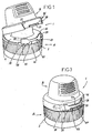
- the lid 15 is thereby movable between an open position of the orifice 10 as illustrated in Fig.2 and a closed position of closure of the orifice 10 such as illustrated more particularly in Fig.3.
- the lid 15 is equipped, on its inner face 18, with means 20 designed to ensure a more or less tight closure of the orifice 10.
- the means 20 are formed by two concentric closure skirts 21 and 22 designed to co-operate with the inner and outer edges of the collar 11.
- the cap 1 also comprises a tamper-evident band 25 which defines a hooking edge 26 for a hook 27 arranged on the outer face of the lid 15.
- the hook 27 is arranged on the lid 15 opposite the hinges 16 and 17 while the band 25 is situated bordering on the edge of the upper part 2 also opposite the hinges 16 and 17.
- the band 25 extends, moreover, over one side only of the circumference of the upper part.
- the tamper-evident band 25 is connected to the edge of the upper part 2 by two series of divisible straps 28 and 29 on either side of the hooking edge 26.
- Each series 28 and 29 comprises at least two divisible straps, of which one 30, the outer strap, is situated close to one end 39 of the band 25 and a second 32, the inner strap, is situated close to the hooking edge 26.
- the lid 15 comprises means 35 for retaining the tamper-evident band in order to hold the band on the lid after a rupture of the straps 30, 32 following a first opening of the cap.
- the means 35 for retaining the tamper-evident band can be realised in any appropriate way.
- the means 35 partly receive at least the edge 36 of the tamper-evident band 25 situated opposite the hooking edge 26.
- the retaining means comprise two seats 37, 38, which are situated on either side of the hook 27. Each seat 37, 38 is designed to receive an end of the tamper-evident band.
- each seat 37 or 38 fits a part of the edge 36 of the band situated opposite hooking the edge 26 as well as a far end 39 of the tamper-evident band.
- the retaining means 35 formed by the two lateral seats 38 and 37, ensure their function of retaining the tamper-evident band 25 in the following way.
- the cap in conformity with the invention is made of plastics material by injection moulding in the open configuration illustrated in Fig.2. After removal from the mould and before use of the cap, the lid is placed in closed position of the orifice 10 such as illustrated in Fig.3 in which the hook 27 is engaged under the edge 26 of the tamper-evident band.
- the seats 37 and 38 engage on the ends 39 of the tamper-evident band.
- the edge 36 of the tamper-evident band has a notch 40 which allows the ends of the tamper-evident band 25 to begin to engage in the seats 37 and 38 before the hook 27 comes to rest on the tamper-evident band in the course of the descent of the lid 15 towards the upper part 2.
- the tamper-evident band 25 is, on the one hand, connected to the upper part 2 by the straps 30 and 32 and, on the other hand, immobilised in the seats 37 and 38 in such a way that it is not possible to pull down the tamper-evident band towards the front in the direction of the arrow Fl in order to try to open the lid 15 without rupture of the straps.
- the closure of the present invention therefore restricts the ability to manipulate the band, first by physically restraining its movement, and second by restricting the area of the band that can be accessed. Moreover, after a first opening of the cap according to the invention by rupture of the divisible straps 30 and 32, the tamper-evident band remains attached to the lid 15 as shown in Fig.6. In fact, the ends 39 of the tamper-evident band are immobilised in the seats 37 and 38 while the hooking edge remains resting on the hook 27 of the lid. In this way, the tamper-evident band remains attached to the lid 15, so that the question of its being taken care of or its storage no longer arises for a user of the cap.
- the immobilisation of the tamper-evident band results, on the one hand from the resting of the hooking edge 26 on the hook 27 and, on the other hand, from a resting of the edge 36 of the tamper-evident band 25 against the edges of the seats 37 and 38.
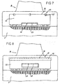
- Fig.7 illustrates an embodiment according to which the retaining means 35 are constituted by at least one, and according to the example illustrated, three tabs 45 which fit over the upper edge 36 of the tamper-evident band.
- the retaining means 35 hold the band 25 against the lid 15 in the closed position of the orifice and prevent movement of the band 25 towards the front in order to try to release the hook 27 without rupture of the straps.
- the top edge of the tamper-evident band is not notched.
- providing tabs on the sides of the band 25 could also be considered.
- Fig.8 illustrates an embodiment of the retaining means according to which the latter are constituted by a continuous groove 46 fitting the upper edge 36 of the tamper-evident band.
- the tamper-evident band 25 has a window 47 into which the hook 27 is inserted, the top edge of the window defining the hooking edge 26 for the hook 27.
- the skirt 3 does not include a tamper-evident band, which of course it could.
Landscapes
- Engineering & Computer Science (AREA)
- Mechanical Engineering (AREA)
- Closures For Containers (AREA)
- Seal Device For Vehicle (AREA)
- Pharmaceuticals Containing Other Organic And Inorganic Compounds (AREA)
- Saccharide Compounds (AREA)
Claims (10)
- Bouchon doté d'un orifice distributeur pour fermer le goulot (5) d'un récipient (6), comprenant :- une pièce supérieure (2) comportant un orifice distributeur (10) pour distribuer le contenu du récipient ;- une jupe (3) pendant à la pièce supérieure (2) et comportant un moyen (4) pour fixer le bouchon sur le goulot (5) du récipient,- un couvercle (15) relié à la pièce supérieure par au moins une articulation (16) pour pouvoir être mobile entre des positions ouverte et fermée de l'orifice distributeur (10) ;- une bande inviolable (25) qui est reliée à la pièce supérieure (2) du bouchon par au moins deux brides cassables (30, 32) comportant chacune une zone de moindre résistance pour la rupture, et qui définit un bord d'accrochage (26) dans la position fermée de l'orifice pour recevoir un crochet (27) supporté par le couvercle (15),caractérisé en ce que
le couvercle comprend un moyen (35) pour retenir la bande inviolable (25) afin de la garder contre le couvercle (15) dans la position fermée de l'orifice (10) et d'empêcher une manipulation de la bande pour ouvrir le couvercle sans rupture des brides. - Bouchon selon la revendication 1, caractérisé en ce que le moyen de retenue (35) est adapté à recevoir au moins une partie d'un bord (36) de la bande (25) situé à l'opposé du bord d'accrochage (26) afin de retenir la bande inviolable (25) sur le couvercle (15) après une rupture des brides postérieurement à une première ouverture du couvercle (15).
- Bouchon selon la revendication 1 ou 2, caractérisé en ce que le moyen de retenue (35) comprend au moins un siège (37) pour recevoir au moins une partie de la bande inviolable (25) afin de, en association avec le crochet (27) du couvercle, garder la bande inviolable (25) sur le couvercle après une rupture des brides postérieurement à une première ouverture du couvercle.
- Bouchon selon la revendication 3, caractérisé en ce que le moyen de retenue (35) comprend deux sièges (37, 38) situés sur chaque côté du crochet (27) et conçus chacun pour recevoir une extrémité (39) de la bande inviolable (25) .
- Bouchon selon la revendication 4, caractérisé en ce que les deux sièges (37, 38) épousent chacun une partie du bord de la bande situé à l'opposé du bord d'accrochage et une extrémité lointaine de la bande inviolable.
- Bouchon selon la revendication 1 ou 2, caractérisé en ce que le moyen de retenue (35) comprend au moins une rainure (46) conçue pour recevoir au moins une partie d'un bord (36) de la bande inviolable (25), situé à l'opposé du bord d'accrochage (26) lorsque le crochet (27) du couvercle est engagé sous le bord d'accrochage (26).
- Bouchon selon la revendication 1 ou 2, caractérisé en ce que le moyen de retenue comprend au moins une patte (45), qui s'emboîte sur une partie du bord (36) situé à l'opposé du bord d'accrochage (26) de la bande inviolable.
- Bouchon selon l'une quelconque des revendications 1 à 7, caractérisé en ce que la bande inviolable comprend une entaille (40) agencée dans le bord (36) de la bande situé à l'opposé du bord d'accrochage (26).
- Bouchon selon l'une quelconque des revendications 1 à 8, caractérisé en ce que la bande inviolable (25) comporte une entaille de niveau avec le bord d'accrochage (26) .
- Bouchon selon l'une quelconque des revendications 1 à 9, caractérisé en ce que la bande inviolable (25) comprend une fenêtre (47) dont un bord définit le bord d'accrochage (26) du crochet (27) du couvercle (15).
Applications Claiming Priority (3)
| Application Number | Priority Date | Filing Date | Title |
|---|---|---|---|
| FR0101252A FR2820120A1 (fr) | 2001-01-30 | 2001-01-30 | Bouchon avec orifice verseur ferme par un couvercle et systeme d'inviolabilite du couvercle |
| FR0101252 | 2001-01-30 | ||
| PCT/EP2002/000949 WO2002060776A1 (fr) | 2001-01-30 | 2002-01-30 | Bouchage inviolable |
Publications (2)
| Publication Number | Publication Date |
|---|---|
| EP1355832A1 EP1355832A1 (fr) | 2003-10-29 |
| EP1355832B1 true EP1355832B1 (fr) | 2006-03-22 |
Family
ID=8859413
Family Applications (1)
| Application Number | Title | Priority Date | Filing Date |
|---|---|---|---|
| EP02703588A Expired - Lifetime EP1355832B1 (fr) | 2001-01-30 | 2002-01-30 | Bouchage inviolable |
Country Status (6)
| Country | Link |
|---|---|
| US (1) | US6976607B2 (fr) |
| EP (1) | EP1355832B1 (fr) |
| AT (1) | ATE320981T1 (fr) |
| DE (1) | DE60210044T2 (fr) |
| FR (1) | FR2820120A1 (fr) |
| WO (1) | WO2002060776A1 (fr) |
Families Citing this family (53)
| Publication number | Priority date | Publication date | Assignee | Title |
|---|---|---|---|---|
| FR2848992B1 (fr) * | 2002-12-23 | 2005-08-19 | Seaquist General Plastics | Dispositif d'obturation pour ouverture de recipient. |
| GB2401859A (en) * | 2003-04-17 | 2004-11-24 | Portola Packaging Ltd | Closure with integral spaced hinge portions |
| ITMI20040663A1 (it) * | 2004-04-01 | 2004-07-01 | Guglielmo Ferrari | Tappo di chiusura da avvitare su un collo a vite di un recipiente |
| FR2870215B1 (fr) | 2004-05-17 | 2007-08-10 | Valois Sas | Capot pour tete de distribution de produit fluide. |
| AU2005279146B2 (en) * | 2004-09-01 | 2010-12-23 | Creanova Universal Closures Ltd. | Tamper evidence means for a closure and a tamper evident closure |
| WO2006026836A1 (fr) * | 2004-09-07 | 2006-03-16 | Marcel Van Ryn | Bouchon indicateur d'ouverture |
| AU2005282233B2 (en) * | 2004-09-07 | 2011-09-01 | Marcel Van Ryn | Tamper indicative closure |
| JP4863658B2 (ja) * | 2005-06-30 | 2012-01-25 | 天龍化学工業株式会社 | 液体容器用の蓋装置 |
| AR056770A1 (es) * | 2005-11-15 | 2007-10-24 | Bayer Consumer Care Ag | Cierre de garantia |
| US7810663B2 (en) * | 2006-04-11 | 2010-10-12 | John Young | Tamper-evident closure |
| RU2407684C2 (ru) * | 2006-05-19 | 2010-12-27 | Сиквист-Леффлер Кунстштоффверк Гмбх | Способ изготовления укупорочного приспособления для емкости |
| WO2007134618A1 (fr) | 2006-05-19 | 2007-11-29 | Seaquist-Löffler Kunststoffwerk Gmbh | Dispositif de fermeture pour un récipient et procédé de fabrication d'un tel dispositif de fermeture |
| EP2089290A2 (fr) * | 2006-11-15 | 2009-08-19 | Bericap | Couvercle a charniere pivotante dotee d' un element de garantie de l'integrite |
| GB0700090D0 (en) * | 2007-01-04 | 2007-02-07 | Obrist Closures Switzerland | A closure |
| ITAL20070003A1 (it) * | 2007-01-12 | 2008-07-13 | Gefit Spa | Chiusura a capsula per contenitori flessibili di liquidi |
| EP2505267B1 (fr) * | 2007-04-23 | 2019-06-26 | Silgan Dispensing Systems Corporation | Protection inviolable pour buse et procédés d'utilisation |
| US8292101B1 (en) | 2007-05-29 | 2012-10-23 | Remax Healthcare Packaging Inc. | Flip-top dispensing system with a child resistant latch mechanism |
| US7861873B1 (en) * | 2007-05-29 | 2011-01-04 | Rexam Closures And Containers Inc. | Flip-top dispensing system with a child resistant latch mechanism |
| GB0721330D0 (en) * | 2007-10-31 | 2007-12-12 | Obrist Closures Switzerland | Tamper Evident closure |
| DE102007056380B4 (de) * | 2007-11-22 | 2020-06-25 | WestRock Dispensing Systems Hemer GmbH | Verschlusskappe für einen Austragkopf |
| FR2928351B1 (fr) * | 2008-03-05 | 2011-01-21 | Tetra Laval Holdings & Finance | Dispositif de bouchage d'un col de recipient. |
| BRPI0904284A2 (pt) | 2009-10-30 | 2011-06-28 | Fechamentos Inteligentes Desenvolvimento De Embalagens Ltda | fechamento de segurança com trava, e, sistema de fixação de fechamento de segurança |
| US8646633B2 (en) * | 2009-12-16 | 2014-02-11 | Johnson & Johnson Vision Care Inc | Closure for containers of ophthalmic solutions containing a spout cap |
| CA142207S (en) * | 2011-03-10 | 2012-09-10 | Tetra Laval Holdings & Finance | Cap |
| US9546027B2 (en) * | 2011-05-10 | 2017-01-17 | The Clorox Company | Irremovable closure |
| GB2490687B (en) * | 2011-05-10 | 2014-10-01 | Clorox Co | A closure |
| CA143361S (en) * | 2011-05-30 | 2012-09-10 | Tetra Laval Holdings & Finance | Cap |
| CA143360S (en) * | 2011-05-30 | 2012-09-10 | Tetra Laval Holdings & Finance | Cap |
| CA143362S (en) * | 2011-05-30 | 2012-09-10 | Tetra Laval Holdings & Finance | Cap |
| CA143359S (en) * | 2011-05-30 | 2012-09-10 | Tetra Laval Holdings & Finance | Cap |
| CA143358S (en) * | 2011-05-30 | 2012-09-10 | Tetra Laval Holdings & Finance | Cap |
| FR2976921B1 (fr) * | 2011-06-24 | 2013-07-12 | Tetra Laval Holdings & Finance | Dispositif de bouchage d'un col de recipient |
| BR112014005031A2 (pt) * | 2011-09-02 | 2017-03-21 | Essel Propack Ltd | fechamento com evidência de violação |
| ITRE20110089A1 (it) * | 2011-10-24 | 2013-04-25 | Pibiplast S P A | Chiusura di sicurezza |
| NL2007838C2 (en) * | 2011-11-22 | 2013-05-23 | Plasticum Group B V | Closure with tamper-evident strip. |
| CH707697A2 (de) * | 2013-03-12 | 2014-09-15 | Fostag Formenbau Ag | Kunststoffverschluss mit einem Unversehrtheitsgarantieelement. |
| FR3015442B1 (fr) * | 2013-12-24 | 2016-02-05 | Bericap | Dispositif de bouchage articule avec indicateur de premiere ouverture |
| PL408833A1 (pl) | 2014-07-11 | 2016-01-18 | Zakład Przetwórstwa Tworzyw Sztucznych Witoplast Spółka Jawna | Nasadka na opakowania, zwłaszcza opakowania produktów kosmetycznych |
| US10155609B2 (en) * | 2017-03-23 | 2018-12-18 | Bway Corporation | Tamper evident tub |
| US11453534B2 (en) * | 2017-03-23 | 2022-09-27 | Bway Corporation | Tamper evident tub |
| CN110520364B (zh) * | 2017-04-21 | 2021-07-06 | 卡帕提斯公司 | 具有盖帽的封闭件 |
| ES2967968T3 (es) * | 2018-09-13 | 2024-05-06 | Aptargroup Inc | Cierre para un recipiente |
| US11066215B2 (en) * | 2018-12-03 | 2021-07-20 | Ink Projects Llc | Tattoo bottle with secure lid |
| PL4013697T3 (pl) * | 2019-08-18 | 2025-07-28 | Obrist Closures Switzerland Gmbh | Zamknięcie |
| JP7300933B2 (ja) * | 2019-08-29 | 2023-06-30 | 株式会社吉野工業所 | キャップ |
| US12371232B2 (en) | 2019-10-10 | 2025-07-29 | Jin Hee Ahn | Container cap and container having same coupled thereto |
| US11059633B2 (en) | 2019-10-31 | 2021-07-13 | Cheer Pack North America | Flip-top closure for container |
| JP7724778B2 (ja) * | 2019-12-04 | 2025-08-18 | ヘイリオン シーエイチ エスエイアールエル | 不正開封防止容器 |
| IT202000003724A1 (it) | 2020-02-24 | 2021-08-24 | Affaba & Ferrari S R L | Tappo flip top per contenitori a evidenza di prima apertura |
| JP7423386B2 (ja) * | 2020-03-31 | 2024-01-29 | 株式会社吉野工業所 | ヒンジキャップ |
| IT202000028337A1 (it) * | 2020-11-25 | 2022-05-25 | Eurovetrocap Spa | Contenitore di una sostanza fluida |
| FR3146662B1 (fr) * | 2023-03-13 | 2025-03-21 | Albea Services | Capsule a charniere munie d’un temoin d’integrite |
| FR3153602B1 (fr) * | 2023-09-29 | 2025-10-24 | Albea Services | Tete de tube presentant une forme ovale et tube comprenant ladite tete de tube |
Family Cites Families (10)
| Publication number | Priority date | Publication date | Assignee | Title |
|---|---|---|---|---|
| DE2805046A1 (de) * | 1977-02-10 | 1978-08-17 | Createchnic Patent Ag | Kunststoffverschluss fuer feste und deformierbare behaelter |
| US4353483A (en) * | 1980-11-24 | 1982-10-12 | Pehr Harold T | Container cap having safety locking means |
| GB8328326D0 (en) * | 1983-10-24 | 1983-11-23 | Johnsen Jorgensen Plastics Ltd | Closure |
| GB8625169D0 (en) * | 1986-10-21 | 1986-11-26 | Duma Packaging As | Closure assembly |
| US4718567A (en) * | 1987-04-01 | 1988-01-12 | Polytop Corporation | Child resistant dispensing closure |
| FR2633590B1 (fr) * | 1988-07-01 | 1990-11-02 | Astra Plastique | Bouchon-verseur en matiere synthetique a capuchon articule |
| US5328058A (en) * | 1990-05-03 | 1994-07-12 | Nalge Company | Dropper bottle assembly with squeeze cap |
| US5662245A (en) * | 1992-12-18 | 1997-09-02 | Schmalbach-Lubeca Ag | Container with integrally molded closure/tamper indicator |
| FR2707958B1 (fr) * | 1993-07-21 | 1995-10-06 | Kerplas Snc | Capsule distributrice en matière plastique pour flacon, tube ou analogue, munie d'un dispositif d'inviolabilité. |
| DE29512523U1 (de) * | 1995-08-03 | 1995-10-12 | Georg Menshen GmbH & Co KG, 57413 Finnentrop | Behälterverschluß |
-
2001
- 2001-01-30 FR FR0101252A patent/FR2820120A1/fr active Pending
-
2002
- 2002-01-30 WO PCT/EP2002/000949 patent/WO2002060776A1/fr not_active Ceased
- 2002-01-30 US US10/470,469 patent/US6976607B2/en not_active Expired - Fee Related
- 2002-01-30 EP EP02703588A patent/EP1355832B1/fr not_active Expired - Lifetime
- 2002-01-30 AT AT02703588T patent/ATE320981T1/de not_active IP Right Cessation
- 2002-01-30 DE DE60210044T patent/DE60210044T2/de not_active Expired - Fee Related
Also Published As
| Publication number | Publication date |
|---|---|
| US6976607B2 (en) | 2005-12-20 |
| US20040069806A1 (en) | 2004-04-15 |
| DE60210044D1 (de) | 2006-05-11 |
| ATE320981T1 (de) | 2006-04-15 |
| DE60210044T2 (de) | 2006-08-17 |
| FR2820120A1 (fr) | 2002-08-02 |
| WO2002060776A1 (fr) | 2002-08-08 |
| EP1355832A1 (fr) | 2003-10-29 |
Similar Documents
| Publication | Publication Date | Title |
|---|---|---|
| EP1355832B1 (fr) | Bouchage inviolable | |
| US5096077A (en) | Stoppering device non-removably attached to the neck of a container | |
| CA1227457A (fr) | Fermeture de surete | |
| US11021307B2 (en) | Closure assembly | |
| US5603421A (en) | Two-finger child resistant closure | |
| US5678718A (en) | Bottle cap | |
| US6460726B1 (en) | Closure with articulated lid | |
| US5141138A (en) | Synthetic-resin pouring cap with hinged cover | |
| ES2518991T3 (es) | Cierre de distribución indicativo de manipulación indebida | |
| CA1199005B (fr) | Bouteille a capsule vissante garnie d'une bague de rupture | |
| US5282540A (en) | Tamper band with flexible engagement member | |
| US5269429A (en) | Closure cap for infusion or transfusion bottles | |
| US20130081364A1 (en) | Container Assembly | |
| EP2750987B1 (fr) | Fermeture inviolable | |
| US8777030B2 (en) | Non-reusable closure | |
| US4775065A (en) | Tamper-resistant dispensing closure | |
| NZ216194A (en) | Closure with snap action hinged cap | |
| CZ20021922A3 (cs) | Výlevka s ochranou proti skapávání a uzávěr | |
| GB2512620A (en) | Tamper Evident Child Resistant Flip-Top Closure | |
| US6604647B1 (en) | Molded container and lid having strategically positioned drainage opening | |
| EP3853141B1 (fr) | Bouchon en plastique attaché | |
| US5046629A (en) | Container with screw cap | |
| AU2007231559B2 (en) | Closure with elliptical nozzle, overcap and tamper evident means | |
| US10562683B2 (en) | Stopper for a container neck | |
| JP2660552B2 (ja) | ヒンジ付キャップ |
Legal Events
| Date | Code | Title | Description |
|---|---|---|---|
| PUAI | Public reference made under article 153(3) epc to a published international application that has entered the european phase |
Free format text: ORIGINAL CODE: 0009012 |
|
| 17P | Request for examination filed |
Effective date: 20030623 |
|
| AK | Designated contracting states |
Kind code of ref document: A1 Designated state(s): AT BE CH CY DE DK ES FI FR GB GR IE IT LI LU MC NL PT SE TR |
|
| AX | Request for extension of the european patent |
Extension state: AL LT LV MK RO SI |
|
| RAP1 | Party data changed (applicant data changed or rights of an application transferred) |
Owner name: CROWN PACKAGING TECHNOLOGY, INC |
|
| GRAP | Despatch of communication of intention to grant a patent |
Free format text: ORIGINAL CODE: EPIDOSNIGR1 |
|
| GRAS | Grant fee paid |
Free format text: ORIGINAL CODE: EPIDOSNIGR3 |
|
| GRAA | (expected) grant |
Free format text: ORIGINAL CODE: 0009210 |
|
| AK | Designated contracting states |
Kind code of ref document: B1 Designated state(s): AT BE CH CY DE DK ES FI FR GB GR IE IT LI LU MC NL PT SE TR |
|
| PG25 | Lapsed in a contracting state [announced via postgrant information from national office to epo] |
Ref country code: IT Free format text: LAPSE BECAUSE OF FAILURE TO SUBMIT A TRANSLATION OF THE DESCRIPTION OR TO PAY THE FEE WITHIN THE PRESCRIBED TIME-LIMIT;WARNING: LAPSES OF ITALIAN PATENTS WITH EFFECTIVE DATE BEFORE 2007 MAY HAVE OCCURRED AT ANY TIME BEFORE 2007. THE CORRECT EFFECTIVE DATE MAY BE DIFFERENT FROM THE ONE RECORDED. Effective date: 20060322 Ref country code: LI Free format text: LAPSE BECAUSE OF FAILURE TO SUBMIT A TRANSLATION OF THE DESCRIPTION OR TO PAY THE FEE WITHIN THE PRESCRIBED TIME-LIMIT Effective date: 20060322 Ref country code: NL Free format text: LAPSE BECAUSE OF FAILURE TO SUBMIT A TRANSLATION OF THE DESCRIPTION OR TO PAY THE FEE WITHIN THE PRESCRIBED TIME-LIMIT Effective date: 20060322 Ref country code: AT Free format text: LAPSE BECAUSE OF FAILURE TO SUBMIT A TRANSLATION OF THE DESCRIPTION OR TO PAY THE FEE WITHIN THE PRESCRIBED TIME-LIMIT Effective date: 20060322 Ref country code: BE Free format text: LAPSE BECAUSE OF FAILURE TO SUBMIT A TRANSLATION OF THE DESCRIPTION OR TO PAY THE FEE WITHIN THE PRESCRIBED TIME-LIMIT Effective date: 20060322 Ref country code: CH Free format text: LAPSE BECAUSE OF FAILURE TO SUBMIT A TRANSLATION OF THE DESCRIPTION OR TO PAY THE FEE WITHIN THE PRESCRIBED TIME-LIMIT Effective date: 20060322 |
|
| REG | Reference to a national code |
Ref country code: GB Ref legal event code: FG4D |
|
| REG | Reference to a national code |
Ref country code: CH Ref legal event code: EP |
|
| REG | Reference to a national code |
Ref country code: IE Ref legal event code: FG4D |
|
| REF | Corresponds to: |
Ref document number: 60210044 Country of ref document: DE Date of ref document: 20060511 Kind code of ref document: P |
|
| PG25 | Lapsed in a contracting state [announced via postgrant information from national office to epo] |
Ref country code: SE Free format text: LAPSE BECAUSE OF FAILURE TO SUBMIT A TRANSLATION OF THE DESCRIPTION OR TO PAY THE FEE WITHIN THE PRESCRIBED TIME-LIMIT Effective date: 20060622 Ref country code: DK Free format text: LAPSE BECAUSE OF FAILURE TO SUBMIT A TRANSLATION OF THE DESCRIPTION OR TO PAY THE FEE WITHIN THE PRESCRIBED TIME-LIMIT Effective date: 20060622 |
|
| PG25 | Lapsed in a contracting state [announced via postgrant information from national office to epo] |
Ref country code: ES Free format text: LAPSE BECAUSE OF FAILURE TO SUBMIT A TRANSLATION OF THE DESCRIPTION OR TO PAY THE FEE WITHIN THE PRESCRIBED TIME-LIMIT Effective date: 20060703 |
|
| PG25 | Lapsed in a contracting state [announced via postgrant information from national office to epo] |
Ref country code: PT Free format text: LAPSE BECAUSE OF FAILURE TO SUBMIT A TRANSLATION OF THE DESCRIPTION OR TO PAY THE FEE WITHIN THE PRESCRIBED TIME-LIMIT Effective date: 20060822 |
|
| NLV1 | Nl: lapsed or annulled due to failure to fulfill the requirements of art. 29p and 29m of the patents act | ||
| REG | Reference to a national code |
Ref country code: CH Ref legal event code: PL |
|
| PG25 | Lapsed in a contracting state [announced via postgrant information from national office to epo] |
Ref country code: MC Free format text: LAPSE BECAUSE OF NON-PAYMENT OF DUE FEES Effective date: 20070131 |
|
| PLBE | No opposition filed within time limit |
Free format text: ORIGINAL CODE: 0009261 |
|
| STAA | Information on the status of an ep patent application or granted ep patent |
Free format text: STATUS: NO OPPOSITION FILED WITHIN TIME LIMIT |
|
| 26N | No opposition filed |
Effective date: 20061227 |
|
| EN | Fr: translation not filed | ||
| PG25 | Lapsed in a contracting state [announced via postgrant information from national office to epo] |
Ref country code: DE Free format text: LAPSE BECAUSE OF NON-PAYMENT OF DUE FEES Effective date: 20070801 |
|
| GBPC | Gb: european patent ceased through non-payment of renewal fee |
Effective date: 20070130 |
|
| PG25 | Lapsed in a contracting state [announced via postgrant information from national office to epo] |
Ref country code: GB Free format text: LAPSE BECAUSE OF NON-PAYMENT OF DUE FEES Effective date: 20070130 |
|
| PG25 | Lapsed in a contracting state [announced via postgrant information from national office to epo] |
Ref country code: IE Free format text: LAPSE BECAUSE OF NON-PAYMENT OF DUE FEES Effective date: 20070130 |
|
| PG25 | Lapsed in a contracting state [announced via postgrant information from national office to epo] |
Ref country code: FR Free format text: LAPSE BECAUSE OF FAILURE TO SUBMIT A TRANSLATION OF THE DESCRIPTION OR TO PAY THE FEE WITHIN THE PRESCRIBED TIME-LIMIT Effective date: 20070309 Ref country code: GR Free format text: LAPSE BECAUSE OF FAILURE TO SUBMIT A TRANSLATION OF THE DESCRIPTION OR TO PAY THE FEE WITHIN THE PRESCRIBED TIME-LIMIT Effective date: 20060623 |
|
| PG25 | Lapsed in a contracting state [announced via postgrant information from national office to epo] |
Ref country code: FI Free format text: LAPSE BECAUSE OF FAILURE TO SUBMIT A TRANSLATION OF THE DESCRIPTION OR TO PAY THE FEE WITHIN THE PRESCRIBED TIME-LIMIT Effective date: 20060322 |
|
| PG25 | Lapsed in a contracting state [announced via postgrant information from national office to epo] |
Ref country code: FR Free format text: LAPSE BECAUSE OF FAILURE TO SUBMIT A TRANSLATION OF THE DESCRIPTION OR TO PAY THE FEE WITHIN THE PRESCRIBED TIME-LIMIT Effective date: 20060322 |
|
| PG25 | Lapsed in a contracting state [announced via postgrant information from national office to epo] |
Ref country code: LU Free format text: LAPSE BECAUSE OF NON-PAYMENT OF DUE FEES Effective date: 20070130 Ref country code: CY Free format text: LAPSE BECAUSE OF FAILURE TO SUBMIT A TRANSLATION OF THE DESCRIPTION OR TO PAY THE FEE WITHIN THE PRESCRIBED TIME-LIMIT Effective date: 20060322 |
|
| PG25 | Lapsed in a contracting state [announced via postgrant information from national office to epo] |
Ref country code: TR Free format text: LAPSE BECAUSE OF FAILURE TO SUBMIT A TRANSLATION OF THE DESCRIPTION OR TO PAY THE FEE WITHIN THE PRESCRIBED TIME-LIMIT Effective date: 20060322 |