EP1356938A2 - Tête d'impression jet d'encre - Google Patents
Tête d'impression jet d'encre Download PDFInfo
- Publication number
- EP1356938A2 EP1356938A2 EP03009167A EP03009167A EP1356938A2 EP 1356938 A2 EP1356938 A2 EP 1356938A2 EP 03009167 A EP03009167 A EP 03009167A EP 03009167 A EP03009167 A EP 03009167A EP 1356938 A2 EP1356938 A2 EP 1356938A2
- Authority
- EP
- European Patent Office
- Prior art keywords
- ink
- electro
- liquid droplet
- converting element
- flow path
- Prior art date
- Legal status (The legal status is an assumption and is not a legal conclusion. Google has not performed a legal analysis and makes no representation as to the accuracy of the status listed.)
- Granted
Links
- 239000007788 liquid Substances 0.000 claims abstract description 231
- 238000007599 discharging Methods 0.000 claims abstract description 55
- 230000005587 bubbling Effects 0.000 claims description 19
- 239000000758 substrate Substances 0.000 claims description 6
- 239000000976 ink Substances 0.000 claims 80
- 238000010276 construction Methods 0.000 description 11
- 230000015572 biosynthetic process Effects 0.000 description 8
- 238000000034 method Methods 0.000 description 6
- 230000007774 longterm Effects 0.000 description 5
- 230000000087 stabilizing effect Effects 0.000 description 4
- 239000006185 dispersion Substances 0.000 description 3
- 230000003247 decreasing effect Effects 0.000 description 2
- 238000004519 manufacturing process Methods 0.000 description 2
- 239000003086 colorant Substances 0.000 description 1
- 230000010354 integration Effects 0.000 description 1
- 230000002093 peripheral effect Effects 0.000 description 1
Images




Classifications
-
- B—PERFORMING OPERATIONS; TRANSPORTING
- B41—PRINTING; LINING MACHINES; TYPEWRITERS; STAMPS
- B41J—TYPEWRITERS; SELECTIVE PRINTING MECHANISMS, i.e. MECHANISMS PRINTING OTHERWISE THAN FROM A FORME; CORRECTION OF TYPOGRAPHICAL ERRORS
- B41J2/00—Typewriters or selective printing mechanisms characterised by the printing or marking process for which they are designed
- B41J2/005—Typewriters or selective printing mechanisms characterised by the printing or marking process for which they are designed characterised by bringing liquid or particles selectively into contact with a printing material
- B41J2/01—Ink jet
- B41J2/015—Ink jet characterised by the jet generation process
- B41J2/04—Ink jet characterised by the jet generation process generating single droplets or particles on demand
- B41J2/045—Ink jet characterised by the jet generation process generating single droplets or particles on demand by pressure, e.g. electromechanical transducers
- B41J2/05—Ink jet characterised by the jet generation process generating single droplets or particles on demand by pressure, e.g. electromechanical transducers produced by the application of heat
-
- B—PERFORMING OPERATIONS; TRANSPORTING
- B41—PRINTING; LINING MACHINES; TYPEWRITERS; STAMPS
- B41J—TYPEWRITERS; SELECTIVE PRINTING MECHANISMS, i.e. MECHANISMS PRINTING OTHERWISE THAN FROM A FORME; CORRECTION OF TYPOGRAPHICAL ERRORS
- B41J2/00—Typewriters or selective printing mechanisms characterised by the printing or marking process for which they are designed
- B41J2/005—Typewriters or selective printing mechanisms characterised by the printing or marking process for which they are designed characterised by bringing liquid or particles selectively into contact with a printing material
- B41J2/01—Ink jet
- B41J2/135—Nozzles
- B41J2/145—Arrangement thereof
- B41J2/15—Arrangement thereof for serial printing
-
- B—PERFORMING OPERATIONS; TRANSPORTING
- B41—PRINTING; LINING MACHINES; TYPEWRITERS; STAMPS
- B41J—TYPEWRITERS; SELECTIVE PRINTING MECHANISMS, i.e. MECHANISMS PRINTING OTHERWISE THAN FROM A FORME; CORRECTION OF TYPOGRAPHICAL ERRORS
- B41J2/00—Typewriters or selective printing mechanisms characterised by the printing or marking process for which they are designed
- B41J2/005—Typewriters or selective printing mechanisms characterised by the printing or marking process for which they are designed characterised by bringing liquid or particles selectively into contact with a printing material
- B41J2/01—Ink jet
- B41J2/135—Nozzles
- B41J2/14—Structure thereof only for on-demand ink jet heads
- B41J2/14016—Structure of bubble jet print heads
- B41J2/14032—Structure of the pressure chamber
- B41J2/1404—Geometrical characteristics
-
- B—PERFORMING OPERATIONS; TRANSPORTING
- B41—PRINTING; LINING MACHINES; TYPEWRITERS; STAMPS
- B41J—TYPEWRITERS; SELECTIVE PRINTING MECHANISMS, i.e. MECHANISMS PRINTING OTHERWISE THAN FROM A FORME; CORRECTION OF TYPOGRAPHICAL ERRORS
- B41J2/00—Typewriters or selective printing mechanisms characterised by the printing or marking process for which they are designed
- B41J2/005—Typewriters or selective printing mechanisms characterised by the printing or marking process for which they are designed characterised by bringing liquid or particles selectively into contact with a printing material
- B41J2/01—Ink jet
- B41J2/21—Ink jet for multi-colour printing
- B41J2/2121—Ink jet for multi-colour printing characterised by dot size, e.g. combinations of printed dots of different diameter
- B41J2/2125—Ink jet for multi-colour printing characterised by dot size, e.g. combinations of printed dots of different diameter by means of nozzle diameter selection
-
- B—PERFORMING OPERATIONS; TRANSPORTING
- B41—PRINTING; LINING MACHINES; TYPEWRITERS; STAMPS
- B41J—TYPEWRITERS; SELECTIVE PRINTING MECHANISMS, i.e. MECHANISMS PRINTING OTHERWISE THAN FROM A FORME; CORRECTION OF TYPOGRAPHICAL ERRORS
- B41J2/00—Typewriters or selective printing mechanisms characterised by the printing or marking process for which they are designed
- B41J2/005—Typewriters or selective printing mechanisms characterised by the printing or marking process for which they are designed characterised by bringing liquid or particles selectively into contact with a printing material
- B41J2/01—Ink jet
- B41J2/135—Nozzles
- B41J2/14—Structure thereof only for on-demand ink jet heads
- B41J2002/14387—Front shooter
-
- B—PERFORMING OPERATIONS; TRANSPORTING
- B41—PRINTING; LINING MACHINES; TYPEWRITERS; STAMPS
- B41J—TYPEWRITERS; SELECTIVE PRINTING MECHANISMS, i.e. MECHANISMS PRINTING OTHERWISE THAN FROM A FORME; CORRECTION OF TYPOGRAPHICAL ERRORS
- B41J2/00—Typewriters or selective printing mechanisms characterised by the printing or marking process for which they are designed
- B41J2/005—Typewriters or selective printing mechanisms characterised by the printing or marking process for which they are designed characterised by bringing liquid or particles selectively into contact with a printing material
- B41J2/01—Ink jet
- B41J2/135—Nozzles
- B41J2/14—Structure thereof only for on-demand ink jet heads
- B41J2002/14403—Structure thereof only for on-demand ink jet heads including a filter
-
- B—PERFORMING OPERATIONS; TRANSPORTING
- B41—PRINTING; LINING MACHINES; TYPEWRITERS; STAMPS
- B41J—TYPEWRITERS; SELECTIVE PRINTING MECHANISMS, i.e. MECHANISMS PRINTING OTHERWISE THAN FROM A FORME; CORRECTION OF TYPOGRAPHICAL ERRORS
- B41J2/00—Typewriters or selective printing mechanisms characterised by the printing or marking process for which they are designed
- B41J2/005—Typewriters or selective printing mechanisms characterised by the printing or marking process for which they are designed characterised by bringing liquid or particles selectively into contact with a printing material
- B41J2/01—Ink jet
- B41J2/135—Nozzles
- B41J2/14—Structure thereof only for on-demand ink jet heads
- B41J2002/14475—Structure thereof only for on-demand ink jet heads characterised by nozzle shapes or number of orifices per chamber
Definitions
- the present invention relates to an ink jet recording head for performing recording by discharging an ink droplet from a discharge port and by adhering the ink droplet onto a recording medium.
- a discharge port area is made smaller substantially in inverse proportion to a discharge amount.
- a discharge port for discharging a smaller ink droplet for example, 4 pl
- a discharge port for discharging a more smaller ink droplet for example, 2 pl
- a discharge port for discharging a more smaller ink droplet for example, 2 pl
- the pressure chamber within which the electro-thermal converting element is installed is also miniaturized accordingly.
- An ink flow path for connecting the pressure chamber to a common liquid chamber is designed to have a width same as a width of the pressure chamber. That is to say, in correspondence to the miniaturization of the ink droplet, the discharge port, electro-thermal converting element and pressure chamber are all miniaturized at the same rate, and the pressure chamber and the ink flow path are formed to have the same width.
- viscosity resistance of the discharge port is increased in inverse proportion to fourth power of the area of the discharge port. That is to say, when the discharge port is miniaturized in correspondence to the miniaturization of the ink droplet, since the viscosity resistance is increased, in order to maintain the proper discharging condition if the viscosity resistance is increased, a bubbling power generated by the electro-thermal converting element must be increased.
- the minimum bubbling power required for discharging the ink droplet from the discharge port successfully cannot eventually be reduced much in comparison with the case where the large ink droplet is discharged because the fact that the power can be reduced in accordance with the miniaturization of the ink droplet to be discharged is cancelled by the fact that the power must be increased to cope with the increase in viscosity resistance, with the result that the size of the electro-thermal converting element cannot be reduced much.
- a distance between the electro-thermal converting element and the discharge port cannot be shortened in accordance with the miniaturization of the ink droplet to be discharged and the discharge port. That is to say, there is a case where the distance between the electro-thermal converting element and the discharge port becomes constant by forming the discharge port for discharging the large ink droplet and the discharge port for discharging the small ink droplet in a single substrate and installing the corresponding electro-thermal converting elements in parallel on the single substrate in order to simplify a construction and a manufacturing process.
- the minimum energy required for discharging the ink droplet cannot be reduced much in comparison with the rate of reduction of the amount of the ink droplet and the rate of the miniaturization of the discharge port, and the size of the electro-thermal converting element cannot be reduced much in comparison with the electro-thermal converting element for discharging the large ink droplet.
- the electro-thermal converting element used for discharging the ink droplet of 5 pl has a square shape of 26 ⁇ m ⁇ 26 ⁇ m (or two elements having a dimension of 12.5 ⁇ m ⁇ 28 ⁇ m)
- the electro-thermal converting element for discharging the ink droplet of 4 pl is required to have a square shape of about 24 ⁇ m ⁇ 24 ⁇ m
- the electro-thermal converting element required for discharging the ink droplet of 2 pl becomes a square shape of about 22 ⁇ m ⁇ 22 ⁇ m (or two elements having a dimension of about 11.5 ⁇ m ⁇ 27 ⁇ m).
- the discharge port can be miniaturized in accordance with the reduction of the dimension of the ink droplet, in comparison with this, the electro-thermal converting element cannot be miniaturized so much.
- the pressure chamber for discharging the small ink droplet cannot be miniaturized so much since it must contain the electro-thermal converting element.
- the electro-thermal converting element and the pressure chamber cannot be miniaturized so much in comparison with the rate of the miniaturization of the discharge port.
- the ink flow path having the same width of that of the pressure chamber is normally provided, when the pressure chamber is not miniaturized so much, the width of the ink flow path is not reduced so much.
- a power component directing toward the ink flow path side rather than the discharge port side and not contributing to the discharging of the ink droplet is increased to cause great loss, thereby worsening energy efficiency.
- an object of the present invention is to provide an ink jet recording head in which loss can be reduced and energy efficiency can be enhanced also in a nozzle for discharging a small ink droplet, on the basis of a unique designing method, which is unknown in the prior art.
- the present invention provides an ink jet recording head in which pressure chambers are connected to a plurality of respective ink flow paths branched from a common liquid chamber, discharge ports are communicated with the respective pressure chambers, ink supplied from the common liquid chamber to each pressure chamber can be discharged from the corresponding discharge port by pressure generated in the pressure chamber by heat from a corresponding electro-thermal converting element and wherein the plurality of pressure chambers include a small liquid droplet pressure chamber for discharging a small liquid droplet and a large liquid droplet pressure chamber for discharging a large liquid droplet, and, regarding the ink flow path for the small liquid droplet connected to the small liquid droplet pressure chamber, the small liquid droplet pressure chamber, the ink flow path for the large liquid droplet connected to the large liquid droplet pressure chamber and the large liquid droplet pressure chamber, when a section substantially perpendicular to ink flows directing from the respective ink flow paths to the respective pressure chambers are looked at, a relationship between a sectional area S S of the small liquid droplet ink
- a relationship between the sectional area S RS of the small liquid droplet pressure chamber and the sectional area S RL of the large liquid droplet pressure chamber and an ink amount I S of the small liquid droplet discharged from the small liquid droplet pressure chamber and an ink amount I L of the large liquid droplet discharged from the large liquid droplet pressure chamber satisfies S RS /S RL > I S /I L .
- a relationship between a volume V RS of the small liquid droplet pressure chamber and a volume V RL of the large liquid droplet pressure chamber and the ink amount I S of the small liquid droplet discharged from the small liquid droplet pressure chamber and the ink amount I L of the large liquid droplet discharged from the large liquid droplet pressure chamber satisfies V RS /V RL > I S /I L .
- S L S KL and S S ⁇ S RS may be satisfied.
- D(x) 12.0 ⁇ (0.33 + 1.02 ⁇ (a(x)/b(x) + b(x)/a(x)))
- D(x n ) 12.0 ⁇ (0.33 + 1.02 ⁇ (a(x n )/b(x n ) + b(x n )/a(x n )))
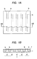
- FIGs. 1A and 1B An ink jet recording head according to a first reference example is shown in Figs. 1A and 1B and Figs. 2A and 2B.
- Figs. 1A and 1B in a fundamental construction of the ink jet recording head, five ink supply ports 5 are formed in a single substrate 1, and cyan ink is supplied to the ink supply ports 2A and 2E, magenta ink is supplied to the ink supply ports 2B and 2D and yellow ink is supplied to the ink supply port 2C.
- a discharge port plate 9 to be jointed to the substrate 1 is provided with large liquid droplet discharge ports 3a for discharging large liquid droplets and small liquid droplet discharge ports 3b for discharging small liquid droplets with respect to the respective ink supply ports 2.
- the large liquid droplet discharge ports 3a are disposed at a left side in Figs. 1A and 1B and small liquid droplet discharge ports 3b are disposed at a right side in Figs. 1A and 1B.
- the small liquid droplet discharge ports 3b are disposed at a left side in Figs. 1A and 1B and the large liquid droplet discharge ports 3a are disposed at a right side in Figs. 1A and 1B, and, regarding the ink supply port 2C, the large ink droplet discharge ports 3a are disposed on both sides.
- the substrate 1 is shifted in either direction along an arrangement direction of the ink supply ports 2 (left-and-right direction in Figs. 1A and 1B), the order for discharging the ink colors onto a recording medium (not shown) becomes the same, thereby preventing generation of color unevenness.
- the large liquid droplet discharge port 3a is provided at one side of each ink supply port 2 and the small liquid droplet discharge port 3b is provided at the other side.
- the discharge ports 3a and 3b are communicated with a common liquid chamber 6 via pressure chambers 4a and 4b and ink flow paths 5a and 5b, respectively, and the common liquid chamber 6 is communicated with the ink supply ports 2.
- Electro-thermal converting elements (referred to as “heaters” hereinafter) 7a and 7b are disposed within the pressure chambers 4a and 4b, respectively.
- nozzle a condition that the ink flow path is continued to the pressure chamber is generically referred to as "nozzle.”
- a cylindrical nozzle filter 8 integrally formed with the discharge port plate 9 is disposed in the vicinity of portions of the common liquid chamber 6 to which the ink flow paths 5a and 5b are connected.
- a length of the nozzle for the large liquid droplet is H L
- a length of the nozzle for the small liquid droplet is H S
- W L width of the nozzle for the small liquid droplet
- W S width of the nozzle for the small liquid droplet ink flow path 5b
- the flow resistances can be represented by the following equations:
- R f is resistance of the discharge port 3a or 3b alone. Relationship between flow resistances S Lb , S Sb and image quality Nozzle No. 1 2 3 4 5 Discharged Amount (pl) 5 2 2 2 2 2 Discharge Port Diameter ( ⁇ m) 16 10.5 10.5 10.5 10.5 10.5 Nozzle Filter Diameter ( ⁇ m) 10 10 10 15 Heater Size ( ⁇ m) 26 ⁇ 26 26 ⁇ 26 24 ⁇ 24 22 ⁇ 22 26 ⁇ 26 Flow Resistance S Lb , S Sb ( ⁇ m 2 ) 199 384 317 257 262 S Sb /S Lb Ratio 1 1.93 1.59 1.29 1.32 Image Quality ⁇ ⁇ ⁇ to ⁇ ⁇ ⁇
- the flow resistance S Sb of the nozzle No. 2 is greater than the flow resistance S Lb of the nozzle No. 1 by 1.93 times.
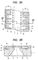
- H L H S and W L > W S are satisfied. Sizes of various parts including W S are sought by calculations similar to those in the first reference example.
- the flow resistances S Sb of the small liquid droplet ink flow paths 5b can be increased without increasing the dimension of the ink jet recording head.
- H L H S and W L > W S are satisfied, and, thus, the width of the small liquid droplet ink flow path 5b is smaller than the width of the small liquid droplet pressure chamber 4b. That is to say, although the large liquid droplet ink flow path 5a is directly connected to the large liquid droplet pressure chamber 4a with the same width, the small liquid droplet ink flow path 5b has the width smaller than that of the small liquid droplet pressure chamber 4b, and, thus, restriction for the ink flow is formed between the ink flow path and the pressure chamber.
- sizes of various parts are determined by calculations similar to those in the first reference example.
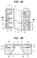
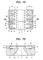
- the entire width of the small liquid droplet ink flow path 5b is small to make the configuration of the heater 4b narrower thereby to limit the size designing of the heater 4b, with the result that the driving designing and the designing of the resistance of the heater film are apt to be limited. Further, positional deviation of the nozzle in a short side direction of the heater 4b easily affects an influence upon the discharging direction. Further, there is a problem that, if the effective bubbling area is changed due to long term use, the change rate of the effective bubbling area becomes great. To the contrary, in the first embodiment, a degree of freedom of the designing of the size of the heater 4b is great and a degree of freedom of the driving designing and the designing of the heater film is great.
- the configuration of the heater can be selected as a square, the influence of the positional deviation of the nozzle affecting upon the discharge direction can be minimized, with the result that the change rate of the effective bubbling area during the long term use can be minimized.
- the other constructions are the similar to those in the first reference example.
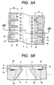
- a diameter of a nozzle filter 8b corresponding to the small liquid droplet ink flow path 5b is great.
- the other constructions are the same as those in the first embodiment. Sizes of various parts including the dimension of the nozzle filter 8b are sought by calculations similar to those in the first reference example.
- the flow resistance S Sb can be increased and optimized by making the nozzle filter 8b larger. Accordingly, there is little influence of manufacturing tolerance of the ink flow path 5b and dispersion in the flow resistances S Sb of the nozzles for the small liquid droplet is hard to be not so great. Further, since the width W S of the small liquid droplet ink flow path 5b is not so narrow and the nozzle filter 8b is large, dirt or debris is hard to be clogged.
- the small liquid droplet nozzles and the large liquid droplet nozzles are alternately disposed in the same column.
- the other constructions are the same as those in the first reference example.
- the distance between the large liquid droplet ink flow paths 5a and the distance between the small liquid droplet ink flow paths 5b can be widened, the cross-talk and influence of air flow between the large liquid droplet ink flow paths 5a or between the small liquid droplet ink flow paths 5b caused when high speed printing is performed by using only the large liquid droplets or the small liquid droplets can be reduced, thereby stabilizing the discharging and permitting high speed printing of a high quality image.
- the small liquid droplet nozzles and the large liquid droplet nozzles are alternately disposed in the same column.
- the other constructions are the same as those in the second reference example. Accordingly, similar to the third reference example, the cross-talk and the influence of the air flow caused when the high speed printing is performed by using only the large liquid droplets or small liquid droplets can be reduced, thereby stabilizing the discharging and permitting high speed printing of a high quality image. Further, similar to the second reference example, the flow resistances S Sb of the small liquid droplet ink flow paths 5b can be increased without increasing the size of the ink jet recording head.
- the small liquid droplet nozzles and the large liquid droplet nozzles are alternately disposed in the same column.
- the other constructions are the same as those in the first embodiment. Accordingly, similar to the first embodiment, the degree of freedom of designing of the size of the heater 4b is great, with the result that the influence of the positional deviation of the nozzle affecting upon the discharging direction can be minimized and the change rate of the effective bubbling area during the long term use can be minimized.
- the cross-talk and the influence of the air flow caused when the high speed printing is performed by using only the large liquid droplets or small liquid droplets can be reduced, thereby stabilizing the discharging and permitting high speed printing of a high quality image, and further, the flow resistances S Sb of the small liquid droplet ink flow paths 5b can be increased without increasing the size of the ink jet recording head.
- the small liquid droplet nozzles and the large liquid droplet nozzles are alternately disposed in the same column and the diameter of the nozzle filter 8b corresponding to the small liquid droplet ink flow path 65b is great.
- the other constructions are the same as those in the third embodiment. Accordingly, similar to the first embodiment, the degree of freedom of designing of the size of the heater 4b is great, with the result that the influence of the positional deviation of the nozzle affecting upon the discharging direction can be minimized and the change rate of the effective bubbling area during the long term use can be minimized.
- the cross-talk and the influence of the air flow caused when the high speed printing is performed by using only the large liquid droplets or small liquid droplets can be reduced, thereby stabilizing the discharging and permitting high speed printing of a high quality image, and further, the flow resistances S Sb of the small liquid droplet ink flow paths 5b can be increased without increasing the size of the ink jet recording head. Further, similar to the second embodiment, dispersion in the flow resistances S Sb of the nozzles for the small liquid droplet is hard to be great so much and thus the dirt is hard to be clogged.
- the width of the small liquid droplet ink flow path 5b is narrower than the width of the small liquid droplet pressure chamber 4b and the width of the large liquid droplet ink flow path 5a is narrower than the width of the large liquid droplet pressure chamber 4a so that both of the small liquid droplet ink flow path 5b and the large liquid droplet ink flow path 5a act as restriction portions for the ink flow.
- the width of the large liquid droplet pressure chamber is W RL
- the width of the large liquid droplet ink flow path is W L
- the width of the small liquid droplet pressure chamber is W RS
- the width of the small liquid droplet ink flow path is W S , W RL ⁇ W RS and W L > W S and W S /W RS ⁇ W L /W RL are satisfied.
- the other constructions are the same as those in the first embodiment. Accordingly, in not only the small liquid droplet ink flow paths 5b but also the large liquid droplet ink flow paths 5a, the flow resistances can be increased without increasing the size of the ink jet recording head.
- the degree of freedom of designing of the sizes of the heaters 4a and 4b is great, with the result that the influence of the positional deviation of the nozzle affecting upon the discharging direction can be minimized and the change rate of the effective bubbling area during the long term use can be minimized.
- the Inventors manufactured many nozzles and judged recording properties thereof. Among them, regarding the nozzles, which were able to achieve the good recording, heater sizes, pressure chamber volumes and pressure chamber widths are shown by Nos. 4 to 27. Further, Nos. 1 to 3 shows reference designing example when the heater size could be reduced.
- a common liquid chamber 6 is connected to discharge ports 3a and 3b via ink flow paths 5a and 5b and pressure chambers 4a and 4b, and ink droplets are discharged from the discharge ports 3a and 3b by utilizing thermal energy of heaters 7a and 7b.
- Widths of the ink flow paths 5a and 5b are narrower than widths of the pressure chambers 4a and 4b so that the ink flow paths 5a and 5b act as restriction portions.
- a sectional area of the small liquid droplet ink flow path is S S
- a sectional area of the small liquid droplet pressure chamber is S RS
- a sectional area of the large liquid droplet ink flow path is S L
- a sectional area of the large liquid droplet pressure chamber is S RL
Landscapes
- Physics & Mathematics (AREA)
- Geometry (AREA)
- Particle Formation And Scattering Control In Inkjet Printers (AREA)
- Ink Jet (AREA)
Applications Claiming Priority (2)
| Application Number | Priority Date | Filing Date | Title |
|---|---|---|---|
| JP2002121209A JP3927854B2 (ja) | 2002-04-23 | 2002-04-23 | インクジェット記録ヘッド |
| JP2002121209 | 2002-04-23 |
Publications (3)
| Publication Number | Publication Date |
|---|---|
| EP1356938A2 true EP1356938A2 (fr) | 2003-10-29 |
| EP1356938A3 EP1356938A3 (fr) | 2004-04-14 |
| EP1356938B1 EP1356938B1 (fr) | 2009-01-14 |
Family
ID=28786773
Family Applications (1)
| Application Number | Title | Priority Date | Filing Date |
|---|---|---|---|
| EP03009167A Expired - Lifetime EP1356938B1 (fr) | 2002-04-23 | 2003-04-22 | Tête d'impression jet d'encre |
Country Status (7)
| Country | Link |
|---|---|
| US (1) | US6830317B2 (fr) |
| EP (1) | EP1356938B1 (fr) |
| JP (1) | JP3927854B2 (fr) |
| KR (1) | KR100524570B1 (fr) |
| CN (1) | CN100515772C (fr) |
| DE (1) | DE60325798D1 (fr) |
| TW (1) | TWI225450B (fr) |
Cited By (6)
| Publication number | Priority date | Publication date | Assignee | Title |
|---|---|---|---|---|
| WO2006055643A3 (fr) * | 2004-11-18 | 2006-10-05 | Eastman Kodak Co | Configuration de reseau de buses de dispositif d'ejection de fluide |
| EP1619028A3 (fr) * | 2004-07-23 | 2007-08-01 | Samsung Electronics Co.,Ltd. | Tête à jet d'encre avec un membre de filtration intégré dans un substrate et méthode pour sa fabrication |
| WO2008013748A1 (fr) * | 2006-07-28 | 2008-01-31 | Hewlett-Packard Development Company, L.P. | Dispositifs d'éjection de fluide et procédés de fabrication |
| US7334878B2 (en) | 2004-09-08 | 2008-02-26 | Sony Corporation | Liquid ejection head and liquid ejection apparatus |
| US7690768B2 (en) * | 2006-02-02 | 2010-04-06 | Sony Corporation | Liquid ejecting head and liquid ejecting apparatus |
| EP3212420A4 (fr) * | 2014-10-30 | 2018-10-10 | Hewlett-Packard Development Company, L.P. | Impression a jet d'encre |
Families Citing this family (57)
| Publication number | Priority date | Publication date | Assignee | Title |
|---|---|---|---|---|
| JP4027281B2 (ja) * | 2002-07-10 | 2007-12-26 | キヤノン株式会社 | インクジェット記録ヘッド |
| JP3891561B2 (ja) | 2002-07-24 | 2007-03-14 | キヤノン株式会社 | インクジェット記録ヘッド |
| US20040040504A1 (en) * | 2002-08-01 | 2004-03-04 | Semiconductor Energy Laboratory Co., Ltd. | Manufacturing apparatus |
| JP4161881B2 (ja) * | 2003-11-13 | 2008-10-08 | ソニー株式会社 | 液体吐出方法 |
| US7249838B2 (en) * | 2004-01-21 | 2007-07-31 | Silverbrook Research Pty Ltd | Self threading wallpaper printer |
| JP4115465B2 (ja) * | 2004-06-02 | 2008-07-09 | キヤノン株式会社 | インクジェット記録ヘッド、インクジェット記録ヘッドを備えるインクジェットカートリッジ、及びインクジェット記録装置 |
| WO2009145759A1 (fr) * | 2008-05-25 | 2009-12-03 | Hewlett-Packard Development Company, L.P. | Dispositif de distribution précise de jet fluide comportant un ou plusieurs trous pour faire passer des bulles gazeuses, de la boue et/ou des contaminants durant l'amorçage |
| JP2006076011A (ja) * | 2004-09-07 | 2006-03-23 | Canon Inc | 液体噴射記録ヘッド |
| JP4574515B2 (ja) * | 2004-11-10 | 2010-11-04 | キヤノン株式会社 | 液体吐出ヘッド |
| JP4632421B2 (ja) | 2004-12-07 | 2011-02-16 | キヤノン株式会社 | インクジェット記録ヘッド |
| JP4845500B2 (ja) * | 2004-12-15 | 2011-12-28 | キヤノン株式会社 | データ生成装置 |
| JP4553360B2 (ja) * | 2004-12-24 | 2010-09-29 | キヤノン株式会社 | インクジェット記録ヘッド |
| JP4574385B2 (ja) * | 2005-02-17 | 2010-11-04 | キヤノン株式会社 | インクジェット記録ヘッドおよび記録装置 |
| JP4646665B2 (ja) * | 2005-03-28 | 2011-03-09 | キヤノン株式会社 | インクジェット記録ヘッド |
| JP4724490B2 (ja) * | 2005-08-09 | 2011-07-13 | キヤノン株式会社 | 液体吐出ヘッド |
| JP4768351B2 (ja) * | 2005-08-09 | 2011-09-07 | キヤノンファインテック株式会社 | インクジェット記録ヘッド及びそれを備えるインクジェット記録装置 |
| JP2007062272A (ja) * | 2005-09-01 | 2007-03-15 | Canon Inc | 液体吐出ヘッド |
| JP2007130852A (ja) * | 2005-11-09 | 2007-05-31 | Sony Corp | 液体吐出装置 |
| JP4298697B2 (ja) * | 2005-11-25 | 2009-07-22 | キヤノン株式会社 | インクジェット記録ヘッド、インクジェット記録ヘッドを備えるインクジェットカートリッジ、及びインクジェット記録装置 |
| JP4856982B2 (ja) * | 2006-03-02 | 2012-01-18 | キヤノン株式会社 | インクジェット記録ヘッド |
| EP2006111B1 (fr) * | 2006-03-29 | 2014-02-26 | Kyocera Corporation | Dispositif de distribution de liquide |
| US8037603B2 (en) * | 2006-04-27 | 2011-10-18 | Canon Kabushiki Kaisha | Ink jet head and producing method therefor |
| JP2008012688A (ja) * | 2006-07-03 | 2008-01-24 | Canon Inc | インクジェット記録ヘッド、インクジェット記録装置およびインクジェット記録ヘッドの製造方法 |
| JP2008018556A (ja) | 2006-07-11 | 2008-01-31 | Canon Inc | インクジェット記録ヘッド |
| US7832843B2 (en) * | 2006-08-28 | 2010-11-16 | Canon Kabushiki Kaisha | Liquid jet head |
| JP4933201B2 (ja) * | 2006-09-04 | 2012-05-16 | 富士フイルム株式会社 | 液体供給方法 |
| JP5037903B2 (ja) * | 2006-11-09 | 2012-10-03 | キヤノン株式会社 | インクジェット記録ヘッドおよびインクジェット記録装置 |
| US7926917B2 (en) * | 2006-12-06 | 2011-04-19 | Canon Kabushiki Kaisha. | Liquid recording head |
| JP2008149601A (ja) | 2006-12-19 | 2008-07-03 | Canon Inc | インクジェット記録方法 |
| US20080158304A1 (en) * | 2006-12-28 | 2008-07-03 | Toshiba Tec Kabushiki Kaisha | Ink-jet head |
| JP4953884B2 (ja) | 2007-03-30 | 2012-06-13 | キヤノン株式会社 | 記録ヘッド |
| JP5008443B2 (ja) * | 2007-04-11 | 2012-08-22 | キヤノン株式会社 | インクジェット記録ヘッドおよびインクジェット記録カートリッジ |
| US7984967B2 (en) * | 2007-04-13 | 2011-07-26 | Canon Kabushiki Kaisha | Ink jet head |
| JP2009006562A (ja) * | 2007-06-27 | 2009-01-15 | Canon Inc | インクジェット記録ヘッド |
| JP5058719B2 (ja) | 2007-08-30 | 2012-10-24 | キヤノン株式会社 | 液体吐出ヘッド及びインクジェット記録装置 |
| US7735962B2 (en) * | 2007-08-31 | 2010-06-15 | Canon Kabushiki Kaisha | Ink jet print head |
| JP5264123B2 (ja) * | 2007-08-31 | 2013-08-14 | キヤノン株式会社 | 液体吐出ヘッド |
| US8715918B2 (en) * | 2007-09-25 | 2014-05-06 | Az Electronic Materials Usa Corp. | Thick film resists |
| JP5031534B2 (ja) * | 2007-11-30 | 2012-09-19 | キヤノン株式会社 | インクジェット記録ヘッド |
| JP5183181B2 (ja) | 2007-12-11 | 2013-04-17 | キヤノン株式会社 | インクジェット記録ヘッド |
| JP5294884B2 (ja) * | 2008-02-08 | 2013-09-18 | キヤノン株式会社 | 液体吐出ヘッド |
| JP2010000649A (ja) | 2008-06-19 | 2010-01-07 | Canon Inc | 記録ヘッド |
| JP5317665B2 (ja) * | 2008-12-17 | 2013-10-16 | キヤノン株式会社 | 液体記録ヘッド |
| JP5202371B2 (ja) | 2009-02-06 | 2013-06-05 | キヤノン株式会社 | インクジェット記録ヘッド |
| JP5225132B2 (ja) | 2009-02-06 | 2013-07-03 | キヤノン株式会社 | 液体吐出ヘッドおよびインクジェット記録装置 |
| US8876242B2 (en) * | 2009-05-08 | 2014-11-04 | Canon Kabushiki Kaisha | Liquid ejection head |
| JP5787603B2 (ja) | 2011-04-28 | 2015-09-30 | キヤノン株式会社 | インクジェット記録ヘッドおよびインクジェット記録装置 |
| JP6150534B2 (ja) | 2013-01-25 | 2017-06-21 | キヤノン株式会社 | 半導体チップの製造方法 |
| JP6061088B2 (ja) * | 2013-03-28 | 2017-01-18 | セイコーエプソン株式会社 | 液体噴射ヘッド及び液体噴射装置 |
| WO2016068947A1 (fr) | 2014-10-30 | 2016-05-06 | Hewlett-Packard Development Company, L.P. | Tête d'impression à jet d'encre |
| CN107073955B (zh) | 2014-10-30 | 2018-10-12 | 惠普发展公司,有限责任合伙企业 | 喷墨打印头 |
| JP6422318B2 (ja) | 2014-12-02 | 2018-11-14 | キヤノン株式会社 | 液体吐出ヘッドおよび液体吐出ヘッドの製造方法 |
| WO2016175812A1 (fr) * | 2015-04-30 | 2016-11-03 | Hewlett-Packard Development Company, L.P. | Impression à poids de goutte double et simple |
| JP6532293B2 (ja) | 2015-05-22 | 2019-06-19 | キヤノン株式会社 | 液体吐出ヘッド、吐出素子基板および液体吐出装置 |
| JP6566770B2 (ja) | 2015-07-30 | 2019-08-28 | キヤノン株式会社 | 液体吐出ヘッドの制御方法および液体吐出装置 |
| WO2018029142A1 (fr) | 2016-08-09 | 2018-02-15 | AZ Electronic Materials (Luxembourg) S.à.r.l. | Réserve chimiquement amplifiée à film épais et stable sur le plan environnemental |
| US10875321B2 (en) | 2017-01-23 | 2020-12-29 | Hewlett-Packard Development Company, L.P. | Fluid ejection devices to dispense fluid of different sizes |
Family Cites Families (12)
| Publication number | Priority date | Publication date | Assignee | Title |
|---|---|---|---|---|
| US4746935A (en) * | 1985-11-22 | 1988-05-24 | Hewlett-Packard Company | Multitone ink jet printer and method of operation |
| US5208605A (en) * | 1991-10-03 | 1993-05-04 | Xerox Corporation | Multi-resolution roofshooter printheads |
| EP0594110B1 (fr) | 1992-10-20 | 2000-02-02 | Canon Kabushiki Kaisha | Tête d'impression par jet d'encre, sa méthode de fabrication et appareil à jet d'encre l'utilisant |
| US5412410A (en) * | 1993-01-04 | 1995-05-02 | Xerox Corporation | Ink jet printhead for continuous tone and text printing |
| ATE152399T1 (de) | 1993-02-26 | 1997-05-15 | Canon Kk | Tintenstrahldruckkopf, tintenstrahlkopf-kartusche und druckgerät |
| US5519423A (en) * | 1994-07-08 | 1996-05-21 | Hewlett-Packard Company | Tuned entrance fang configuration for ink-jet printers |
| EP0719647B1 (fr) | 1994-12-29 | 2005-12-14 | Canon Kabushiki Kaisha | Tête à jet d'encre avec plusiers éléments de chauffage par buse et imprimante l'utilisant |
| ES2203740T3 (es) | 1996-07-31 | 2004-04-16 | Canon Kabushiki Kaisha | Cabezal de chorros de burbujas y aparato para chorros de burbujas que utiliza el mismo. |
| US6042222A (en) * | 1997-08-27 | 2000-03-28 | Hewlett-Packard Company | Pinch point angle variation among multiple nozzle feed channels |
| DE60140411D1 (de) | 2000-09-06 | 2009-12-24 | Canon Kk | Tintenstrahlaufzeichnungskopf und Verfahren zu seiner Herstellung |
| JP2002178520A (ja) | 2000-10-02 | 2002-06-26 | Canon Inc | 液体吐出ヘッド、それを備えるヘッドカートリッジ、および液体吐出装置 |
| US6409318B1 (en) * | 2000-11-30 | 2002-06-25 | Hewlett-Packard Company | Firing chamber configuration in fluid ejection devices |
-
2002
- 2002-04-23 JP JP2002121209A patent/JP3927854B2/ja not_active Expired - Fee Related
-
2003
- 2003-04-16 TW TW092108831A patent/TWI225450B/zh not_active IP Right Cessation
- 2003-04-22 US US10/419,839 patent/US6830317B2/en not_active Expired - Lifetime
- 2003-04-22 KR KR20030025305A patent/KR100524570B1/ko not_active Expired - Fee Related
- 2003-04-22 EP EP03009167A patent/EP1356938B1/fr not_active Expired - Lifetime
- 2003-04-22 DE DE60325798T patent/DE60325798D1/de not_active Expired - Lifetime
- 2003-04-23 CN CNB031222439A patent/CN100515772C/zh not_active Expired - Fee Related
Cited By (11)
| Publication number | Priority date | Publication date | Assignee | Title |
|---|---|---|---|---|
| EP1619028A3 (fr) * | 2004-07-23 | 2007-08-01 | Samsung Electronics Co.,Ltd. | Tête à jet d'encre avec un membre de filtration intégré dans un substrate et méthode pour sa fabrication |
| US7334878B2 (en) | 2004-09-08 | 2008-02-26 | Sony Corporation | Liquid ejection head and liquid ejection apparatus |
| EP1634708A3 (fr) * | 2004-09-08 | 2009-01-14 | Sony Corporation | Tête d'éjection de liquide et dispositif d'éjection de liquide |
| WO2006055643A3 (fr) * | 2004-11-18 | 2006-10-05 | Eastman Kodak Co | Configuration de reseau de buses de dispositif d'ejection de fluide |
| US7350902B2 (en) | 2004-11-18 | 2008-04-01 | Eastman Kodak Company | Fluid ejection device nozzle array configuration |
| US7690768B2 (en) * | 2006-02-02 | 2010-04-06 | Sony Corporation | Liquid ejecting head and liquid ejecting apparatus |
| WO2008013748A1 (fr) * | 2006-07-28 | 2008-01-31 | Hewlett-Packard Development Company, L.P. | Dispositifs d'éjection de fluide et procédés de fabrication |
| US7909428B2 (en) | 2006-07-28 | 2011-03-22 | Hewlett-Packard Development Company, L.P. | Fluid ejection devices and methods of fabrication |
| EP3212420A4 (fr) * | 2014-10-30 | 2018-10-10 | Hewlett-Packard Development Company, L.P. | Impression a jet d'encre |
| US10661564B2 (en) | 2014-10-30 | 2020-05-26 | Hewlett-Packard Development Company, L.P. | Ink jet printing |
| US11331918B2 (en) | 2014-10-30 | 2022-05-17 | Hewlett-Packard Development Company, L.P. | Ink jet printing |
Also Published As
| Publication number | Publication date |
|---|---|
| JP3927854B2 (ja) | 2007-06-13 |
| KR100524570B1 (ko) | 2005-11-01 |
| DE60325798D1 (de) | 2009-03-05 |
| EP1356938B1 (fr) | 2009-01-14 |
| JP2003311964A (ja) | 2003-11-06 |
| TWI225450B (en) | 2004-12-21 |
| EP1356938A3 (fr) | 2004-04-14 |
| TW200401711A (en) | 2004-02-01 |
| CN100515772C (zh) | 2009-07-22 |
| US20030197760A1 (en) | 2003-10-23 |
| CN1453133A (zh) | 2003-11-05 |
| KR20030084654A (ko) | 2003-11-01 |
| US6830317B2 (en) | 2004-12-14 |
Similar Documents
| Publication | Publication Date | Title |
|---|---|---|
| US6830317B2 (en) | Ink jet recording head | |
| KR100977645B1 (ko) | 액체 토출 헤드 | |
| KR102179743B1 (ko) | 액체 토출용 기판, 액체 토출 헤드 및 액체 토출 장치 | |
| JP5362090B2 (ja) | 液体吐出ヘッド | |
| JP4323947B2 (ja) | インクジェット記録ヘッド | |
| US8177329B2 (en) | Ink jet print head | |
| JP5753739B2 (ja) | 液滴吐出ヘッド | |
| KR20020009081A (ko) | 버블 젯 방식의 잉크 젯 프린트 헤드 | |
| US7152951B2 (en) | High resolution ink jet printhead | |
| US8083325B2 (en) | Liquid ejection recording head having element substrate with plural supply ports | |
| US20070146451A1 (en) | Inkjet printhead | |
| KR100416544B1 (ko) | 이중히터를 가지는 버블젯 방식의 잉크젯프린트 헤드 | |
| JP4587157B2 (ja) | インクジェット記録ヘッドおよびインクジェット記録装置 | |
| US7334878B2 (en) | Liquid ejection head and liquid ejection apparatus | |
| US7465031B2 (en) | Liquid-ejection apparatus | |
| JP4137164B2 (ja) | インクジェット記録ヘッド | |
| US12350934B2 (en) | Liquid ejection head and liquid ejection apparatus | |
| KR100413680B1 (ko) | 버블 젯 방식의 잉크 젯 프린트 헤드 | |
| TWI277524B (en) | Print chip with an ink passage structure | |
| JP5531481B2 (ja) | 液体吐出ヘッド | |
| JP2004306334A (ja) | 液体吐出ヘッド |
Legal Events
| Date | Code | Title | Description |
|---|---|---|---|
| PUAI | Public reference made under article 153(3) epc to a published international application that has entered the european phase |
Free format text: ORIGINAL CODE: 0009012 |
|
| AK | Designated contracting states |
Kind code of ref document: A2 Designated state(s): AT BE BG CH CY CZ DE DK EE ES FI FR GB GR HU IE IT LI LU MC NL PT RO SE SI SK TR |
|
| AX | Request for extension of the european patent |
Extension state: AL LT LV MK |
|
| PUAL | Search report despatched |
Free format text: ORIGINAL CODE: 0009013 |
|
| AK | Designated contracting states |
Kind code of ref document: A3 Designated state(s): AT BE BG CH CY CZ DE DK EE ES FI FR GB GR HU IE IT LI LU MC NL PT RO SE SI SK TR |
|
| AX | Request for extension of the european patent |
Extension state: AL LT LV MK |
|
| 17P | Request for examination filed |
Effective date: 20040824 |
|
| AKX | Designation fees paid |
Designated state(s): DE FR GB IT |
|
| 17Q | First examination report despatched |
Effective date: 20060418 |
|
| GRAP | Despatch of communication of intention to grant a patent |
Free format text: ORIGINAL CODE: EPIDOSNIGR1 |
|
| GRAS | Grant fee paid |
Free format text: ORIGINAL CODE: EPIDOSNIGR3 |
|
| GRAA | (expected) grant |
Free format text: ORIGINAL CODE: 0009210 |
|
| AK | Designated contracting states |
Kind code of ref document: B1 Designated state(s): DE FR GB IT |
|
| REG | Reference to a national code |
Ref country code: GB Ref legal event code: FG4D |
|
| REF | Corresponds to: |
Ref document number: 60325798 Country of ref document: DE Date of ref document: 20090305 Kind code of ref document: P |
|
| PLBE | No opposition filed within time limit |
Free format text: ORIGINAL CODE: 0009261 |
|
| STAA | Information on the status of an ep patent application or granted ep patent |
Free format text: STATUS: NO OPPOSITION FILED WITHIN TIME LIMIT |
|
| 26N | No opposition filed |
Effective date: 20091015 |
|
| REG | Reference to a national code |
Ref country code: FR Ref legal event code: PLFP Year of fee payment: 14 |
|
| REG | Reference to a national code |
Ref country code: FR Ref legal event code: PLFP Year of fee payment: 15 |
|
| REG | Reference to a national code |
Ref country code: FR Ref legal event code: PLFP Year of fee payment: 16 |
|
| PGFP | Annual fee paid to national office [announced via postgrant information from national office to epo] |
Ref country code: IT Payment date: 20180420 Year of fee payment: 16 Ref country code: FR Payment date: 20180426 Year of fee payment: 16 |
|
| PGFP | Annual fee paid to national office [announced via postgrant information from national office to epo] |
Ref country code: GB Payment date: 20180427 Year of fee payment: 16 Ref country code: DE Payment date: 20180629 Year of fee payment: 16 |
|
| REG | Reference to a national code |
Ref country code: DE Ref legal event code: R119 Ref document number: 60325798 Country of ref document: DE |
|
| GBPC | Gb: european patent ceased through non-payment of renewal fee |
Effective date: 20190422 |
|
| PG25 | Lapsed in a contracting state [announced via postgrant information from national office to epo] |
Ref country code: DE Free format text: LAPSE BECAUSE OF NON-PAYMENT OF DUE FEES Effective date: 20191101 Ref country code: GB Free format text: LAPSE BECAUSE OF NON-PAYMENT OF DUE FEES Effective date: 20190422 |
|
| PG25 | Lapsed in a contracting state [announced via postgrant information from national office to epo] |
Ref country code: IT Free format text: LAPSE BECAUSE OF NON-PAYMENT OF DUE FEES Effective date: 20190422 |
|
| PG25 | Lapsed in a contracting state [announced via postgrant information from national office to epo] |
Ref country code: FR Free format text: LAPSE BECAUSE OF NON-PAYMENT OF DUE FEES Effective date: 20190430 |