EP1357413A2 - Leicht zugängliches Glasfaserkabel - Google Patents
Leicht zugängliches Glasfaserkabel Download PDFInfo
- Publication number
- EP1357413A2 EP1357413A2 EP03290594A EP03290594A EP1357413A2 EP 1357413 A2 EP1357413 A2 EP 1357413A2 EP 03290594 A EP03290594 A EP 03290594A EP 03290594 A EP03290594 A EP 03290594A EP 1357413 A2 EP1357413 A2 EP 1357413A2
- Authority
- EP
- European Patent Office
- Prior art keywords
- tube
- zones
- element according
- cable element
- grooves
- Prior art date
- Legal status (The legal status is an assumption and is not a legal conclusion. Google has not performed a legal analysis and makes no representation as to the accuracy of the status listed.)
- Withdrawn
Links
- 230000003287 optical effect Effects 0.000 title claims abstract description 28
- 230000005540 biological transmission Effects 0.000 claims abstract description 4
- 239000000463 material Substances 0.000 claims description 21
- 230000001681 protective effect Effects 0.000 claims description 15
- 238000000034 method Methods 0.000 claims description 5
- 238000005452 bending Methods 0.000 claims description 4
- 239000013307 optical fiber Substances 0.000 description 3
- 239000004800 polyvinyl chloride Substances 0.000 description 3
- 239000004698 Polyethylene Substances 0.000 description 2
- 238000009795 derivation Methods 0.000 description 2
- 239000000835 fiber Substances 0.000 description 2
- -1 polyethylene Polymers 0.000 description 2
- 229920000573 polyethylene Polymers 0.000 description 2
- 229920000915 polyvinyl chloride Polymers 0.000 description 2
- 239000004760 aramid Substances 0.000 description 1
- 229920003235 aromatic polyamide Polymers 0.000 description 1
- 230000015572 biosynthetic process Effects 0.000 description 1
- 239000000470 constituent Substances 0.000 description 1
- 238000010586 diagram Methods 0.000 description 1
- 230000000694 effects Effects 0.000 description 1
- 230000006355 external stress Effects 0.000 description 1
- 238000001125 extrusion Methods 0.000 description 1
- 238000005188 flotation Methods 0.000 description 1
- 239000003365 glass fiber Substances 0.000 description 1
- 230000001012 protector Effects 0.000 description 1
- 238000007789 sealing Methods 0.000 description 1
- 230000035939 shock Effects 0.000 description 1
- 239000007779 soft material Substances 0.000 description 1
- 230000035882 stress Effects 0.000 description 1
Images
Classifications
-
- H—ELECTRICITY
- H01—ELECTRIC ELEMENTS
- H01B—CABLES; CONDUCTORS; INSULATORS; SELECTION OF MATERIALS FOR THEIR CONDUCTIVE, INSULATING OR DIELECTRIC PROPERTIES
- H01B7/00—Insulated conductors or cables characterised by their form
- H01B7/38—Insulated conductors or cables characterised by their form with arrangements for facilitating removal of insulation
-
- G—PHYSICS
- G02—OPTICS
- G02B—OPTICAL ELEMENTS, SYSTEMS OR APPARATUS
- G02B6/00—Light guides; Structural details of arrangements comprising light guides and other optical elements, e.g. couplings
- G02B6/44—Mechanical structures for providing tensile strength and external protection for fibres, e.g. optical transmission cables
- G02B6/4401—Optical cables
- G02B6/4429—Means specially adapted for strengthening or protecting the cables
- G02B6/443—Protective covering
- G02B6/4431—Protective covering with provision in the protective covering, e.g. weak line, for gaining access to one or more fibres, e.g. for branching or tapping
Definitions
- the invention relates to the field of optical cables.
- Optical cables generally include at least one outer sheath surrounding at least one protective tube in which optical transmission elements (possibly fibers gathered in ribbons or in modules or in more rigid tubes small diameter).
- optical elements contained in these cables It must of course be possible to access the optical elements contained in these cables.
- certain optical elements When these cables are installed in telecommunication networks, certain optical elements must be isolated for connection to other optical elements in order to make derivations. Optical elements must also be available to operators to enable them to search for anomalies.
- the sheaths outside of the cable and the protection tube must be open. In this Indeed, operators use cutting tools to incise different sheaths.
- the incision of the protective tube is the most delicate operation and it is necessary to use a specific tool not to risk to damage optical elements contained in the tube.
- optical cable structures to avoid the use of such tools to limit the risk of damage to optical elements.
- document EP 1 006 384 published on June 07, 2000 describes an optical cable in which the protective tube is made of a translucent and flexible material of the polyethylene type of medium density.
- the tube has longitudinal areas of least resistance. Because of the translucency of the material, the operator easily visualizes the areas longitudinal. In this type of cable, the operator pinches and pulls out a portion of polyethylene strip formed between the longitudinal zones.
- a general object of the invention is to provide an optical cable in which opening of the protective tube can be done without tools specific.
- the invention proposes an optical cable element comprising a cylindrical protection tube, the protective tube in which extend optical transmission elements, characterized in that the protection tube has at least two areas of less mechanical resistance which extend at least in part in its length, one of these areas having a lower resistance than the other.
- This characteristic creates an asymmetry of the section of the tube which has the effect, when the tube is subjected to torsion, to drive first the rupture of the tube in its thickness at the level of the longitudinal zone less resistant.
- the most resistant longitudinal zone then constitutes a hinge allowing tilting, the release of a portion of the tube.
- the tubes used in the invention may consist of a translucent material or not, reinforced or not.
- the protective tube includes at least two areas of reduced thickness, one of the areas having a greater material thickness than the other zone.
- the protection tube may have at least two grooves longitudinal, one of said grooves being deeper than the other.
- These grooves are areas of least resistance that cause the tube to rupture in its thickness when it is subjected to a twist.
- the grooves are formed on the inner surface of the protective tube, one of the grooves being deeper than the other.
- the protection tube can also have on its surface outer longitudinal grooves, each of said grooves external longitudinal lines being positioned opposite an internal groove relative to the thickness of the wall of the protection tube.
- External grooves advantageously allow an operator to easily locate the position of the internal grooves.
- external grooves also makes it possible to control the thickness of material between an internal groove and the outer groove positioned opposite.
- the invention also proposes a method for locally opening a optical cable comprising an element as previously defined, characterized in that at least one twist is applied to the tube which causes the local rupture of the tube in the weakest zone, followed by a bending which causes the opening of the tube and the release of a portion of tube located between the two zones of least resistance, and one draws the portion tube thus released to cause local rupture of the tube at the level another zone of lesser resistance.
- This process is particularly simple and does not require the use of cutting tool when opening the protection tube. he can so be repeated at regular intervals along the cable when desired perform a series of derivations.
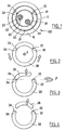
- the optical cable 100 comprises an outer sheath Surrounding a protective tube 20 enclosing optical modules 42 and 44.
- Each optical module 42 and 44 is comprised of a fiber bundle 40 surrounded by an envelope.
- the optical modules 42 and 44 are surrounded by a sealing envelope constituted by example of a hydro-flotation ribbon.
- Optical cable also includes a layer 12 of carrier elements positioned between the outer sheath 10 and the protection tube 20. These carrying elements are intended to support the tensile stresses in the cable 100, they are formed for example aramid or glass fibers added to the tube 20.
- the protective tube 20 is made of polyvinyl chloride (PVC) or polyvinyl chloride superchlorinated (PVC-C). It has an outside diameter of about 9 mm and a inner diameter of about 6.6 mm.
- This tube 20 comprises on its surface 23 internal two longitudinal grooves 32 and 34 having a section V. The groove 32 is deeper than the groove 34.
- the protective tube 20 further comprises on its surface outer 21 two identical external grooves 22 and 24 identical longitudinal between them and having a rounded section. Each external groove 22, 24 is located respectively facing an internal groove 32, 34 by relative to the wall of the tube 20.
- each pair 22, 32 and 24, 34 of internal and external grooves positioned opposite one another and on both sides of the wall of the tube 20 creates in the length of this tube an area of reduced thickness.
- the thickness of material between the grooves 22 and 32 and 24 and 34 is preferably between 0.1 and 0.5 mm, the thickness of material between the grooves 24 and 34 being more important that the thickness of material between the grooves 22 and 32. This thickness of material depends of course on the thickness of the tube 20. It will be even more important that the thickness of the tube 20 is important. In the case of the exemplary PVC tube, the material thickness between the grooves 22 and 32 is approximately 0.2 mm and the thickness of material between the grooves 24 and 34 is about 0.3 mm.
- Each area of reduced thickness constitutes a zone of least resistance to open the tube without the help of a specific tool.
- FIG. 2 represents a first step of opening the tube of 20.
- the operator applies to the tube 20 a twist around the central axis X of the tube 20 (indicated by arrows) at the location of the cable where he wants to access the optical fibers. This twist causes the rupture of the material thickness between the outer groove 32 and the internal groove 22.
- FIG. 3 represents a second step of opening the tube of 20.
- the tube 20 has been torn at the level of grooves 32 and 22.
- the operator then applies to the tube 20 a flexion (indicated by an arrow) substantially in the plane P of the internal grooves 22 and 24, the concavity of the flexion being directed towards the groove 24 the least deep.
- This bending causes the release of a portion 28 of tube 20 located between the two areas of least resistance.
- a third step the operator pulls on the tube portion 28 unobstructed, which then causes the rupture of the material thickness between the outer groove 34 and the inner groove 24.
- FIG. 4 represents the tube 20 when it has been torn at the level of two internal grooves 22 and 24.
- the operator raises and pulls the portion of tube 28 located between the two grooves 22 and 24 and thus propagates the rupture grooves along the tube 20 over the desired distance.
- the spread of the break forms a strip of material that can then be cut for be detached from the tube 20.
- the grooves 22 and 24 are not diametrically opposed. They are spaced far enough apart to create a band of detachable material 28 for access to the optical fibers.
- grooves 22 and 24 are positioned forming an angle between them between 90 and 150 degrees, preferably 120 degrees.
- the grooves allow the operator to visualize the location of the grooves internal.
- the tube may also comprise on its outer wall indications or a location to locate the area of least resistance with the highest resistance and the area of least resistance with the lowest resistance.
- Marking lines can be made on the outer wall of the tube using any appropriate marking technique. These lines of marking may for example be made in the form of reliefs positioned on either side of one of the outer grooves. These markings are advantageously made during the extrusion of the tube. The operator can thus distinguish the zone of least resistance the most important tearing resistance of the zone of least resistance with the lowest tear resistance. This This characteristic allows the operator to deduce the meaning in which to be carried out the bending to cause the release of the portion of tube located between the two areas of least resistance.
Landscapes
- Physics & Mathematics (AREA)
- General Physics & Mathematics (AREA)
- Optics & Photonics (AREA)
- Light Guides In General And Applications Therefor (AREA)
- Mechanical Coupling Of Light Guides (AREA)
Applications Claiming Priority (2)
| Application Number | Priority Date | Filing Date | Title |
|---|---|---|---|
| FR0203088A FR2837286B1 (fr) | 2002-03-12 | 2002-03-12 | Cable optique a accessibilite |
| FR0203088 | 2002-03-12 |
Publications (2)
| Publication Number | Publication Date |
|---|---|
| EP1357413A2 true EP1357413A2 (de) | 2003-10-29 |
| EP1357413A3 EP1357413A3 (de) | 2004-02-04 |
Family
ID=27772065
Family Applications (1)
| Application Number | Title | Priority Date | Filing Date |
|---|---|---|---|
| EP03290594A Withdrawn EP1357413A3 (de) | 2002-03-12 | 2003-03-11 | Leicht zugängliches Glasfaserkabel |
Country Status (2)
| Country | Link |
|---|---|
| EP (1) | EP1357413A3 (de) |
| FR (1) | FR2837286B1 (de) |
Families Citing this family (3)
| Publication number | Priority date | Publication date | Assignee | Title |
|---|---|---|---|---|
| DE102004015957A1 (de) * | 2004-03-31 | 2005-10-27 | CCS Technology, Inc., Wilmington | Mechanisch auftrennbares Kabel |
| EP2587291A1 (de) * | 2011-10-28 | 2013-05-01 | Alcatel Lucent | Kabel und Verfahren zur Herstellung eines Kabels |
| EP3629432A1 (de) * | 2018-09-25 | 2020-04-01 | Nokia Shanghai Bell Co., Ltd. | Vorrichtung, verfahren und system zur elektrischen verbindung |
Family Cites Families (8)
| Publication number | Priority date | Publication date | Assignee | Title |
|---|---|---|---|---|
| GB8520906D0 (en) * | 1985-08-21 | 1985-09-25 | Telephone Cables Ltd | Optical fibre cables |
| JPS6249310A (ja) * | 1985-08-29 | 1987-03-04 | Nippon Telegr & Teleph Corp <Ntt> | 光フアイバチユ−ブユニツト |
| DE3922475A1 (de) * | 1989-07-06 | 1991-01-17 | Siemens Ag | Optisches nachrichtenkabel |
| JP2957267B2 (ja) * | 1990-11-27 | 1999-10-04 | 住友電気工業株式会社 | 光フアイバ心線 |
| US5067830A (en) * | 1990-12-21 | 1991-11-26 | Siecor Corporation | Indented tube for optical ribbon |
| US5668912A (en) * | 1996-02-07 | 1997-09-16 | Alcatel Na Cable Systems, Inc. | Rectangular optical fiber cable |
| US6134363A (en) * | 1999-02-18 | 2000-10-17 | Alcatel | Method for accessing optical fibers in the midspan region of an optical fiber cable |
| FR2810747B1 (fr) * | 2000-06-23 | 2002-12-20 | Acome Soc Coop Travailleurs | Cable optique a accessibilite continue |
-
2002
- 2002-03-12 FR FR0203088A patent/FR2837286B1/fr not_active Expired - Fee Related
-
2003
- 2003-03-11 EP EP03290594A patent/EP1357413A3/de not_active Withdrawn
Also Published As
| Publication number | Publication date |
|---|---|
| FR2837286A1 (fr) | 2003-09-19 |
| EP1357413A3 (de) | 2004-02-04 |
| FR2837286B1 (fr) | 2004-06-11 |
Similar Documents
| Publication | Publication Date | Title |
|---|---|---|
| EP0864896B1 (de) | Optische Einheit für ein Faseroptischeskabel | |
| CN104040400B (zh) | 具有铠装件、缓冲管及护套接入特征结构的铠装电缆 | |
| EP0846971B1 (de) | Verstärktes faseroptisches Kabel mit einer Einrohrstruktur | |
| EP0011561B1 (de) | Verfahren zum Anbringen einer optischen Faser in einer Verbindungszwinge | |
| FR2503385A1 (fr) | Procede de fabrication de cable de fibres optiques et cable ainsi obtenu | |
| EP1588201A1 (de) | Faseroptisches kabel mit haltemantel | |
| EP0720034A1 (de) | Optisches Kabel und Verfahren zu seiner Fabrikation | |
| EP0365062A1 (de) | Faseroptischer Drucksensor | |
| FR2793565A1 (fr) | Cable a fibres optiques ayant des renforts longitudinaux reperes | |
| EP1357413A2 (de) | Leicht zugängliches Glasfaserkabel | |
| FR2762101A1 (fr) | Protection d'epissure et dispositif de reception de guides d'ondes lumineuses ainsi que dispositif pour inserer les guides d'ondes lumineuses dans la protection d'epissure | |
| EP1972977A1 (de) | Optisches Kabel zum Anschluss an ein allgemeines Verteilernetz und Anschlussverfahren dieses Kabels | |
| EP0062345A1 (de) | Verfahren zur Verbindung fiberoptischer Unterseekabel | |
| FR2662270A1 (fr) | Dispositif et procede d'epanouissement de fibres optiques au-dela d'une extremite gainee de cable. | |
| EP2416194A1 (de) | Durchführung für ein optisches Faserband | |
| FR2714977A1 (fr) | Câble optique et son procédé de fabrication. | |
| EP3729156A1 (de) | Optisches kabel mit ripcords | |
| FR2745393A1 (fr) | Dispositif de support d'epissures, notamment pour fibres ou modules optiques | |
| WO2015136007A1 (fr) | Dispositif pour la surveillance d'une structure a l'aide de cables optiques et procede de raccordement de cables optiques associe | |
| EP4057041A1 (de) | Optisches kabel zum installieren in eine ummantelung durch verlegung mithilfe eines fluids | |
| EP4083673B1 (de) | Kabelanordnung mit routingfähigen spleissschutzvorrichtungen | |
| FR2476856A1 (fr) | Dispositif de connexion de fibres optiques et procede pour sa mise en oeuvre | |
| FR2740229A1 (fr) | Outil de denudage pour ruban de fibres optiques | |
| FR2759503A1 (fr) | Organe de fermeture de raccord de cable | |
| EP1351084A1 (de) | Glasfaserkabel und sein Herstellungsprozess |
Legal Events
| Date | Code | Title | Description |
|---|---|---|---|
| PUAI | Public reference made under article 153(3) epc to a published international application that has entered the european phase |
Free format text: ORIGINAL CODE: 0009012 |
|
| AK | Designated contracting states |
Kind code of ref document: A2 Designated state(s): AT BE BG CH CY CZ DE DK EE ES FI FR GB GR HU IE IT LI LU MC NL PT RO SE SI SK TR |
|
| AX | Request for extension of the european patent |
Extension state: AL LT LV MK |
|
| PUAL | Search report despatched |
Free format text: ORIGINAL CODE: 0009013 |
|
| AK | Designated contracting states |
Kind code of ref document: A3 Designated state(s): AT BE BG CH CY CZ DE DK EE ES FI FR GB GR HU IE IT LI LU MC NL PT RO SE SI SK TR |
|
| AX | Request for extension of the european patent |
Extension state: AL LT LV MK |
|
| AKX | Designation fees paid | ||
| REG | Reference to a national code |
Ref country code: DE Ref legal event code: 8566 |
|
| STAA | Information on the status of an ep patent application or granted ep patent |
Free format text: STATUS: THE APPLICATION IS DEEMED TO BE WITHDRAWN |
|
| 18D | Application deemed to be withdrawn |
Effective date: 20040805 |