EP1357613A2 - Effiziente Leuchtdiode - Google Patents
Effiziente Leuchtdiode Download PDFInfo
- Publication number
- EP1357613A2 EP1357613A2 EP03076076A EP03076076A EP1357613A2 EP 1357613 A2 EP1357613 A2 EP 1357613A2 EP 03076076 A EP03076076 A EP 03076076A EP 03076076 A EP03076076 A EP 03076076A EP 1357613 A2 EP1357613 A2 EP 1357613A2
- Authority
- EP
- European Patent Office
- Prior art keywords
- compound
- host
- light emitting
- layer
- emitting layer
- Prior art date
- Legal status (The legal status is an assumption and is not a legal conclusion. Google has not performed a legal analysis and makes no representation as to the accuracy of the status listed.)
- Withdrawn
Links
- TVSXRWNJJYLPGI-UHFFFAOYSA-N CN(c1cc(F)ccc11)c(cc(c(N(C)c2c3ccc(F)c2)c2)C3=O)c2C1=O Chemical compound CN(c1cc(F)ccc11)c(cc(c(N(C)c2c3ccc(F)c2)c2)C3=O)c2C1=O TVSXRWNJJYLPGI-UHFFFAOYSA-N 0.000 description 1
- RGKUJDPPZJQSJC-UHFFFAOYSA-N c(cc1)ccc1-[n](c1c2cccc1)c(-c1ccc3-4)c2-c(cc2)c1c3c2-c1cccc2c1c-4ccc2 Chemical compound c(cc1)ccc1-[n](c1c2cccc1)c(-c1ccc3-4)c2-c(cc2)c1c3c2-c1cccc2c1c-4ccc2 RGKUJDPPZJQSJC-UHFFFAOYSA-N 0.000 description 1
Images
Classifications
-
- H—ELECTRICITY
- H10—SEMICONDUCTOR DEVICES; ELECTRIC SOLID-STATE DEVICES NOT OTHERWISE PROVIDED FOR
- H10K—ORGANIC ELECTRIC SOLID-STATE DEVICES
- H10K85/00—Organic materials used in the body or electrodes of devices covered by this subclass
- H10K85/60—Organic compounds having low molecular weight
- H10K85/615—Polycyclic condensed aromatic hydrocarbons, e.g. anthracene
- H10K85/624—Polycyclic condensed aromatic hydrocarbons, e.g. anthracene containing six or more rings
-
- H—ELECTRICITY
- H10—SEMICONDUCTOR DEVICES; ELECTRIC SOLID-STATE DEVICES NOT OTHERWISE PROVIDED FOR
- H10K—ORGANIC ELECTRIC SOLID-STATE DEVICES
- H10K85/00—Organic materials used in the body or electrodes of devices covered by this subclass
- H10K85/60—Organic compounds having low molecular weight
- H10K85/649—Aromatic compounds comprising a hetero atom
- H10K85/657—Polycyclic condensed heteroaromatic hydrocarbons
-
- H—ELECTRICITY
- H10—SEMICONDUCTOR DEVICES; ELECTRIC SOLID-STATE DEVICES NOT OTHERWISE PROVIDED FOR
- H10K—ORGANIC ELECTRIC SOLID-STATE DEVICES
- H10K50/00—Organic light-emitting devices
- H10K50/10—OLEDs or polymer light-emitting diodes [PLED]
- H10K50/11—OLEDs or polymer light-emitting diodes [PLED] characterised by the electroluminescent [EL] layers
-
- H—ELECTRICITY
- H10—SEMICONDUCTOR DEVICES; ELECTRIC SOLID-STATE DEVICES NOT OTHERWISE PROVIDED FOR
- H10K—ORGANIC ELECTRIC SOLID-STATE DEVICES
- H10K50/00—Organic light-emitting devices
- H10K50/10—OLEDs or polymer light-emitting diodes [PLED]
- H10K50/18—Carrier blocking layers
-
- H—ELECTRICITY
- H10—SEMICONDUCTOR DEVICES; ELECTRIC SOLID-STATE DEVICES NOT OTHERWISE PROVIDED FOR
- H10K—ORGANIC ELECTRIC SOLID-STATE DEVICES
- H10K85/00—Organic materials used in the body or electrodes of devices covered by this subclass
- H10K85/30—Coordination compounds
- H10K85/341—Transition metal complexes, e.g. Ru(II)polypyridine complexes
- H10K85/342—Transition metal complexes, e.g. Ru(II)polypyridine complexes comprising iridium
-
- H—ELECTRICITY
- H10—SEMICONDUCTOR DEVICES; ELECTRIC SOLID-STATE DEVICES NOT OTHERWISE PROVIDED FOR
- H10K—ORGANIC ELECTRIC SOLID-STATE DEVICES
- H10K85/00—Organic materials used in the body or electrodes of devices covered by this subclass
- H10K85/30—Coordination compounds
- H10K85/341—Transition metal complexes, e.g. Ru(II)polypyridine complexes
- H10K85/346—Transition metal complexes, e.g. Ru(II)polypyridine complexes comprising platinum
-
- H—ELECTRICITY
- H10—SEMICONDUCTOR DEVICES; ELECTRIC SOLID-STATE DEVICES NOT OTHERWISE PROVIDED FOR
- H10K—ORGANIC ELECTRIC SOLID-STATE DEVICES
- H10K85/00—Organic materials used in the body or electrodes of devices covered by this subclass
- H10K85/30—Coordination compounds
- H10K85/351—Metal complexes comprising lanthanides or actinides, e.g. comprising europium
-
- H—ELECTRICITY
- H10—SEMICONDUCTOR DEVICES; ELECTRIC SOLID-STATE DEVICES NOT OTHERWISE PROVIDED FOR
- H10K—ORGANIC ELECTRIC SOLID-STATE DEVICES
- H10K85/00—Organic materials used in the body or electrodes of devices covered by this subclass
- H10K85/60—Organic compounds having low molecular weight
- H10K85/615—Polycyclic condensed aromatic hydrocarbons, e.g. anthracene
- H10K85/622—Polycyclic condensed aromatic hydrocarbons, e.g. anthracene containing four rings, e.g. pyrene
-
- H—ELECTRICITY
- H10—SEMICONDUCTOR DEVICES; ELECTRIC SOLID-STATE DEVICES NOT OTHERWISE PROVIDED FOR
- H10K—ORGANIC ELECTRIC SOLID-STATE DEVICES
- H10K85/00—Organic materials used in the body or electrodes of devices covered by this subclass
- H10K85/60—Organic compounds having low molecular weight
- H10K85/615—Polycyclic condensed aromatic hydrocarbons, e.g. anthracene
- H10K85/623—Polycyclic condensed aromatic hydrocarbons, e.g. anthracene containing five rings, e.g. pentacene
-
- H—ELECTRICITY
- H10—SEMICONDUCTOR DEVICES; ELECTRIC SOLID-STATE DEVICES NOT OTHERWISE PROVIDED FOR
- H10K—ORGANIC ELECTRIC SOLID-STATE DEVICES
- H10K85/00—Organic materials used in the body or electrodes of devices covered by this subclass
- H10K85/60—Organic compounds having low molecular weight
- H10K85/615—Polycyclic condensed aromatic hydrocarbons, e.g. anthracene
- H10K85/626—Polycyclic condensed aromatic hydrocarbons, e.g. anthracene containing more than one polycyclic condensed aromatic rings, e.g. bis-anthracene
-
- H—ELECTRICITY
- H10—SEMICONDUCTOR DEVICES; ELECTRIC SOLID-STATE DEVICES NOT OTHERWISE PROVIDED FOR
- H10K—ORGANIC ELECTRIC SOLID-STATE DEVICES
- H10K85/00—Organic materials used in the body or electrodes of devices covered by this subclass
- H10K85/60—Organic compounds having low molecular weight
- H10K85/631—Amine compounds having at least two aryl rest on at least one amine-nitrogen atom, e.g. triphenylamine
-
- H—ELECTRICITY
- H10—SEMICONDUCTOR DEVICES; ELECTRIC SOLID-STATE DEVICES NOT OTHERWISE PROVIDED FOR
- H10K—ORGANIC ELECTRIC SOLID-STATE DEVICES
- H10K85/00—Organic materials used in the body or electrodes of devices covered by this subclass
- H10K85/60—Organic compounds having low molecular weight
- H10K85/649—Aromatic compounds comprising a hetero atom
- H10K85/656—Aromatic compounds comprising a hetero atom comprising two or more different heteroatoms per ring
-
- Y—GENERAL TAGGING OF NEW TECHNOLOGICAL DEVELOPMENTS; GENERAL TAGGING OF CROSS-SECTIONAL TECHNOLOGIES SPANNING OVER SEVERAL SECTIONS OF THE IPC; TECHNICAL SUBJECTS COVERED BY FORMER USPC CROSS-REFERENCE ART COLLECTIONS [XRACs] AND DIGESTS
- Y10—TECHNICAL SUBJECTS COVERED BY FORMER USPC
- Y10S—TECHNICAL SUBJECTS COVERED BY FORMER USPC CROSS-REFERENCE ART COLLECTIONS [XRACs] AND DIGESTS
- Y10S428/00—Stock material or miscellaneous articles
- Y10S428/917—Electroluminescent
Definitions
- This invention relates to an organic light emitting diode (OLED) electroluminescent (EL) device comprising a light-emitting layer containing an indeno[1,2,3- cd ]perylene compound.
- OLED organic light emitting diode
- EL electroluminescent
- an organic EL device is comprised of an anode for hole injection, a cathode for electron injection, and an organic medium sandwiched between these electrodes to support charge recombination that yields emission of light. These devices are also commonly referred to as organic light-emitting diodes, or OLEDs.
- organic EL devices are Gurnee et al. U.S. Pat. No. 3,172,862, issued Mar. 9, 1965; Gurnee U.S. Pat. No. 3,173,050, issued Mar.
- More recent organic EL devices include an organic EL element consisting of extremely thin layers (e.g. ⁇ 1.0 ⁇ m ) between the anode and the cathode.
- the organic EL element encompasses the layers between the anode and cathode electrodes. Reducing the thickness lowered the resistance of the organic layer and has enabled devices that operate at much lower voltage.
- one organic layer of the EL element adjacent to the anode is specifically chosen to transport holes, therefore, it is referred to as the hole-transporting layer, and the other organic layer is specifically chosen to transport electrons, referred to as the electron-transporting layer.
- the interface between the two layers provides an efficient site for the recombination of the injected hole/electron pair and the resultant electroluminescence.
- the light-emitting layer commonly consists of a host material doped with a guest material - dopant , which results in an efficiency improvement and allows color tuning.
- organic EL device components such as dopants
- a useful class of dopants is derived from the quinacridone compounds and disclosed in US 5,593,788. These materials are characterized by a broad emission envelope and a high luminance quantum yield. However, the stability of these materials in an OLED is insufficient for a broad range of OLED applications.
- Another useful class of dopants is the indenoperylene class of materials as disclosed in EP 1 148 109 A2. These materials are characterized by a "perylene-type" emission spectrum in the green region of the spectrum. It is reported in this work that materials of this class provide unexpected and exceptional device stability when used as a dopant in anthracene and oxinoid hosts as a dopant.
- the invention provides an OLED device comprising an anode, a hole transporting layer (HTL), a green light emitting layer (LEL), an electron transporting layer (ETL) and a cathode wherein the light emitting layer comprises a host and up to 10 wt% of a green light emitting indeno[1,2,3- cd ]perylene dopant compound.
- HTL hole transporting layer
- LEL green light emitting layer
- ETL electron transporting layer
- cathode wherein the light emitting layer comprises a host and up to 10 wt% of a green light emitting indeno[1,2,3- cd ]perylene dopant compound.
- Devices of the invention provide improved luminance efficiency.
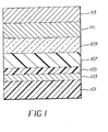
- FIG. 1 shows a cross-section of a typical OLED device in which this invention may be used.
- the invention is as summarized above.
- An OLED device of the invention is a multilayer electroluminescent device comprising a cathode, an anode, charge-injecting layers (if necessary), charge-transporting layers, and a light-emitting layer (LEL) comprising a host and at least one dopant, an indeno[1,2,3- cd ]perylene.
- LEL light-emitting layer
- indenoperylene refers to a perylene core with an indene fusion between the 1,2,3 positions of indene and cd faces of perylene.
- indenoperylene is also used to more generally describe materials wherein the fusion between indene's 1,2,3 positions and perylene's cd faces is not limited solely to indene as defined by the above reference.
- indene can also include analogous materials wherein the benzo-group of indene can be a ring of 5, 6, or 7 atoms comprising carbon or heteroatoms such as nitrogen, sulfur or oxygen.
- the light-emitting layer of the device comprises a host and an emitting dopant where the dopant is present in an amount of up to 10 wt % of the host, more typically from 0.1-2.0 wt % of the host.
- the host functions as an initial "energy capture agent" that transfers that energy to the dopant or guest material as the primary light emitter.
- the host is present in the light emitting layer in an amount of at least 40 wt%.
- Desirable hosts include those based on a chelated oxinoid compound, a benzazole or an anthracene compound although they are not limited to these three classes of host.
- Particular examples of hosts are tris(8-quinolinolato)aluminum (III), 2,2',2"-(1,3,5-benzenetriyl)tris[1-phenyl-lH-benzimidazole] and 2- tert -butyl-9,10-di-(2-naphthyl)anthracene.
- Embodiments of the dopants useful in the invention provide an emitted light having a green hue. Substituents are selected to provide embodiments that exhibit a reduced loss of initial luminance compared to the device containing no indenoperylene of claim 1.
- a useful and convenient embodiment is where R1-10 are all hydrogen and A is a six membered aromatic hydrocarbon ring and two substituents Y are phenyl groups and two other Ys join to form a fused ring.
- a related embodiment is when there are no phenyl groups.
- R1-R10 are selected independently from the group consisting of hydrogen, alkyl and aryl.
- two substituents are selected from R1-10 join to form a fused ring.
- Another useful embodiment is when the atoms comprising X are independently selected as either carbon and/or a heteroatom and which serves to complete a 5 membered ring.
- the emission wavelength of these compounds may be adjusted to some extent by appropriate substitution around the central perylene core.
- the indeno[1,2,3- cd ]perylene compound is usually doped into a host compound, which represents the light-emitting layer between the hole-transporting and electron-transporting layers.
- the host is chosen such that there is efficient energy transfer from the host to the indeno[1,2,3- cd ]perylene compound.
- the indeno[1,2,3- cd ]perylene emits from the excited state to afford a bright, highly-efficient, stable EL device.
- the EL device of the invention is useful in any device where stable light emission is desired such as a lamp or a component in a static or motion imaging device, such as a television, cell phone, DVD player, or computer monitor.
- indeno[1,2,3- cd ]perylene compounds useful in the present invention are the following:
- Embodiments of the invention provide not only improved luminance efficiency but also improved stability under load and typically a more desirable green hue.
- substituted or “substituent” means any group or atom other than hydrogen (what about deuterium).
- group when the term “group” is used, it means that when a substituent group contains a substitutable hydrogen, it is also intended to encompass not only the substituent's unsubstituted form, but also its form further substituted with any substituent group or groups as herein mentioned, so long as the substituent does not destroy properties necessary for device utility.
- a substituent group may be halogen or may be bonded to the remainder of the molecule by an atom of carbon, silicon, oxygen, nitrogen, phosphorous, sulfur, selenium, or boron.
- the substituent may be, for example, halogen, such as chloro, bromo or fluoro; nitro; hydroxyl; cyano; carboxyl; or groups which may be further substituted, such as alkyl, including straight or branched chain or cyclic alkyl, such as methyl, trifluoromethyl, ethyl, t -butyl, 3-(2,4-di- t -pentylphenoxy) propyl, and tetradecyl; alkenyl, such as ethylene, 2-butene; alkoxy, such as methoxy, ethoxy, propoxy, butoxy, 2-methoxyethoxy, sec -butoxy, hexyloxy, 2-ethylhexyloxy, tetradecyloxy, 2-(2,4-di- t -pentylphenoxy)ethoxy, and 2-dodecyloxyethoxy; aryl such as phenyl, 4- t
- the substituents may themselves be further substituted one or more times with the described substituent groups.
- the particular substituents used may be selected by those skilled in the art to attain desirable properties for a specific application and can include, for example, electron-withdrawing groups, electron-donating groups, and steric groups.
- the substituents may be joined together to form a ring such as a fused ring unless otherwise provided.
- the above groups and substituents thereof may include those having up to 48 carbon atoms, typically 1 to 36 carbon atoms and usually less than 24 carbon atoms, but greater numbers are possible depending on the particular substituents selected.
- the present invention can be employed in most OLED device configurations. These include very simple structures comprising a single anode and cathode to more complex devices, such as passive matrix displays comprised of orthogonal arrays of anodes and cathodes to form pixels, and active-matrix displays where each pixel is controlled independently, for example, with a thin film transistor (TFT).
- TFT thin film transistor
- FIG. 1 A more typical structure is shown in Figure 1 and contains a substrate 101 , an anode 103 , an optional hole-injecting layer 105, a hole-transporting layer 107 , a light-emitting layer 109 , an electron-transporting layer 111 , and a cathode 113 . These layers are described in detail below. Note that the substrate may alternatively be located adjacent to the cathode, or the substrate may actually constitute the anode or cathode. Also, the total combined thickness of the organic layers is preferably less than 500 nm.
- the substrate 101 can either be light transmissive or opaque, depending on the intended direction of light emission.
- the light transmissive property is desirable for viewing the EL emission through the substrate.
- Transparent glass or organic material are commonly employed in such cases.
- the transmissive characteristic of the bottom support is immaterial, and therefore can be light transmissive, light absorbing or light reflective.
- Substrates for use in this case include, but are not limited to, glass, plastic, semiconductor materials, ceramics, and circuit board materials. Of course it is necessary to provide in these device configurations a light-transparent top electrode.
- the conductive anode layer 103 is commonly formed over the substrate and, when EL emission is viewed through the anode, should be transparent or substantially transparent to the emission of interest.
- Common transparent anode materials used in this invention are indium-tin oxide (ITO) and tin oxide, but other metal oxides can work including, but not limited to, aluminum- or indium-doped zinc oxide (IZO), magnesium-indium oxide, and nickel-tungsten oxide.
- ITO indium-tin oxide
- IZO aluminum- or indium-doped zinc oxide
- IZO aluminum- or indium-doped zinc oxide
- nickel-tungsten oxide nickel-tungsten oxide.
- metal nitrides such as gallium nitride
- metal selenides such as zinc selenide
- metal sulfides such as zinc sulfide
- the transmissive characteristics of layer 103 are immaterial and any conductive material can be used, transparent, opaque or reflective.
- Example conductors for this application include, but are not limited to, gold, iridium, molybdenum, palladium, and platinum.
- Typical anode materials, transmissive or otherwise, have a work function of 4.1 eV or greater. Desired anode materials are commonly deposited by any suitable means such as evaporation, sputtering, chemical vapor deposition, or electrochemical means. Anodes can be patterned using well-known photolithographic processes.
- HIL Hole-Injecting Layer
- a hole-injecting layer 105 be provided between anode 103 and hole-transporting layer 107 .
- the hole-injecting material can serve to improve the film formation property of subsequent organic layers and to facilitate injection of holes into the hole-transporting layer.
- Suitable materials for use in the hole-injecting layer include, but are not limited to, porphyrinic compounds such as those described in US 4,720,432, and plasma-deposited fluorocarbon polymers such as those described in US 6,208,075.
- Alternative hole-injecting materials reportedly useful in organic EL devices are described in EP 0 891 121 A1 and EP 1 029 909 A1.
- HTL Hole-Transporting Layer
- the hole-transporting layer 107 of the organic EL device contains at least one hole-transporting compound such as an aromatic tertiary amine, where the latter is understood to be a compound containing at least one trivalent nitrogen atom that is bonded only to carbon atoms, at least one of which is a member of an aromatic ring.
- the aromatic tertiary amine can be an arylamine, such as a monoarylamine, diarylamine, triarylamine, or a polymeric arylamine group. Exemplary monomeric triarylamines are illustrated by Klupfel et al. US 3,180,730.
- Other suitable triarylamines substituted with one or more vinyl radicals and/or comprising at least one active hydrogen containing group are disclosed by Brantley et al US 3,567,450 and US 3,658,520.
- a more preferred class of aromatic tertiary amines are those which include at least two aromatic tertiary amine moieties as described in US 4,720,432 and US 5,061,569.
- Such compounds include those represented by structural formula (A). wherein Q 1 and Q 2 are independently selected aromatic tertiary amine moieties and G is a linking group such as an arylene, cycloalkylene, or alkylene group of a carbon to carbon bond.
- at least one of Q 1 or Q 2 contains a polycyclic fused ring group, e.g., a naphthalene.
- G is an aryl group, it is conveniently a phenylene, biphenylene, or naphthalene group.
- a useful class of triarylamine groups satisfying structural formula (A) and containing two triarylamine groups is represented by structural formula (B): where R 1 and R 2 each independently represents a hydrogen atom, an aryl group, or an alkyl group or R 1 and R 2 together represent the atoms completing a cycloalkyl group; and R 3 and R 4 each independently represents an aryl group, which is in turn substituted with a diaryl substituted amino group, as indicated by structural formula (C): wherein R 5 and R 6 are independently selected aryl groups.
- at least one of R 5 or R 6 contains a polycyclic fused ring group, e.g., a naphthalene.
- tetraaryldiamines Another class of aromatic tertiary amine groups are the tetraaryldiamines. Desirable tetraaryldiamines groups include two diarylamino groups, such as indicated by formula (C), linked through an arylene group. Useful tetraaryldiamines include those represented by formula (D). wherein each Are is an independently selected arylene group, such as a phenylene or anthracene group, n is an integer of from 1 to 4, and Ar, R 7 , R 8 , and R 9 are independently selected aryl groups. In a typical embodiment, at least one of Ar, R 7 , R 8 , and R 9 is a polycyclic fused ring group, e.g., a naphthalene
- the various alkyl, alkylene, aryl, and arylene groups of the foregoing structural formulae (A), (B), (C), (D), can each in turn be substituted.
- Typical substituents include alkyl groups, alkoxy groups, aryl groups, aryloxy groups, and halogen such as fluoride, chloride, and bromide.
- the various alkyl and alkylene groups typically contain from 1 to 6 carbon atoms.
- the cycloalkyl moieties can contain from 3 to 10 carbon atoms, but typically contain five, six, or seven ring carbon atoms--e.g., cyclopentyl, cyclohexyl, and cycloheptyl ring structures.
- the aryl and arylene groups are usually phenyl and phenylene moieties.
- the hole-transporting layer can be formed of a single or a mixture of aromatic tertiary amine compounds.
- a triarylamine such as a triarylamine satisfying the formula (B)
- a tetraaryldiamine such as indicated by formula (D).
- a triarylamine is employed in combination with a tetraaryldiamine, the latter is positioned as a layer interposed between the triarylamine and the electron injecting and transporting layer.
- useful aromatic tertiary amines are the following:
- Another class of useful hole-transporting materials includes polycyclic aromatic compounds as described in EP 1 009 041.
- polymeric hole-transporting materials can be used such as poly( N -vinylcarbazole) (PVK), polythiophenes, polypyrrole, polyaniline, and copolymers such as poly(3,4-ethylenedioxythiophene) / poly(4-styrenesulfonate) also called PEDOT/PSS.
- the light-emitting layer (LEL) 109 of the organic EL element comprises a luminescent or fluorescent material where electroluminescence is produced as a result of electron-hole pair recombination in this region.
- the light-emitting layer can be comprised of a single material, but more commonly consists of a host material doped with a guest compound or compounds where light emission comes primarily from the dopant and can be of any color.
- the host materials in the light-emitting layer can be an electron-transporting material, as defined below, a hole-transporting material, as defined above, or another material or combination of materials that support hole-electron recombination.
- the dopant is usually chosen from highly fluorescent dyes, but phosphorescent compounds, e.g., transition metal complexes as described in WO 98/55561, WO 00/18851, WO 00/57676, and WO 00/70655 are also useful. Dopants are typically coated as 0.01 to 10 % by weight into the host material.
- Host and emitting molecules known to be of use include, but are not limited to, those disclosed in US 4,768,292, US 5,141,671, US 5,150,006, US 5,151,629, US 5,405,709, US 5,484,922, US 5,593,788, US 5,645,948, US 5,683,823, US 5,755,999, US 5,928,802, US 5,935,720, US 5,935,721, and US 6,020,078.
- Form E Metal complexes of 8-hydroxyquinoline and similar derivatives constitute one class of useful host compounds capable of supporting electroluminescence, and are particularly suitable for light emission of wavelengths longer than 500 nm, e.g., green, yellow, orange, and red.
- the metal can be monovalent, divalent, trivalent, or tetravalent metal.
- the metal can, for example, be an alkali metal, such as lithium, sodium, or potassium; an alkaline earth metal, such as magnesium or calcium; an earth metal, such aluminum or gallium, or a transition metal such as zinc or zirconium.
- alkali metal such as lithium, sodium, or potassium
- alkaline earth metal such as magnesium or calcium
- earth metal such aluminum or gallium, or a transition metal such as zinc or zirconium.
- any monovalent, divalent, trivalent, or tetravalent metal known to be a useful chelating metal can be employed.
- Z completes a heterocyclic nucleus containing at least two fused aromatic rings, at least one of which is an azole or azine ring. Additional rings, including both aliphatic and aromatic rings, can be fused with the two required rings, if required. To avoid adding molecular bulk without improving on function the number of ring atoms is usually maintained at 18 or less.
- Illustrative of useful chelated oxinoid compounds are the following:
- Formula F Derivatives of 9,10-di-(2-naphthyl)anthracene (Formula F) constitute one class of useful hosts capable of supporting electroluminescence, and are particularly suitable for light emission of wavelengths longer than 400 nm, e.g., blue, green, yellow, orange or red.
- R 1 , R 2 , R 3 , R 4 , R 5 , and R 6 represent hydrogen or one or more substituents selected from the following groups:
- Illustrative examples include 9,10-di-(2-naphthyl)anthracene and 2- t -butyl-9,10-di-(2-naphthyl)anthracene.
- Other anthracene derivatives can be useful as a host in the LEL, including derivatives of 9,10-bis[4-(2,2-diphenylethenyl)phenyl]anthracene, and phenylanthracene derivatives as described in EP 681,019.
- Benzazole derivatives constitute another class of useful hosts capable of supporting electroluminescence, and are particularly suitable for light emission of wavelengths longer than 400 nm, e.g., blue, green, yellow, orange or red.
- An example of a useful benzazole is 2, 2', 2"-(1,3,5-phenylene)tris[1-phenyl-1H-benzimidazole], (TPBI).
- Distyrylarylene derivatives as described in US 5,121,029 are also useful host materials in the LEL.
- Desirable fluorescent dopants include groups derived from fused ring, heterocyclic and other compounds such as anthracene, tetracene, xanthene, perylene, rubrene, coumarin, rhodamine, quinacridone, dicyanomethylenepyran, thiopyran, polymethine, pyrilium thiapyrilium, and carbostyryl compounds.
- useful dopants include, but are not limited to, the following:
- ETL Electron-Transporting Layer
- Preferred thin film-forming materials for use in forming the electron-transporting layer 111 of the organic EL devices of this invention are metal chelated oxinoid compounds, including chelates of oxine itself (also commonly referred to as 8-quinolinol or 8-hydroxyquinoline). Such compounds help to inject and transport electrons and exhibit both high levels of performance and are readily fabricated in the form of thin films.
- exemplary of contemplated oxinoid compounds are those satisfying structural formula (E), previously described.
- electron-transporting materials include various butadiene derivatives as disclosed in US 4,356,429 and various heterocyclic optical brighteners as described in US 4,539,507. Benzazoles satisfying structural formula (G) are also useful electron transporting materials.
- layers 109 and 111 can optionally be collapsed into a single layer that serves the function of supporting both light emission and electron transportation.
- the cathode layer 113 used in this invention can be comprised of nearly any conductive material. Desirable materials have good film-forming properties to ensure good contact with the underlying organic layer, promote electron injection at low voltage, and have good stability. Useful cathode materials often contain a low work function metal ( ⁇ 4.0 eV) or metal alloy.
- a low work function metal ⁇ 4.0 eV
- One preferred cathode material is comprised of a Mg:Ag alloy wherein the percentage of silver is in the range of 1 to 20 %, as described in US 4,885,221.
- Another suitable class of cathode materials includes bilayers comprised of a thin layer of a low work function metal or metal salt capped with a thicker layer of conductive metal.
- cathode is comprised of a thin layer of LiF followed by a thicker layer of Al as described in US 5,677,572.
- Other useful cathode materials include, but are not limited to, those disclosed in US 5,059,861, US 5,059,862, and US 6,140,763.
- cathode When light emission is viewed through the cathode, the cathode must be transparent or nearly transparent. For such applications, metals must be thin or one must use transparent conductive oxides, or a combination of these materials.
- Optically transparent cathodes have been described in more detail in US 5,776,623. Cathode materials can be deposited by evaporation, sputtering, or chemical vapor deposition. When needed, patterning can be achieved through many well known methods including, but not limited to, through-mask deposition, integral shadow masking as described in US 5,276,380 and EP 0 732 868, laser ablation, and selective chemical vapor deposition.
- the organic materials mentioned above are suitably deposited through sublimation, but can be deposited from a solvent with an optional binder to improve film formation. If the material is a polymer, solvent deposition is usually preferred.
- the material to be deposited by sublimation can be vaporized from a sublimator "boat" often comprised of a tantalum material, e.g., as described in US 6,237,529, or can be first coated onto a donor sheet and then sublimed in closer proximity to the substrate. Layers with a mixture of materials can utilize separate sublimator boats or the materials can be pre-mixed and coated from a single boat or donor sheet.
- Patterned deposition can be achieved using shadow masks, integral shadow masks (US 5,294,870), spatially-defined thermal dye transfer from a donor sheet (US 5,851,709 and US 6,066,357) and inkjet method (US 6,066,357).
- OLED devices are sensitive to moisture and/or oxygen so they are commonly sealed in an inert atmosphere such as nitrogen or argon, along with a desiccant such as alumina, bauxite, calcium sulfate, clays, silica gel, zeolites, alkaline metal oxides, alkaline earth metal oxides, sulfates, or metal halides and perchlorates.
- a desiccant such as alumina, bauxite, calcium sulfate, clays, silica gel, zeolites, alkaline metal oxides, alkaline earth metal oxides, sulfates, or metal halides and perchlorates.
- OLED devices require a Hole-Blocking Layer to either facilitate injection of electrons into the LEL or attenuate the passage of holes into the ETL to ensure recombination in the LEL (D. F. O'brien, M. A. Baldo, M. E. Thompson, and S. R. Forrest Appl. Phys. Lett. 74, 442 (1999)).
- this layer is thin (i.e., 10 nm) and it is located between the LEL and ETL.
- Example 1 - EL Device Fabrication - Inventive Example
- a glass substrate coated with an 85 nm layer of indium-tin oxide (ITO) as the anode was sequentially ultrasonicated in a commercial detergent, rinsed in deionized water, degreased in toluene vapor and exposed to oxygen plasma for about 1 min.
- ITO indium-tin oxide
- the above sequence completed the deposition of the EL device.
- the device was then hermetically packaged in a dry glove box for protection against ambient environment.
- Table 1 summarizes data for use of Inv-1 in an OLED.
- the "sample” column lists the six devices that were simultaneously prepared.
- the “type” column describes cells as having used the invention or as a comparison, check, cells.
- the “Inv-1” column lists the amount of dopant deposited in each cell.
- the “efficiency” column is a measure of the ability of a given device to convert a charge recombination into light emission as measured in units of candella per ampere(cd/A).
- the luminance column (L) reflects the light output of a cell (cd/m 2 ) for a given unit of area.
- the "T 50 " column lists the time required at elevated temperature for a device to lose 50% luminance while operating at a constant current of 20 mA/cm 2 .
- L t L 0 exp(A t B ), where L t is luminance at time t, L 0 is initial luminance, A and B are empirical fit parameters, found to be -0.00969 and 0.59, respectively.
- a glass substrate coated with an 85 nm layer of indium-tin oxide (ITO) as the anode was sequentially ultrasonicated in a commercial detergent, rinsed in deionized water, degreased in toluene vapor and exposed to oxygen plasma for about 1 min.
- ITO indium-tin oxide
- the above sequence completed the deposition of the EL device.
- the device was then hermetically packaged in a dry glove box for protection against ambient environment.
- the tested EL device incorporating the Inv-1 dopant in a TBADN host demonstrates a superior luminance yield relative to the comparative device.
- the inventive device exhibited green emission ( ⁇ max of 544 nm) with a well-defined vibronic structure and narrow emission peaks as opposed to the very blue TBADN emission at 448 nm.
- a glass substrate coated with an 85 nm layer of indium-tin oxide (ITO) as the anode was sequentially ultrasonicated in a commercial detergent, rinsed in deionized water, degreased in toluene vapor and exposed to oxygen plasma for about 1 min.
- ITO indium-tin oxide
- the above sequence completed the deposition of the EL device.
- the device was then hermetically packaged in a dry glove box for protection against ambient environment.
- the tested EL device incorporating the Inv-1 dopant in a TBADN host demonstrates a superior luminance yield relative to the comparative device.
- the inventive device exhibited green emission ( ⁇ max of 540 nm) with a well-defined vibronic structure and narrow emission peaks as opposed to the very blue TBADN emission at 452 nm.
- Comp-1 The reported luminance yields for Comp-1 are similar to those of the inventive examples tested. However, in general the quinacridone green dopants exhibit a decreased operational stability relative to inventive examples.
- a typical device is detailed in Table 4 wherein Comp-1 (3,10-difluoro-5,12-dimethyl-7,14-dione-quino[2,3-b]acridine) is employed as a typical illustration of quinacridone-green-dopant performance.
- the invention includes a device of the invention where the TBADN has the formula: the host (Alq 3 ) has the formula: the host is present in the light emitting layer in an amount of at least 40 wt%; the substituents and the ring size of A are selected so as to provide luminescence stability improvements for aged devices; the substituents of the indenoperylene are selected to provide improved luminescence efficiency compared to the device with no indenoperylene dopant; ring A contains Y substituents joined to form more than one fused ring; at least one of Y is independently selected from the group consisting of halide, alkyl, aryl, alkoxy, and aryloxy; R1-10 are hydrogen; two of R1, R2, R3, R4, R5, R6, R7, R8, R9, and R10 join to form a fused ring; at least one of R1, R2, R3, R4, R5, R6, R7, R8, R9, and R10 are independently selected from the group consisting of halide
Landscapes
- Physics & Mathematics (AREA)
- Spectroscopy & Molecular Physics (AREA)
- Chemical & Material Sciences (AREA)
- Engineering & Computer Science (AREA)
- Materials Engineering (AREA)
- Electroluminescent Light Sources (AREA)
- Organic Low-Molecular-Weight Compounds And Preparation Thereof (AREA)
Applications Claiming Priority (2)
| Application Number | Priority Date | Filing Date | Title |
|---|---|---|---|
| US10/131,011 US6841267B2 (en) | 2002-04-24 | 2002-04-24 | Efficient electroluminescent device |
| US131011 | 2002-04-24 |
Publications (2)
| Publication Number | Publication Date |
|---|---|
| EP1357613A2 true EP1357613A2 (de) | 2003-10-29 |
| EP1357613A3 EP1357613A3 (de) | 2006-06-07 |
Family
ID=28790974
Family Applications (1)
| Application Number | Title | Priority Date | Filing Date |
|---|---|---|---|
| EP03076076A Withdrawn EP1357613A3 (de) | 2002-04-24 | 2003-04-14 | Effiziente Leuchtdiode |
Country Status (3)
| Country | Link |
|---|---|
| US (1) | US6841267B2 (de) |
| EP (1) | EP1357613A3 (de) |
| JP (1) | JP2003347057A (de) |
Cited By (2)
| Publication number | Priority date | Publication date | Assignee | Title |
|---|---|---|---|---|
| EP2448894A4 (de) * | 2009-06-30 | 2013-01-02 | Canon Kk | Neue organische verbindung und organische lichtemittierende vorrichtung |
| US9214636B2 (en) | 2006-02-28 | 2015-12-15 | Idemitsu Kosan Co., Ltd. | Organic electroluminescence device |
Families Citing this family (22)
| Publication number | Priority date | Publication date | Assignee | Title |
|---|---|---|---|---|
| KR100721656B1 (ko) | 2005-11-01 | 2007-05-23 | 주식회사 엘지화학 | 유기 전기 소자 |
| JP4207441B2 (ja) * | 2002-03-18 | 2009-01-14 | セイコーエプソン株式会社 | 有機el素子の製造方法 |
| JP3706605B2 (ja) * | 2002-09-27 | 2005-10-12 | 三洋電機株式会社 | 有機エレクトロルミネッセンス素子およびその製造方法 |
| GB0230072D0 (en) * | 2002-12-24 | 2003-01-29 | Elam T Ltd | Electroluminescent materials and devices |
| JP2006100756A (ja) * | 2003-11-07 | 2006-04-13 | Sony Corp | 有機電界発光素子および表示装置 |
| KR100712096B1 (ko) * | 2004-02-19 | 2007-04-27 | 삼성에스디아이 주식회사 | 유기전계 발광표시장치의 제조방법 |
| US7300731B2 (en) * | 2004-08-10 | 2007-11-27 | E.I. Du Pont De Nemours And Company | Spatially-doped charge transport layers |
| WO2006049323A1 (en) * | 2004-11-05 | 2006-05-11 | Semiconductor Energy Laboratory Co., Ltd. | Light-emitting element and light emitting device using the same |
| US8202630B2 (en) | 2004-11-05 | 2012-06-19 | Semiconductor Energy Laboratory Co., Ltd. | Light emitting element and light emitting device using the same |
| US8057916B2 (en) | 2005-04-20 | 2011-11-15 | Global Oled Technology, Llc. | OLED device with improved performance |
| US8920940B2 (en) * | 2005-05-20 | 2014-12-30 | Semiconductor Energy Laboratory Co., Ltd. | Light-emitting element and light-emitting device |
| JP4950460B2 (ja) * | 2005-08-26 | 2012-06-13 | キヤノン株式会社 | 有機発光素子 |
| TWI299636B (en) * | 2005-12-01 | 2008-08-01 | Au Optronics Corp | Organic light emitting diode |
| WO2007083918A1 (en) | 2006-01-18 | 2007-07-26 | Lg Chem. Ltd. | Oled having stacked organic light-emitting units |
| JP2007230887A (ja) * | 2006-02-28 | 2007-09-13 | Idemitsu Kosan Co Ltd | 複素環型ペリレン誘導体及び有機エレクトロルミネッセンス素子 |
| WO2007130047A1 (en) | 2006-05-08 | 2007-11-15 | Eastman Kodak Company | Oled electron-injecting layer |
| US7667391B2 (en) * | 2006-08-04 | 2010-02-23 | Eastman Kodak Company | Electrically excited organic light-emitting diodes with spatial and spectral coherence |
| JP5713686B2 (ja) | 2011-01-07 | 2015-05-07 | キヤノン株式会社 | 有機化合物、有機発光素子及び画像表示装置 |
| JP6244634B2 (ja) * | 2013-03-07 | 2017-12-13 | Tdk株式会社 | 芳香族化合物およびそれを用いた電界発光素子 |
| KR102460657B1 (ko) | 2015-08-31 | 2022-10-28 | 삼성전자주식회사 | 유기 발광 소자 |
| KR102767558B1 (ko) * | 2019-10-18 | 2025-02-12 | 엘지디스플레이 주식회사 | 유기발광다이오드 및 유기발광장치 |
| US20230001447A1 (en) * | 2021-05-21 | 2023-01-05 | Idemitsu Kosan Co.,Ltd. | Mixed powder, method of vapor-depositing organic compound, method of fabricating organic electroluminescence device, method of selecting organic compounds, and method of vapor-depositing |
Family Cites Families (7)
| Publication number | Priority date | Publication date | Assignee | Title |
|---|---|---|---|---|
| US5150006A (en) * | 1991-08-01 | 1992-09-22 | Eastman Kodak Company | Blue emitting internal junction organic electroluminescent device (II) |
| US6465115B2 (en) * | 1998-12-09 | 2002-10-15 | Eastman Kodak Company | Electroluminescent device with anthracene derivatives hole transport layer |
| US6689493B2 (en) * | 2000-02-18 | 2004-02-10 | Nec Corporation | Organic electroluminescent element and organic electroluminescent display |
| JP4024009B2 (ja) | 2000-04-21 | 2007-12-19 | Tdk株式会社 | 有機el素子 |
| JP3995394B2 (ja) * | 2000-07-07 | 2007-10-24 | 三井化学株式会社 | 炭化水素化合物および有機電界発光素子 |
| JP3995401B2 (ja) * | 2000-07-31 | 2007-10-24 | 三井化学株式会社 | 炭化水素化合物および有機電界発光素子 |
| US6720090B2 (en) * | 2001-01-02 | 2004-04-13 | Eastman Kodak Company | Organic light emitting diode devices with improved luminance efficiency |
-
2002
- 2002-04-24 US US10/131,011 patent/US6841267B2/en not_active Expired - Lifetime
-
2003
- 2003-04-14 EP EP03076076A patent/EP1357613A3/de not_active Withdrawn
- 2003-04-22 JP JP2003116985A patent/JP2003347057A/ja active Pending
Cited By (3)
| Publication number | Priority date | Publication date | Assignee | Title |
|---|---|---|---|---|
| US9214636B2 (en) | 2006-02-28 | 2015-12-15 | Idemitsu Kosan Co., Ltd. | Organic electroluminescence device |
| EP2448894A4 (de) * | 2009-06-30 | 2013-01-02 | Canon Kk | Neue organische verbindung und organische lichtemittierende vorrichtung |
| US8822043B2 (en) | 2009-06-30 | 2014-09-02 | Canon Kabushiki Kaisha | Organic compound and organic light-emitting device |
Also Published As
| Publication number | Publication date |
|---|---|
| US20030224202A1 (en) | 2003-12-04 |
| JP2003347057A (ja) | 2003-12-05 |
| US6841267B2 (en) | 2005-01-11 |
| EP1357613A3 (de) | 2006-06-07 |
Similar Documents
| Publication | Publication Date | Title |
|---|---|---|
| EP1340798B1 (de) | Organisches Bauelement für elektrolumineszente Vorrichtungen | |
| EP1341242B1 (de) | Borverbindung als Dotiermittel für eine OLED | |
| EP2013314B1 (de) | Elektrolumineszenzvorrichtung mit einem anthracen-derivat | |
| EP1955384B1 (de) | Elektrolumineszenzvorrichtung mit einem anthracen-derivat | |
| EP1435669B1 (de) | Leuchtdiode | |
| US20070252517A1 (en) | Electroluminescent device including an anthracene derivative | |
| US6841267B2 (en) | Efficient electroluminescent device | |
| EP1955385B1 (de) | Elektrolumineszenzvorrichtung mit einem phenanthrolinderivat | |
| EP1807482B1 (de) | Organisches element für elektrolumineszenz-bauelemente | |
| EP1339264A2 (de) | Organische elektrolumineszente Vorrichtungen mit hoher Lichtausbeute | |
| EP1725631B1 (de) | Weisse organische lichtemittierende vorrichtung mit verbessertem anwendungstechnischen profil | |
| EP1298738A2 (de) | Organische Leuchtdiode mit hoher Lichtausbeute | |
| WO2005075600A1 (en) | Organic element for electroluminescent devices | |
| EP1359629A2 (de) | Stabile elektrolumineszente Vorrichtung | |
| KR101200863B1 (ko) | 유기 발광 디바이스에서 방출 도판트로서 사용되는 비스(아진일) 메텐 붕소 착체 | |
| EP1683212B1 (de) | Organisches element für elektrolumineszenz-bauelemente | |
| WO2007084269A1 (en) | Electroluminescent device including a gallium complex | |
| EP1996673B1 (de) | Elektrolumineszenzvorrichtung mit galliumkomplexen | |
| US7087320B2 (en) | Organic element for electroluminescent devices | |
| US20060088730A1 (en) | Organic light-emitting devices with improved performance | |
| US7569288B2 (en) | Electroluminescent device including gallium complexes |
Legal Events
| Date | Code | Title | Description |
|---|---|---|---|
| PUAI | Public reference made under article 153(3) epc to a published international application that has entered the european phase |
Free format text: ORIGINAL CODE: 0009012 |
|
| AK | Designated contracting states |
Kind code of ref document: A2 Designated state(s): AT BE BG CH CY CZ DE DK EE ES FI FR GB GR HU IE IT LI LU MC NL PT RO SE SI SK TR |
|
| AX | Request for extension of the european patent |
Extension state: AL LT LV MK |
|
| PUAL | Search report despatched |
Free format text: ORIGINAL CODE: 0009013 |
|
| STAA | Information on the status of an ep patent application or granted ep patent |
Free format text: STATUS: THE APPLICATION IS DEEMED TO BE WITHDRAWN |
|
| AK | Designated contracting states |
Kind code of ref document: A3 Designated state(s): AT BE BG CH CY CZ DE DK EE ES FI FR GB GR HU IE IT LI LU MC NL PT RO SE SI SK TR |
|
| AX | Request for extension of the european patent |
Extension state: AL LT LV MK |
|
| RIC1 | Information provided on ipc code assigned before grant |
Ipc: H01L 51/00 20060101AFI20060427BHEP |
|
| 18D | Application deemed to be withdrawn |
Effective date: 20051102 |