EP1359044A2 - Vierradgetriebenes Fahrzeug - Google Patents
Vierradgetriebenes Fahrzeug Download PDFInfo
- Publication number
- EP1359044A2 EP1359044A2 EP03009235A EP03009235A EP1359044A2 EP 1359044 A2 EP1359044 A2 EP 1359044A2 EP 03009235 A EP03009235 A EP 03009235A EP 03009235 A EP03009235 A EP 03009235A EP 1359044 A2 EP1359044 A2 EP 1359044A2
- Authority
- EP
- European Patent Office
- Prior art keywords
- low friction
- vehicle
- judging means
- friction road
- judged
- Prior art date
- Legal status (The legal status is an assumption and is not a legal conclusion. Google has not performed a legal analysis and makes no representation as to the accuracy of the status listed.)
- Granted
Links
Images



Classifications
-
- F—MECHANICAL ENGINEERING; LIGHTING; HEATING; WEAPONS; BLASTING
- F16—ENGINEERING ELEMENTS AND UNITS; GENERAL MEASURES FOR PRODUCING AND MAINTAINING EFFECTIVE FUNCTIONING OF MACHINES OR INSTALLATIONS; THERMAL INSULATION IN GENERAL
- F16D—COUPLINGS FOR TRANSMITTING ROTATION; CLUTCHES; BRAKES
- F16D48/00—External control of clutches
- F16D48/06—Control by electric or electronic means, e.g. of fluid pressure
-
- B—PERFORMING OPERATIONS; TRANSPORTING
- B60—VEHICLES IN GENERAL
- B60K—ARRANGEMENT OR MOUNTING OF PROPULSION UNITS OR OF TRANSMISSIONS IN VEHICLES; ARRANGEMENT OR MOUNTING OF PLURAL DIVERSE PRIME-MOVERS IN VEHICLES; AUXILIARY DRIVES FOR VEHICLES; INSTRUMENTATION OR DASHBOARDS FOR VEHICLES; ARRANGEMENTS IN CONNECTION WITH COOLING, AIR INTAKE, GAS EXHAUST OR FUEL SUPPLY OF PROPULSION UNITS IN VEHICLES
- B60K23/00—Arrangement or mounting of control devices for vehicle transmissions, or parts thereof, not otherwise provided for
- B60K23/08—Arrangement or mounting of control devices for vehicle transmissions, or parts thereof, not otherwise provided for for changing number of driven wheels, for switching from driving one axle to driving two or more axles
- B60K23/0808—Arrangement or mounting of control devices for vehicle transmissions, or parts thereof, not otherwise provided for for changing number of driven wheels, for switching from driving one axle to driving two or more axles for varying torque distribution between driven axles, e.g. by transfer clutch
-
- B—PERFORMING OPERATIONS; TRANSPORTING
- B60—VEHICLES IN GENERAL
- B60K—ARRANGEMENT OR MOUNTING OF PROPULSION UNITS OR OF TRANSMISSIONS IN VEHICLES; ARRANGEMENT OR MOUNTING OF PLURAL DIVERSE PRIME-MOVERS IN VEHICLES; AUXILIARY DRIVES FOR VEHICLES; INSTRUMENTATION OR DASHBOARDS FOR VEHICLES; ARRANGEMENTS IN CONNECTION WITH COOLING, AIR INTAKE, GAS EXHAUST OR FUEL SUPPLY OF PROPULSION UNITS IN VEHICLES
- B60K17/00—Arrangement or mounting of transmissions in vehicles
- B60K17/34—Arrangement or mounting of transmissions in vehicles for driving both front and rear wheels, e.g. four wheel drive vehicles
- B60K17/348—Arrangement or mounting of transmissions in vehicles for driving both front and rear wheels, e.g. four wheel drive vehicles having differential means for driving one set of wheels, e.g. the front, at one speed and the other set, e.g. the rear, at a different speed
- B60K17/35—Arrangement or mounting of transmissions in vehicles for driving both front and rear wheels, e.g. four wheel drive vehicles having differential means for driving one set of wheels, e.g. the front, at one speed and the other set, e.g. the rear, at a different speed including arrangements for suppressing or influencing the power transfer, e.g. viscous clutches
-
- B—PERFORMING OPERATIONS; TRANSPORTING
- B60—VEHICLES IN GENERAL
- B60W—CONJOINT CONTROL OF VEHICLE SUB-UNITS OF DIFFERENT TYPE OR DIFFERENT FUNCTION; CONTROL SYSTEMS SPECIALLY ADAPTED FOR HYBRID VEHICLES; ROAD VEHICLE DRIVE CONTROL SYSTEMS FOR PURPOSES NOT RELATED TO THE CONTROL OF A PARTICULAR SUB-UNIT
- B60W2520/00—Input parameters relating to overall vehicle dynamics
- B60W2520/26—Wheel slip
- B60W2520/263—Slip values between front and rear axle
-
- B—PERFORMING OPERATIONS; TRANSPORTING
- B60—VEHICLES IN GENERAL
- B60W—CONJOINT CONTROL OF VEHICLE SUB-UNITS OF DIFFERENT TYPE OR DIFFERENT FUNCTION; CONTROL SYSTEMS SPECIALLY ADAPTED FOR HYBRID VEHICLES; ROAD VEHICLE DRIVE CONTROL SYSTEMS FOR PURPOSES NOT RELATED TO THE CONTROL OF A PARTICULAR SUB-UNIT
- B60W2520/00—Input parameters relating to overall vehicle dynamics
- B60W2520/28—Wheel speed
-
- B—PERFORMING OPERATIONS; TRANSPORTING
- B60—VEHICLES IN GENERAL
- B60W—CONJOINT CONTROL OF VEHICLE SUB-UNITS OF DIFFERENT TYPE OR DIFFERENT FUNCTION; CONTROL SYSTEMS SPECIALLY ADAPTED FOR HYBRID VEHICLES; ROAD VEHICLE DRIVE CONTROL SYSTEMS FOR PURPOSES NOT RELATED TO THE CONTROL OF A PARTICULAR SUB-UNIT
- B60W2552/00—Input parameters relating to infrastructure
- B60W2552/20—Road profile, i.e. the change in elevation or curvature of a plurality of continuous road segments
-
- B—PERFORMING OPERATIONS; TRANSPORTING
- B60—VEHICLES IN GENERAL
- B60W—CONJOINT CONTROL OF VEHICLE SUB-UNITS OF DIFFERENT TYPE OR DIFFERENT FUNCTION; CONTROL SYSTEMS SPECIALLY ADAPTED FOR HYBRID VEHICLES; ROAD VEHICLE DRIVE CONTROL SYSTEMS FOR PURPOSES NOT RELATED TO THE CONTROL OF A PARTICULAR SUB-UNIT
- B60W2552/00—Input parameters relating to infrastructure
- B60W2552/30—Road curve radius
-
- B—PERFORMING OPERATIONS; TRANSPORTING
- B60—VEHICLES IN GENERAL
- B60W—CONJOINT CONTROL OF VEHICLE SUB-UNITS OF DIFFERENT TYPE OR DIFFERENT FUNCTION; CONTROL SYSTEMS SPECIALLY ADAPTED FOR HYBRID VEHICLES; ROAD VEHICLE DRIVE CONTROL SYSTEMS FOR PURPOSES NOT RELATED TO THE CONTROL OF A PARTICULAR SUB-UNIT
- B60W2552/00—Input parameters relating to infrastructure
- B60W2552/40—Coefficient of friction
-
- F—MECHANICAL ENGINEERING; LIGHTING; HEATING; WEAPONS; BLASTING
- F16—ENGINEERING ELEMENTS AND UNITS; GENERAL MEASURES FOR PRODUCING AND MAINTAINING EFFECTIVE FUNCTIONING OF MACHINES OR INSTALLATIONS; THERMAL INSULATION IN GENERAL
- F16D—COUPLINGS FOR TRANSMITTING ROTATION; CLUTCHES; BRAKES
- F16D2500/00—External control of clutches by electric or electronic means
- F16D2500/10—System to be controlled
- F16D2500/104—Clutch
- F16D2500/10406—Clutch position
- F16D2500/10431—4WD Clutch dividing power between the front and the rear axle
-
- F—MECHANICAL ENGINEERING; LIGHTING; HEATING; WEAPONS; BLASTING
- F16—ENGINEERING ELEMENTS AND UNITS; GENERAL MEASURES FOR PRODUCING AND MAINTAINING EFFECTIVE FUNCTIONING OF MACHINES OR INSTALLATIONS; THERMAL INSULATION IN GENERAL
- F16D—COUPLINGS FOR TRANSMITTING ROTATION; CLUTCHES; BRAKES
- F16D2500/00—External control of clutches by electric or electronic means
- F16D2500/30—Signal inputs
- F16D2500/31—Signal inputs from the vehicle
- F16D2500/3114—Vehicle wheels
- F16D2500/3115—Vehicle wheel speed
-
- F—MECHANICAL ENGINEERING; LIGHTING; HEATING; WEAPONS; BLASTING
- F16—ENGINEERING ELEMENTS AND UNITS; GENERAL MEASURES FOR PRODUCING AND MAINTAINING EFFECTIVE FUNCTIONING OF MACHINES OR INSTALLATIONS; THERMAL INSULATION IN GENERAL
- F16D—COUPLINGS FOR TRANSMITTING ROTATION; CLUTCHES; BRAKES
- F16D2500/00—External control of clutches by electric or electronic means
- F16D2500/30—Signal inputs
- F16D2500/312—External to the vehicle
- F16D2500/3124—Driving conditions, e.g. climbing hills, cornering, traffic
-
- F—MECHANICAL ENGINEERING; LIGHTING; HEATING; WEAPONS; BLASTING
- F16—ENGINEERING ELEMENTS AND UNITS; GENERAL MEASURES FOR PRODUCING AND MAINTAINING EFFECTIVE FUNCTIONING OF MACHINES OR INSTALLATIONS; THERMAL INSULATION IN GENERAL
- F16D—COUPLINGS FOR TRANSMITTING ROTATION; CLUTCHES; BRAKES
- F16D2500/00—External control of clutches by electric or electronic means
- F16D2500/30—Signal inputs
- F16D2500/312—External to the vehicle
- F16D2500/3125—Driving resistance, i.e. external factors having an influence in the traction force, e.g. road friction, air resistance, road slope
-
- F—MECHANICAL ENGINEERING; LIGHTING; HEATING; WEAPONS; BLASTING
- F16—ENGINEERING ELEMENTS AND UNITS; GENERAL MEASURES FOR PRODUCING AND MAINTAINING EFFECTIVE FUNCTIONING OF MACHINES OR INSTALLATIONS; THERMAL INSULATION IN GENERAL
- F16D—COUPLINGS FOR TRANSMITTING ROTATION; CLUTCHES; BRAKES
- F16D2500/00—External control of clutches by electric or electronic means
- F16D2500/30—Signal inputs
- F16D2500/314—Signal inputs from the user
- F16D2500/31406—Signal inputs from the user input from pedals
- F16D2500/3144—Accelerator pedal position
-
- F—MECHANICAL ENGINEERING; LIGHTING; HEATING; WEAPONS; BLASTING
- F16—ENGINEERING ELEMENTS AND UNITS; GENERAL MEASURES FOR PRODUCING AND MAINTAINING EFFECTIVE FUNCTIONING OF MACHINES OR INSTALLATIONS; THERMAL INSULATION IN GENERAL
- F16D—COUPLINGS FOR TRANSMITTING ROTATION; CLUTCHES; BRAKES
- F16D2500/00—External control of clutches by electric or electronic means
- F16D2500/50—Problem to be solved by the control system
- F16D2500/508—Relating driving conditions
- F16D2500/50858—Selecting a Mode of operation
-
- F—MECHANICAL ENGINEERING; LIGHTING; HEATING; WEAPONS; BLASTING
- F16—ENGINEERING ELEMENTS AND UNITS; GENERAL MEASURES FOR PRODUCING AND MAINTAINING EFFECTIVE FUNCTIONING OF MACHINES OR INSTALLATIONS; THERMAL INSULATION IN GENERAL
- F16D—COUPLINGS FOR TRANSMITTING ROTATION; CLUTCHES; BRAKES
- F16D2500/00—External control of clutches by electric or electronic means
- F16D2500/70—Details about the implementation of the control system
- F16D2500/702—Look-up tables
- F16D2500/70252—Clutch torque
-
- F—MECHANICAL ENGINEERING; LIGHTING; HEATING; WEAPONS; BLASTING
- F16—ENGINEERING ELEMENTS AND UNITS; GENERAL MEASURES FOR PRODUCING AND MAINTAINING EFFECTIVE FUNCTIONING OF MACHINES OR INSTALLATIONS; THERMAL INSULATION IN GENERAL
- F16D—COUPLINGS FOR TRANSMITTING ROTATION; CLUTCHES; BRAKES
- F16D2500/00—External control of clutches by electric or electronic means
- F16D2500/70—Details about the implementation of the control system
- F16D2500/702—Look-up tables
- F16D2500/70252—Clutch torque
- F16D2500/7027—Engine speed
-
- F—MECHANICAL ENGINEERING; LIGHTING; HEATING; WEAPONS; BLASTING
- F16—ENGINEERING ELEMENTS AND UNITS; GENERAL MEASURES FOR PRODUCING AND MAINTAINING EFFECTIVE FUNCTIONING OF MACHINES OR INSTALLATIONS; THERMAL INSULATION IN GENERAL
- F16D—COUPLINGS FOR TRANSMITTING ROTATION; CLUTCHES; BRAKES
- F16D2500/00—External control of clutches by electric or electronic means
- F16D2500/70—Details about the implementation of the control system
- F16D2500/704—Output parameters from the control unit; Target parameters to be controlled
- F16D2500/70402—Actuator parameters
- F16D2500/70404—Force
Definitions
- the present invention relates to a four-wheel drive vehicle. More particularly, the present invention relates to such a four-wheel drive vehicle in which a driving force generated in an engine is directly transmitted to one of front wheels or rear wheels, and is transmitted to the other wheels through a torque distribution clutch mechanism, an engaging force of which is controlled in accordance with a traveling status of the vehicle to distribute the driving force from the engine to the front and rear wheels.
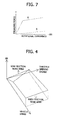
- FIG. 7 presents an example of a control map used in such a conventional 4WD vehicle, in which "T” of an axis of ordinates represents an engaging force of the torque distribution clutch mechanism, and " ⁇ N" of an axis of abscissas represents the rotational difference between the front wheels and the rear wheels.
- the engaging force T of the torque distribution clutch mechanism is increased by using the control map shown by a one-dotted line A of Fig. 7. Therefore, steady acceleration and start can be performed in the 4WD vehicle.
- an object of the present invention is to provide a four-wheel drive vehicle that is capable of improving the stability and traveling ability thereof even if it travels on a low friction road with prevention of the tight corner braking phenomenon.
- a four-wheel drive vehicle provides a torque distribution clutch mechanism which directly transmits the driving force generated from the engine to one of tow front wheels or two rear wheels, and which transmits it to the other wheels therethrough in order to control the engaging force in accordance with a traveling status of the four-wheel drive vehicle.
- the vehicle further comprises a tight corner judging means, a normal mode setting means, a low friction road judging means and a tight mode setting means.
- the tight corner judging means judges whether the vehicle travels at a large turning angle or not, and the normal mode setting means sets a normal mode to control the engaging force when it is judged by the tight corner judging means that the vehicle does not travel at the large turning angle.
- the low friction road judging means judges whether the vehicle travels on a low friction road or not, and the tight mode setting means for setting a tight mode to control the engaging force in a condition that it is judged by the tight comer judging means that the vehicle travels at the large turning angle when it is judged by the low friction road judging means that the vehicle dose not travel on the low friction road.
- the engaging force of the torque distribution clutch mechanism is set to the normal mode when it is judged that the vehicle travels on the low friction road.
- the engaging force of the torque distribution clutch mechanism is set to the normal mode even when the vehicle travels at the large turning angle.
- the vehicle is controlled with the normal mode, so that the driving force from the engine is adjustably distributed to the four wheels even through the torque distribution clutch mechanism if the vehicle travels at the large turning angle on the low friction road such snow road, crust road, sandy road and the like. Accordingly, the improved stability and traveling ability can be realized.
- the four-wheel drive vehicle further comprises a wheel speed sensor provided at each of the four wheels for detecting wheel speed of the each wheel.
- a rotational radius of the vehicle is calculated from the wheel speeds detected by the speed sensors is larger than a predetermined radius, and also a rotational difference between the front wheels and the rear wheels is calculated from the wheel speeds detected by the wheel speed sensors. Accordingly, whether the vehicle travels or not on the low friction road can be judged precisely.
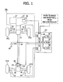
- Fig. 1 is an explanatory view showing a general construction of a four-wheel drive vehicle according to a first embodiment of the present invention.
- a driving torque from an engine 12 applies to front wheels FT1 and FT2, and is transmitted to rear wheels RT3 and RT4 in a condition that the driving torque is adjusted in accordance with a traveling status of the vehicle 10.
- a transmission 12 assembled aside of the engine 22 there is installed a front differential 15 in which a driving force from the engine 22 is outputted to an axle shaft 16 to drive the front wheels FT1 and FT2, and is transmitted to a propeller shaft 18.
- the propeller shaft 18 is connected to a rear differential 25 through a coupling 20.
- the coupling 20 provides a clutch mechanism 19 and is configured so as to be able to adjust the transmission of torque.
- the clutch mechanism 19 is controlled by a signal from an electric control circuit 50, so that the transmission torque can be adjusted.
- a torque distribution clutch mechanism consist of the clutch mechanism 19 and the coupling 20.
- the driving force from the coupling 20 drives the rear wheels RT3 and RT4 through the rear differential 25 and an axle shaft 26.
- wheel speed sensors S1, S2, S3 and S4 for detecting a wheel speed of the wheels, respectively.
- the electric control circuit 50 controls the coupling 20.
- the electric control circuit 50 is composed of a CPU 52 for executing a variety of calculation and control, a ROM 54 for storing control programs, a RAM 56 for serving as work areas of the CPU 52, and an input/output circuit 58.
- the electric control circuit 50 controls the torque transmitting force of the coupling 20 by detecting a slipping state between the front and rear wheels based upon output signals from the wheel speed sensors S1, S2, S3 and S4.
- the engaging force control map is organized from a normal pre-torque map and a normal mode map represented in Fig. 3(A) and from a tight pre-torque map and a tight mode map represented in Fig. 3(B).
- Each of the normal and tight pre-torque maps has a torque T1, a throttle opening degree and a vehicle speed as parameters. Namely, the torque T1 is led from the throttle opening degree (%) and the vehicle speed.
- the throttle opening degree represents the degree of depress amount of the acceleration pedal 64 detected by the acceleration pedal sensor 64a, changes from 0% to 100%, and is obtained by the acceleration operation signal from the acceleration pedal sensor 64a.
- the vehicle speed is calculated from an average of wheel speeds of the rear wheels RT3 and RT4 detected by the wheel speed sensors S3 and S4.
- an axis of ordinates represents an engaging force T2 (torque: N ⁇ m)
- an axis of abscissas represents a rotational difference ⁇ N (rpm) that is calculated from a difference between the average of the wheel speeds of the front wheels FT1 and FT2 and the average of the wheel speeds of the rear wheels RT3 and RT4.
- a normal state control is performed by a combination of the normal pre-torque map and the normal mode map
- a tight state control is performed by a combination of the tight pre-torque map and the tight mode map.
- the normal and tight mode maps may be so-called as an engaging force control map.
- the normal mode map shown in Fig. 3(A) is of the engaging force control map used when the four-wheel drive vehicle 10 travels in a normal condition, and has a characteristic that the engaging force T2 increases in accordance with the rotational difference ⁇ N. Namely, the engaging force T can be increased as the slip increases between the front and rear wheels, so that the driving force generated from the engine is distributed to the rear wheels in accordance with the engaging force T, whereby the slip of the front wheel is prevented and a steady acceleration of the vehicle is performed.
- the tight mode map shown in Fig. 3(B) is of the engaging force control map used when the four-wheel drive vehicle 10 is turned on a tight corner, and has a characteristic that the engaging force T is gradually increased relative to the increase of the rotational difference ⁇ N. Namely, the tight mode map is used when the vehicle 10 travels at a large turning angle, the engaging force T is diminished even if the rotational difference ⁇ N is large in a turning state of the vehicle 10. Therefore, a tight corner braking phenomenon can be prevented.
- a contexture of a low friction road judgment map used in the CPU 52 will be explained hereinafter with reference to Fig. 4.
- whether a low friction road is or not is judged from three parameters of the rotational difference ⁇ N between the front and rear wheels, the vehicle speed and the throttle opening degree by referring to the low friction road judgment map. It is judged to be on the low friction road in a case that the rotational difference ⁇ N is relatively large when the vehicle speed is low relative to the throttle opening degree. On the other hand, it is judged to be on a high friction road in a case that the rotational difference ⁇ N is relatively small when the vehicle speed is high relative to the throttle opening degree
- step S12 there are inputted rotational speeds ⁇ 1, ⁇ 2, ⁇ 3 and ⁇ 4 of the front wheels FT1 and FT2 and of the rear wheels RT3 and RT4 from the wheel speed sensors S1 S2, S3 and S4 (step S12).
- step S14 a turning radius of the vehicle 10 is calculated from the rotational speeds ⁇ 1, ⁇ 2, ⁇ 3 and ⁇ 4.
- step S16 the rotational difference ⁇ N between the front and rear wheels is calculated from the rotational speeds ⁇ 1, ⁇ 2, ⁇ 3 and ⁇ 4 in step S16.
- step S18 it is judged to be a large turning state when the turning radius calculated in step S14 is smaller than predetermined turning radius (10m, for example). Namely, it is judged whether the vehicle travels at the large turning angel in step S18.
- step S24 the engaging force T is, in step S24, determined by using the aforementioned tight mode map with reference to Fig. 3(B). After the determination in step S24, a control signal is outputted to control the clutch mechanism 19.
- step S18 the throttle opening degree is calculated in step S20 after the accelerator operation signal from the accelerator pedal sensor 64a attached on the accelerator pedal 64 is inputted into the CPU 52 through the input/output circuit 58.
- step S22 judged from the aforementioned vehicle speed, throttle opening degree and rotational difference ⁇ N between the front and rear wheels with reference to the above-mentioned low friction road judgment map shown in Fig. 4.
- step S26 the engaging force T is, in step S26, determined by using the aforementioned tight mode map with reference to Fig. 3(B).
- the control signal is outputted to control the clutch mechanism 19. With this control process, the engaging force T of the clutch mechanism 19 is diminished, so that the tight corner braking phenomenon can be prevented.
- step S24 the engaging force T is, in step S24, determined by using the aforementioned normal mode map with reference to Fig. 3(A).
- the control signal is outputted to control the clutch mechanism 19.
- the driving force is distributed to the four wheels (FT1, FT2, RT3 and RT4) by increasing the engaging force T of the clutch mechanism 19 corresponding to the rotational difference ⁇ N between the front wheels and the rear wheels. Accordingly, remarkable stability and traveling ability can be realized when the vehicle 10 travels at a low speed of the vehicle on the low friction road such snow road or sandy road.
- a four-wheel drive vehicle according to a second embodiment of the present invention will be explained hereinafter.
- a traveling mode selection switch 30 is provided with the vehicle to select a gear (speed) change pattern of an automatic transmission (14) in the second embodiment.
- a snow road traveling mode is provided in the traveling mode selection switch 30.
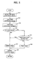
- FIG. 5 A process flow executed to control the engaging force T by the CPU 52 in the second embodiment will be explained hereinafter with reference to a flow chart shown in Fig. 5.
- the processing executed in steps S12-S16 are same as that of the aforementioned first embodiment shown in Fig. 2, so that the explanations thereabout is omitted herein.
- step S18 whether the large turning state (tight corner) is or not is judged by the CPU 52.
- the engaging force T is, in step S24, determined by using the aforementioned normal mode map shown in Fig. 3(A).
- a control signal is outputted to control the clutch mechanism 19 in step S28.
- step S23 judged whether the snow road traveling mode is selected or not.
- the engaging force T is, in step S26, determined by using the aforementioned tight mode map shown in Fig. 3(B), whereby a control signal is outputted to control the clutch mechanism 19 in step S28.
- the engaging force T of the clutch mechanism 19 is reduced, so that the tight corner braking phenomenon can be prevented.
- the engaging force T is, in step S24, determined by using the aforementioned normal mode map shown in Fig. 3(A), whereby a control signal is outputted to control the clutch mechanism 19 in step S28.
- the driving force is distributed to the four wheels (FT1, FT2, RT3 and RT4) by increasing the engaging force T of the clutch mechanism 19 corresponding to the rotational difference ⁇ N between the front wheels and the rear wheels. Accordingly, remarkable stability and traveling ability can be realized when the vehicle 10 travels on the low friction road such snow road or sandy road in the large turning state.
- a four-wheel drive vehicle according to a third embodiment of the present invention will be explained hereinafter.
- the electric control circuit 50 for the driving force distribution operation obtains such information corresponding to whether the vehicle travels or not on the low friction road from a control device for an ABS (Anti Break Skid) installed in the vehicle.
- ABS Anti Break Skid
- FIG. 5 A process flow executed to control the engaging force T by the CPU 52 in the third embodiment will be explained hereinafter with reference to a flow chart shown in Fig. 5.
- the processing executed in steps S12-S16 are same as that of the aforementioned first embodiment shown in Fig. 2, so that the explanations thereabout is omitted herein.
- step S18 whether the large turning state (tight corner) is or not is judged by the CPU 52.
- the engaging force T is, in step S24, determined by using the aforementioned normal mode map shown in Fig. 3(A).
- a control signal is outputted to control the clutch mechanism 19 in step S28.
- step S18 a road surface information ⁇ (friction between a road surface and the surface of the wheel) is inputted from the control device of the ABS to the CPU 52 through the input/output circuit 58 (in step S19).
- the engaging force T is, in step S26, determined by using the aforementioned tight mode map shown in Fig. 3(B), whereby a control signal is outputted to control the clutch mechanism 19 in step S28.
- the engaging force T of the clutch mechanism 19 is reduced, so that the tight corner braking phenomenon can be prevented.
- the engaging force T is, in step S24, determined by using the aforementioned normal mode map shown in Fig. 3(A), whereby a control signal is outputted to control the clutches 19 in step S28.
- the driving force is distributed to the four wheels (FT1, FT2, RT3 and RT4) by increasing the engaging force T of the clutch mechanism 19 corresponding to the rotational difference ⁇ N between the front and rear wheels. Accordingly, remarkable stability and traveling ability can be realized when the vehicle 10 travels on the low friction road such snow road or sandy road in the large turning state.
- the road surface information ⁇ may be obtained from ECU (Electric Control Unit) for engine control, for automatic transmission control and the like, and a navigation controller through an electric communication interface such as "CAN", “Been”, “J1850” and the like. Further, the snow road information may be obtained from the road information broadcast, whereby the snow road traveling mode is selected by its snow road information.
- ECU Electronic Control Unit
- a four-wheel drive vehicle provides a torque distribution clutch mechanism which directly transmits the driving force generated from the engine to one of tow front wheels or two rear wheels, and which transmits it to the other wheels therethrough in order to control the engaging force in accordance with a traveling status of the four-wheel drive vehicle.
- the vehicle further comprises a tight corner judging means, a normal mode setting means, a low friction road judging means and a tight mode setting means.
- the tight corner judging means judges whether the vehicle travels at a large turning angle or not, and the normal mode setting means sets a normal mode to control the engaging force when it is judged by the tight corner judging means that the vehicle does not travel at the large turning angle.
- the low friction road judging means judges whether the vehicle travels on a low friction road or not
- the tight mode setting means for setting a tight mode to control the engaging force in a condition that it is judged by the tight corner judging means that the vehicle travels at the large turning angle when it is judged by the low friction road judging means that the vehicle dose not travel on the low friction road.
Landscapes
- Engineering & Computer Science (AREA)
- General Engineering & Computer Science (AREA)
- Mechanical Engineering (AREA)
- Physics & Mathematics (AREA)
- Fluid Mechanics (AREA)
- Chemical & Material Sciences (AREA)
- Combustion & Propulsion (AREA)
- Transportation (AREA)
- Arrangement And Driving Of Transmission Devices (AREA)
Applications Claiming Priority (2)
| Application Number | Priority Date | Filing Date | Title |
|---|---|---|---|
| JP2002121056A JP2003312289A (ja) | 2002-04-23 | 2002-04-23 | 4輪駆動車 |
| JP2002121056 | 2002-04-23 |
Publications (3)
| Publication Number | Publication Date |
|---|---|
| EP1359044A2 true EP1359044A2 (de) | 2003-11-05 |
| EP1359044A3 EP1359044A3 (de) | 2006-05-31 |
| EP1359044B1 EP1359044B1 (de) | 2009-09-30 |
Family
ID=29208030
Family Applications (1)
| Application Number | Title | Priority Date | Filing Date |
|---|---|---|---|
| EP03009235A Expired - Lifetime EP1359044B1 (de) | 2002-04-23 | 2003-04-23 | Vierradgetriebenes Fahrzeug |
Country Status (4)
| Country | Link |
|---|---|
| US (1) | US6845838B2 (de) |
| EP (1) | EP1359044B1 (de) |
| JP (1) | JP2003312289A (de) |
| DE (1) | DE60329434D1 (de) |
Cited By (3)
| Publication number | Priority date | Publication date | Assignee | Title |
|---|---|---|---|---|
| WO2005052600A1 (en) * | 2003-11-20 | 2005-06-09 | Toyota Jidosha Kabushiki Kaisha | Vehicle running control apparatus and vehicle running control method |
| EP2554449A1 (de) * | 2011-08-01 | 2013-02-06 | Jtekt Corporation | Vorrichtung zur Schätzung des Reibungskoeffizienten eines Straßenbelags, Vorrichtung zur Steuerung der Antriebskraftverteilung und Fahrzeug mit Vierradantrieb |
| EP2617596A4 (de) * | 2010-09-15 | 2014-02-26 | Jtekt Corp | Fahrzeug mit vierradantrieb und steuervorrichtung dafür |
Families Citing this family (9)
| Publication number | Priority date | Publication date | Assignee | Title |
|---|---|---|---|---|
| JP4317716B2 (ja) * | 2003-07-08 | 2009-08-19 | 株式会社ジェイテクト | 4輪駆動車の駆動力配分制御装置 |
| JP4386171B2 (ja) * | 2003-12-04 | 2009-12-16 | 三菱自動車工業株式会社 | 4輪駆動車の動力伝達装置 |
| DE102004031259A1 (de) * | 2004-06-29 | 2006-01-19 | Zf Friedrichshafen Ag | Verfahren zur Lenkung eines Kraftfahrzeuges und Vorrichtung zur Durchführung des Verfahrens |
| JP2006088763A (ja) * | 2004-09-21 | 2006-04-06 | Toyota Motor Corp | 車両の制御装置 |
| JP5073537B2 (ja) * | 2008-03-06 | 2012-11-14 | 富士重工業株式会社 | 動力伝達装置 |
| JP5067243B2 (ja) | 2008-03-31 | 2012-11-07 | 株式会社ジェイテクト | 駆動力伝達装置、駆動力伝達装置の制御方法及び差動制限装置 |
| JP6435946B2 (ja) * | 2015-03-24 | 2018-12-12 | 株式会社ジェイテクト | 四輪駆動車及び四輪駆動車の制御装置 |
| JP6946630B2 (ja) * | 2016-10-04 | 2021-10-06 | 株式会社ジェイテクト | 駆動力伝達装置の制御装置及び路面状態判定装置 |
| JP7243448B2 (ja) * | 2019-05-24 | 2023-03-22 | マツダ株式会社 | 駆動力配分制御装置 |
Family Cites Families (11)
| Publication number | Priority date | Publication date | Assignee | Title |
|---|---|---|---|---|
| JP3268124B2 (ja) * | 1994-06-27 | 2002-03-25 | 富士重工業株式会社 | 車両のトルク配分制御装置 |
| GB2323940B (en) * | 1994-06-27 | 1999-01-20 | Fuji Heavy Ind Ltd | Vehicle driving torque distribution control system and method |
| JP3617680B2 (ja) * | 1995-01-31 | 2005-02-09 | 富士重工業株式会社 | 4輪駆動車のトラクション制御装置 |
| JPH1159216A (ja) * | 1997-08-26 | 1999-03-02 | Fuji Heavy Ind Ltd | 4輪駆動車の動力配分制御装置 |
| DE69935090T2 (de) * | 1998-06-09 | 2007-11-15 | Fuji Jukogyo K.K. | Drehmomentverteilungsregelsystem für ein allradgetriebenes Fahrzeug |
| DE19958772B4 (de) * | 1999-12-07 | 2011-07-21 | Robert Bosch GmbH, 70469 | Verfahren und Vorrichtung zur Antriebsschlupfregelung (ASR) eines Kraftfahrzeugs in Abhängigkeit von Kurvenradius und Querbeschleunigung |
| JP2001260836A (ja) * | 2000-03-23 | 2001-09-26 | Toyota Motor Corp | 車両用駆動力配分制御装置 |
| IT1320394B1 (it) * | 2000-06-05 | 2003-11-26 | Fiat Ricerche | Sistema per il controllo attivo di un differenziale di un autoveicolo. |
| JP3719116B2 (ja) * | 2000-08-30 | 2005-11-24 | トヨタ自動車株式会社 | 車輌の駆動力制御装置 |
| JP2002127773A (ja) * | 2000-10-20 | 2002-05-08 | Fuji Heavy Ind Ltd | 4輪駆動車の駆動力配分装置 |
| JP4456748B2 (ja) * | 2000-10-27 | 2010-04-28 | 富士重工業株式会社 | 4輪駆動車の動力配分制御装置 |
-
2002
- 2002-04-23 JP JP2002121056A patent/JP2003312289A/ja active Pending
-
2003
- 2003-04-23 US US10/420,891 patent/US6845838B2/en not_active Expired - Lifetime
- 2003-04-23 EP EP03009235A patent/EP1359044B1/de not_active Expired - Lifetime
- 2003-04-23 DE DE60329434T patent/DE60329434D1/de not_active Expired - Lifetime
Cited By (7)
| Publication number | Priority date | Publication date | Assignee | Title |
|---|---|---|---|---|
| WO2005052600A1 (en) * | 2003-11-20 | 2005-06-09 | Toyota Jidosha Kabushiki Kaisha | Vehicle running control apparatus and vehicle running control method |
| US7376503B2 (en) | 2003-11-20 | 2008-05-20 | Toyota Jidosha Kabushiki Kaisha | Vehicle running control apparatus and vehicle running control method |
| CN100432672C (zh) * | 2003-11-20 | 2008-11-12 | 丰田自动车株式会社 | 车辆行驶控制装置和车辆行驶控制方法 |
| EP2617596A4 (de) * | 2010-09-15 | 2014-02-26 | Jtekt Corp | Fahrzeug mit vierradantrieb und steuervorrichtung dafür |
| US8825324B2 (en) | 2010-09-15 | 2014-09-02 | Jtekt Corporation | Four-wheel-drive vehicle and control unit |
| EP2554449A1 (de) * | 2011-08-01 | 2013-02-06 | Jtekt Corporation | Vorrichtung zur Schätzung des Reibungskoeffizienten eines Straßenbelags, Vorrichtung zur Steuerung der Antriebskraftverteilung und Fahrzeug mit Vierradantrieb |
| US8700280B2 (en) | 2011-08-01 | 2014-04-15 | Jtekt Corporation | Road surface frictional coefficient estimation device, driving force distribution control device and four-wheel-drive vehicle |
Also Published As
| Publication number | Publication date |
|---|---|
| DE60329434D1 (de) | 2009-11-12 |
| US6845838B2 (en) | 2005-01-25 |
| EP1359044B1 (de) | 2009-09-30 |
| JP2003312289A (ja) | 2003-11-06 |
| US20040016585A1 (en) | 2004-01-29 |
| EP1359044A3 (de) | 2006-05-31 |
Similar Documents
| Publication | Publication Date | Title |
|---|---|---|
| US6564139B2 (en) | Apparatus and method for controlling a four-wheel drive vehicle | |
| EP2591937B1 (de) | Drehmomentverteilungs-steuervorrichtung für ein fahrzeug mit vierradantrieb | |
| EP1127726A2 (de) | Steuerung zum Verteilen der Antriebskraft und Steuerungsverfahren für vierradangetriebene Fahrzeuge | |
| US7832518B2 (en) | Torque distribution control in a motor vehicle | |
| EP2591941A1 (de) | Vorrichtung zur steuerung der drehmomentverteilung auf die linken und die rechten räder eines fahrzeugs | |
| US6845838B2 (en) | Four-wheel drive vehicle | |
| US7048084B2 (en) | Power distribution control apparatus of four-wheel drive vehicle | |
| JPH1089383A (ja) | オーバーランにおける走行安定性を改善する方法及び装置 | |
| JP3467973B2 (ja) | 駆動力配分制御装置 | |
| JP2017087786A (ja) | 四輪駆動車両の制御装置 | |
| US7290636B2 (en) | Device and method for controlling distribution of drive force of four-wheel drive car | |
| JPH0227124A (ja) | 自動車のスリップ制御装置 | |
| JP3430495B2 (ja) | 4輪駆動車の制御装置 | |
| JP3412313B2 (ja) | 4輪駆動車の駆動力分配制御装置 | |
| JP3575223B2 (ja) | 車両用駆動力制御装置 | |
| JP3622257B2 (ja) | 車両用駆動力制御装置 | |
| JP2000085393A (ja) | 4輪駆動車 | |
| JP3424768B2 (ja) | 左右輪と前後輪の駆動力配分総合制御装置 | |
| JP3301220B2 (ja) | 左右輪と前後輪の駆動力配分総合制御装置 | |
| JP2861611B2 (ja) | 車両用左右駆動力制御装置 | |
| JP3430494B2 (ja) | 4輪駆動車の制御装置 | |
| JP3506223B2 (ja) | 四輪駆動車の駆動力配分制御装置 | |
| WO2002036383B1 (en) | Motor vehicle and a method for propelling the same | |
| JPH0472444A (ja) | 駆動力制御装置 | |
| JPH08207606A (ja) | 4輪駆動車の駆動力分配制御装置 |
Legal Events
| Date | Code | Title | Description |
|---|---|---|---|
| PUAI | Public reference made under article 153(3) epc to a published international application that has entered the european phase |
Free format text: ORIGINAL CODE: 0009012 |
|
| AK | Designated contracting states |
Kind code of ref document: A2 Designated state(s): AT BE BG CH CY CZ DE DK EE ES FI FR GB GR HU IE IT LI LU MC NL PT RO SE SI SK TR |
|
| AX | Request for extension of the european patent |
Extension state: AL LT LV MK |
|
| PUAL | Search report despatched |
Free format text: ORIGINAL CODE: 0009013 |
|
| AK | Designated contracting states |
Kind code of ref document: A3 Designated state(s): AT BE BG CH CY CZ DE DK EE ES FI FR GB GR HU IE IT LI LU MC NL PT RO SE SI SK TR |
|
| AX | Request for extension of the european patent |
Extension state: AL LT LV MK |
|
| RAP1 | Party data changed (applicant data changed or rights of an application transferred) |
Owner name: JTEKT CORPORATION |
|
| RIN1 | Information on inventor provided before grant (corrected) |
Inventor name: WAKAO, HISAAKI,C/O JTEKT CORPORATION Inventor name: IMAI, FUKAMI,C/O JTEKT CORPORATION |
|
| 17P | Request for examination filed |
Effective date: 20061120 |
|
| AKX | Designation fees paid |
Designated state(s): DE FR GB |
|
| 17Q | First examination report despatched |
Effective date: 20070209 |
|
| GRAP | Despatch of communication of intention to grant a patent |
Free format text: ORIGINAL CODE: EPIDOSNIGR1 |
|
| GRAS | Grant fee paid |
Free format text: ORIGINAL CODE: EPIDOSNIGR3 |
|
| GRAA | (expected) grant |
Free format text: ORIGINAL CODE: 0009210 |
|
| AK | Designated contracting states |
Kind code of ref document: B1 Designated state(s): DE FR GB |
|
| REG | Reference to a national code |
Ref country code: GB Ref legal event code: FG4D |
|
| REF | Corresponds to: |
Ref document number: 60329434 Country of ref document: DE Date of ref document: 20091112 Kind code of ref document: P |
|
| PLBE | No opposition filed within time limit |
Free format text: ORIGINAL CODE: 0009261 |
|
| STAA | Information on the status of an ep patent application or granted ep patent |
Free format text: STATUS: NO OPPOSITION FILED WITHIN TIME LIMIT |
|
| 26N | No opposition filed |
Effective date: 20100701 |
|
| GBPC | Gb: european patent ceased through non-payment of renewal fee |
Effective date: 20100423 |
|
| PG25 | Lapsed in a contracting state [announced via postgrant information from national office to epo] |
Ref country code: GB Free format text: LAPSE BECAUSE OF NON-PAYMENT OF DUE FEES Effective date: 20100423 |
|
| REG | Reference to a national code |
Ref country code: FR Ref legal event code: PLFP Year of fee payment: 14 |
|
| REG | Reference to a national code |
Ref country code: FR Ref legal event code: PLFP Year of fee payment: 15 |
|
| REG | Reference to a national code |
Ref country code: FR Ref legal event code: PLFP Year of fee payment: 16 |
|
| PGFP | Annual fee paid to national office [announced via postgrant information from national office to epo] |
Ref country code: FR Payment date: 20220308 Year of fee payment: 20 |
|
| PGFP | Annual fee paid to national office [announced via postgrant information from national office to epo] |
Ref country code: DE Payment date: 20220302 Year of fee payment: 20 |
|
| REG | Reference to a national code |
Ref country code: DE Ref legal event code: R071 Ref document number: 60329434 Country of ref document: DE |