EP1359314A1 - Ensemble d'injecteur étalonné pour l'alimentation d'un moteur à combustion interne, notamment d'un générateur électrique - Google Patents
Ensemble d'injecteur étalonné pour l'alimentation d'un moteur à combustion interne, notamment d'un générateur électrique Download PDFInfo
- Publication number
- EP1359314A1 EP1359314A1 EP03008777A EP03008777A EP1359314A1 EP 1359314 A1 EP1359314 A1 EP 1359314A1 EP 03008777 A EP03008777 A EP 03008777A EP 03008777 A EP03008777 A EP 03008777A EP 1359314 A1 EP1359314 A1 EP 1359314A1
- Authority
- EP
- European Patent Office
- Prior art keywords
- cavity
- holes
- fuel
- box
- duct
- Prior art date
- Legal status (The legal status is an assumption and is not a legal conclusion. Google has not performed a legal analysis and makes no representation as to the accuracy of the status listed.)
- Granted
Links
- 238000002485 combustion reaction Methods 0.000 title claims abstract description 19
- 239000000446 fuel Substances 0.000 claims abstract description 20
- 238000005192 partition Methods 0.000 claims description 11
- 239000010687 lubricating oil Substances 0.000 claims description 3
- 239000002360 explosive Substances 0.000 description 2
- 239000012530 fluid Substances 0.000 description 2
- 230000001133 acceleration Effects 0.000 description 1
- 238000006243 chemical reaction Methods 0.000 description 1
- 230000000670 limiting effect Effects 0.000 description 1
- 230000001050 lubricating effect Effects 0.000 description 1
- 239000000463 material Substances 0.000 description 1
- 230000004048 modification Effects 0.000 description 1
- 238000012986 modification Methods 0.000 description 1
- 239000003921 oil Substances 0.000 description 1
- 230000002093 peripheral effect Effects 0.000 description 1
- 230000035939 shock Effects 0.000 description 1
Images
Classifications
-
- F—MECHANICAL ENGINEERING; LIGHTING; HEATING; WEAPONS; BLASTING
- F02—COMBUSTION ENGINES; HOT-GAS OR COMBUSTION-PRODUCT ENGINE PLANTS
- F02M—SUPPLYING COMBUSTION ENGINES IN GENERAL WITH COMBUSTIBLE MIXTURES OR CONSTITUENTS THEREOF
- F02M35/00—Combustion-air cleaners, air intakes, intake silencers, or induction systems specially adapted for, or arranged on, internal-combustion engines
- F02M35/10—Air intakes; Induction systems
- F02M35/1015—Air intakes; Induction systems characterised by the engine type
- F02M35/1019—Two-stroke engines; Reverse-flow scavenged or cross scavenged engines
-
- F—MECHANICAL ENGINEERING; LIGHTING; HEATING; WEAPONS; BLASTING
- F02—COMBUSTION ENGINES; HOT-GAS OR COMBUSTION-PRODUCT ENGINE PLANTS
- F02B—INTERNAL-COMBUSTION PISTON ENGINES; COMBUSTION ENGINES IN GENERAL
- F02B63/00—Adaptations of engines for driving pumps, hand-held tools or electric generators; Portable combinations of engines with engine-driven devices
- F02B63/04—Adaptations of engines for driving pumps, hand-held tools or electric generators; Portable combinations of engines with engine-driven devices for electric generators
-
- F—MECHANICAL ENGINEERING; LIGHTING; HEATING; WEAPONS; BLASTING
- F02—COMBUSTION ENGINES; HOT-GAS OR COMBUSTION-PRODUCT ENGINE PLANTS
- F02M—SUPPLYING COMBUSTION ENGINES IN GENERAL WITH COMBUSTIBLE MIXTURES OR CONSTITUENTS THEREOF
- F02M35/00—Combustion-air cleaners, air intakes, intake silencers, or induction systems specially adapted for, or arranged on, internal-combustion engines
- F02M35/10—Air intakes; Induction systems
- F02M35/10006—Air intakes; Induction systems characterised by the position of elements of the air intake system in direction of the air intake flow, i.e. between ambient air inlet and supply to the combustion chamber
- F02M35/10026—Plenum chambers
- F02M35/10045—Multiple plenum chambers; Plenum chambers having inner separation walls
-
- F—MECHANICAL ENGINEERING; LIGHTING; HEATING; WEAPONS; BLASTING
- F02—COMBUSTION ENGINES; HOT-GAS OR COMBUSTION-PRODUCT ENGINE PLANTS
- F02M—SUPPLYING COMBUSTION ENGINES IN GENERAL WITH COMBUSTIBLE MIXTURES OR CONSTITUENTS THEREOF
- F02M35/00—Combustion-air cleaners, air intakes, intake silencers, or induction systems specially adapted for, or arranged on, internal-combustion engines
- F02M35/10—Air intakes; Induction systems
- F02M35/10006—Air intakes; Induction systems characterised by the position of elements of the air intake system in direction of the air intake flow, i.e. between ambient air inlet and supply to the combustion chamber
- F02M35/10026—Plenum chambers
- F02M35/10052—Plenum chambers special shapes or arrangements of plenum chambers; Constructional details
-
- F—MECHANICAL ENGINEERING; LIGHTING; HEATING; WEAPONS; BLASTING
- F02—COMBUSTION ENGINES; HOT-GAS OR COMBUSTION-PRODUCT ENGINE PLANTS
- F02M—SUPPLYING COMBUSTION ENGINES IN GENERAL WITH COMBUSTIBLE MIXTURES OR CONSTITUENTS THEREOF
- F02M35/00—Combustion-air cleaners, air intakes, intake silencers, or induction systems specially adapted for, or arranged on, internal-combustion engines
- F02M35/10—Air intakes; Induction systems
- F02M35/1015—Air intakes; Induction systems characterised by the engine type
- F02M35/1017—Small engines, e.g. for handheld tools, or model engines; Single cylinder engines
-
- F—MECHANICAL ENGINEERING; LIGHTING; HEATING; WEAPONS; BLASTING
- F02—COMBUSTION ENGINES; HOT-GAS OR COMBUSTION-PRODUCT ENGINE PLANTS
- F02M—SUPPLYING COMBUSTION ENGINES IN GENERAL WITH COMBUSTIBLE MIXTURES OR CONSTITUENTS THEREOF
- F02M35/00—Combustion-air cleaners, air intakes, intake silencers, or induction systems specially adapted for, or arranged on, internal-combustion engines
- F02M35/10—Air intakes; Induction systems
- F02M35/1015—Air intakes; Induction systems characterised by the engine type
- F02M35/10177—Engines having multiple fuel injectors or carburettors per cylinder
-
- F—MECHANICAL ENGINEERING; LIGHTING; HEATING; WEAPONS; BLASTING
- F02—COMBUSTION ENGINES; HOT-GAS OR COMBUSTION-PRODUCT ENGINE PLANTS
- F02M—SUPPLYING COMBUSTION ENGINES IN GENERAL WITH COMBUSTIBLE MIXTURES OR CONSTITUENTS THEREOF
- F02M35/00—Combustion-air cleaners, air intakes, intake silencers, or induction systems specially adapted for, or arranged on, internal-combustion engines
- F02M35/10—Air intakes; Induction systems
- F02M35/10209—Fluid connections to the air intake system; their arrangement of pipes, valves or the like
- F02M35/10216—Fuel injectors; Fuel pipes or rails; Fuel pumps or pressure regulators
-
- F—MECHANICAL ENGINEERING; LIGHTING; HEATING; WEAPONS; BLASTING
- F02—COMBUSTION ENGINES; HOT-GAS OR COMBUSTION-PRODUCT ENGINE PLANTS
- F02M—SUPPLYING COMBUSTION ENGINES IN GENERAL WITH COMBUSTIBLE MIXTURES OR CONSTITUENTS THEREOF
- F02M35/00—Combustion-air cleaners, air intakes, intake silencers, or induction systems specially adapted for, or arranged on, internal-combustion engines
- F02M35/10—Air intakes; Induction systems
- F02M35/10209—Fluid connections to the air intake system; their arrangement of pipes, valves or the like
- F02M35/10222—Exhaust gas recirculation [EGR]; Positive crankcase ventilation [PCV]; Additional air admission, lubricant or fuel vapour admission
-
- F—MECHANICAL ENGINEERING; LIGHTING; HEATING; WEAPONS; BLASTING
- F02—COMBUSTION ENGINES; HOT-GAS OR COMBUSTION-PRODUCT ENGINE PLANTS
- F02M—SUPPLYING COMBUSTION ENGINES IN GENERAL WITH COMBUSTIBLE MIXTURES OR CONSTITUENTS THEREOF
- F02M35/00—Combustion-air cleaners, air intakes, intake silencers, or induction systems specially adapted for, or arranged on, internal-combustion engines
- F02M35/12—Intake silencers ; Sound modulation, transmission or amplification
- F02M35/1205—Flow throttling or guiding
- F02M35/1216—Flow throttling or guiding by using a plurality of holes, slits, protrusions, perforations, ribs or the like; Surface structures; Turbulence generators
-
- F—MECHANICAL ENGINEERING; LIGHTING; HEATING; WEAPONS; BLASTING
- F02—COMBUSTION ENGINES; HOT-GAS OR COMBUSTION-PRODUCT ENGINE PLANTS
- F02M—SUPPLYING COMBUSTION ENGINES IN GENERAL WITH COMBUSTIBLE MIXTURES OR CONSTITUENTS THEREOF
- F02M35/00—Combustion-air cleaners, air intakes, intake silencers, or induction systems specially adapted for, or arranged on, internal-combustion engines
- F02M35/16—Combustion-air cleaners, air intakes, intake silencers, or induction systems specially adapted for, or arranged on, internal-combustion engines characterised by use in vehicles
-
- F—MECHANICAL ENGINEERING; LIGHTING; HEATING; WEAPONS; BLASTING
- F02—COMBUSTION ENGINES; HOT-GAS OR COMBUSTION-PRODUCT ENGINE PLANTS
- F02B—INTERNAL-COMBUSTION PISTON ENGINES; COMBUSTION ENGINES IN GENERAL
- F02B75/00—Other engines
- F02B75/02—Engines characterised by their cycles, e.g. six-stroke
- F02B2075/022—Engines characterised by their cycles, e.g. six-stroke having less than six strokes per cycle
- F02B2075/025—Engines characterised by their cycles, e.g. six-stroke having less than six strokes per cycle two
Definitions
- the present invention relates to a calibrated injector assembly for feeding internal-combustion engines, particularly for electric power generators, therefore for engines adapted to run at a constant speed.
- Electric power generators are known which are powered by a single-cylinder internal-combustion engine and are typically used to recharge batteries of campers or the like.
- the engines used in such electric power generators are characterized in that they have their maximum conversion efficiency by turning at a constant rotation rate, at which the efficiency of the entire electric power generator is optimized.
- the aim of the present invention is therefore to provide a fuel injector assembly that has a considerably simplified structure with respect to conventional carburetors used in internal-combustion engines.
- An object of the present invention is to reduce the intake noise caused by the shock wave that follows the combustion stroke of the engine.
- Another object of the present invention is to provide an injector assembly that is particularly suitable for mixing gaseous fuel.
- the present calibrated injector assembly for feeding internal-combustion engines, particularly for electric power generators, characterized in that it comprises a box-like body that forms internally a cavity, a duct for connecting said cavity to a combustion chamber of said engine, at least one nozzle for feeding fuel into said box-like body proximate to the inlet to said duct, and a plurality of holes formed in said box-like body for feeding combustion-supporting air into said cavity, said holes being formed in order to ensure a given stoichiometric ratio with respect to said fuel.
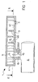
- the reference numeral 1 generally designates a calibrated injector assembly for feeding two-stroke internal-combustion engines, particularly for electric power generators.
- Such assembly 1 feeds the two-stroke internal-combustion engine 2, to which it is rigidly fixed by means of a bracket 3.
- the internal-combustion engine is not shown in detail, since it is fully conventional.
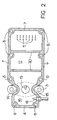
- the multiple injector assembly 1 is constituted by a metallic box-like body, which is substantially shaped like a prism with a rectangular base and is composed of a tray 4 which encloses a cavity 6 together with a lid 5.
- the tray 4 and the lid 5 are fixed one another by way of screws (not shown), which engage in threaded holes 8 of a peripheral wall 7 of the tray 4.
- the tray 4 comprises a substantially rectangular bottom 9, in a portion 10 of which there are multiple calibrated holes 11 arranged along multiple rows.
- the longitudinal walls of the tray 4 form, at the hole for entering the duct 13, two respective bends 14 and 15, which ideally divide the cavity 6 into two chambers 16 and 17, the first whereof is smaller than the second.
- a calibrated nozzle 18 is arranged on a lateral surface of the chamber 16 and is suitable to introduce the fuel.
- a second calibrated nozzle 19 is fixed to the duct 13, and oil for lubricating the combustion chamber of the internal-combustion engine 2 is introduced through the second nozzle.
- Three partitions 20 are provided inside the cavity 6 and are arranged transversely to the length of the box-like body; two of such partitions extend from one side wall 7 of the tray 4 to the other and are fixed to the tray 4, while the remaining partition, which also has the same dimensions, is fixed to the lid 5.
- Operation of the invention is as follows: air is aspirated through the calibrated holes 11 into the cavity 6, at the end of the chamber 17; the calibration is such that the holes 11 allow the inflow of an amount of air that is equal to the amount required in order to provide the correct stoichiometric ratio with the fuel, particularly gaseous fuel, introduced with a constant flow-rate by the calibrated nozzle 18.
- the path is such that every fluid thread of the air stream is subjected to an alternated sequence of positive and negative accelerations and of direction changes owing to the presence of the partitions 20; the motion of said fluid thread is of the turbulent type.
- the air after entering the chamber 17 of the cavity 6, mixes with the fuel introduced through the nozzle 18 into the chamber 16. It should be noted that the larger quantity of air that arrives from the chamber 17 gathers, due to the suction of the engine, directly in the duct 13, facilitating correct mixing.
- the resulting mix of air and fuel is aspirated into the intake duct 13, where the nozzle 19 introduces the lubricating oil at a constant flow-rate.
- the mix of air and fuel in which the lubricating oil is suspended advances along the intake duct until it is introduced in the cylinder of the two-stroke internal-combustion engine 2.
- the invention allows to provide a carburetor that has no moving parts (comparable to the throttle valve of conventional internal-combustion engines) and is therefore constructively extremely simple and highly effective in obtaining an explosive air-gas mix.
- Such a condition is achieved by providing a larger number of calibrated holes in the lower surface of the tray 4, in the portion 10.
- Those holes can be partially closed, according to a number of variations equal to the number of said operating states of the engine, by means of a partition that is actuated in a gate-like fashion: said partition can, for example, be able to slide within a guide and can be locked along said guide in the positions that correspond to each one of the partial closures of the holes that provide the air supply that is required in each instance.
- the number of the calibrated nozzles for introducing fuel is equal to the number of said operating states of the engine that one wishes to provide: only one of said nozzles might operate in order to provide the minimum-speed condition (which corresponds to the minimum opening of the calibrated holes on the part of the movable partition), or two or more of said nozzles, taken in pairs, can operate simultaneously for the other operating states, which are characterized by higher engine speeds (which correspond to larger openings of the calibrated holes on the part of the movable partition).
Landscapes
- Engineering & Computer Science (AREA)
- Chemical & Material Sciences (AREA)
- Combustion & Propulsion (AREA)
- Mechanical Engineering (AREA)
- General Engineering & Computer Science (AREA)
- Physics & Mathematics (AREA)
- Geometry (AREA)
- Fuel-Injection Apparatus (AREA)
Applications Claiming Priority (2)
| Application Number | Priority Date | Filing Date | Title |
|---|---|---|---|
| ITBO20020251 | 2002-04-30 | ||
| IT2002BO000251A ITBO20020251A1 (it) | 2002-04-30 | 2002-04-30 | Gruppo iniettore calibrato per l'alimentazione di un motore a scoppioin particolare per gruppi elettrogeni |
Publications (2)
| Publication Number | Publication Date |
|---|---|
| EP1359314A1 true EP1359314A1 (fr) | 2003-11-05 |
| EP1359314B1 EP1359314B1 (fr) | 2007-08-01 |
Family
ID=11440097
Family Applications (1)
| Application Number | Title | Priority Date | Filing Date |
|---|---|---|---|
| EP03008777A Expired - Lifetime EP1359314B1 (fr) | 2002-04-30 | 2003-04-22 | Ensemble d'injecteur étalonné pour l'alimentation d'un moteur à combustion interne, notamment d'un générateur électrique |
Country Status (3)
| Country | Link |
|---|---|
| EP (1) | EP1359314B1 (fr) |
| DE (1) | DE60315214D1 (fr) |
| IT (1) | ITBO20020251A1 (fr) |
Cited By (2)
| Publication number | Priority date | Publication date | Assignee | Title |
|---|---|---|---|---|
| RU2378529C2 (ru) * | 2007-04-10 | 2010-01-10 | Юрий Васильевич Тулаев | Форсунка для насосного и пневматического распыливания топлива |
| CN105927430A (zh) * | 2016-06-21 | 2016-09-07 | 刘联合 | 功率燃料自动同步调节转换器 |
Citations (7)
| Publication number | Priority date | Publication date | Assignee | Title |
|---|---|---|---|---|
| FR2430520A1 (fr) * | 1978-07-07 | 1980-02-01 | Mitsubishi Motors Corp | Systeme d'admission pour moteur a combustion interne |
| EP0063632A1 (fr) * | 1981-04-29 | 1982-11-03 | Yamaha Motor Co., Ltd. | Dispositif d'admission pour moteur à combustion interne |
| US4364340A (en) * | 1980-02-08 | 1982-12-21 | Yamaha Hatsudoki Kabushiki Kaisha | Vehicular engine |
| EP0832352A2 (fr) * | 1995-06-13 | 1998-04-01 | FILTERWERK MANN + HUMMEL GmbH | Module de tuyau |
| JP2000130274A (ja) * | 1998-10-27 | 2000-05-09 | Toyota Motor Corp | エンジンの吸気装置 |
| JP2000220544A (ja) * | 1999-01-28 | 2000-08-08 | Haruo Wada | エンジンの吸気装置 |
| JP2000345932A (ja) * | 1999-06-03 | 2000-12-12 | Toyota Auto Body Co Ltd | 車両の吸気音低減装置 |
-
2002
- 2002-04-30 IT IT2002BO000251A patent/ITBO20020251A1/it unknown
-
2003
- 2003-04-22 DE DE60315214T patent/DE60315214D1/de not_active Expired - Lifetime
- 2003-04-22 EP EP03008777A patent/EP1359314B1/fr not_active Expired - Lifetime
Patent Citations (7)
| Publication number | Priority date | Publication date | Assignee | Title |
|---|---|---|---|---|
| FR2430520A1 (fr) * | 1978-07-07 | 1980-02-01 | Mitsubishi Motors Corp | Systeme d'admission pour moteur a combustion interne |
| US4364340A (en) * | 1980-02-08 | 1982-12-21 | Yamaha Hatsudoki Kabushiki Kaisha | Vehicular engine |
| EP0063632A1 (fr) * | 1981-04-29 | 1982-11-03 | Yamaha Motor Co., Ltd. | Dispositif d'admission pour moteur à combustion interne |
| EP0832352A2 (fr) * | 1995-06-13 | 1998-04-01 | FILTERWERK MANN + HUMMEL GmbH | Module de tuyau |
| JP2000130274A (ja) * | 1998-10-27 | 2000-05-09 | Toyota Motor Corp | エンジンの吸気装置 |
| JP2000220544A (ja) * | 1999-01-28 | 2000-08-08 | Haruo Wada | エンジンの吸気装置 |
| JP2000345932A (ja) * | 1999-06-03 | 2000-12-12 | Toyota Auto Body Co Ltd | 車両の吸気音低減装置 |
Cited By (3)
| Publication number | Priority date | Publication date | Assignee | Title |
|---|---|---|---|---|
| RU2378529C2 (ru) * | 2007-04-10 | 2010-01-10 | Юрий Васильевич Тулаев | Форсунка для насосного и пневматического распыливания топлива |
| CN105927430A (zh) * | 2016-06-21 | 2016-09-07 | 刘联合 | 功率燃料自动同步调节转换器 |
| CN105927430B (zh) * | 2016-06-21 | 2018-11-06 | 刘联合 | 功率燃料自动同步调节转换器 |
Also Published As
| Publication number | Publication date |
|---|---|
| EP1359314B1 (fr) | 2007-08-01 |
| ITBO20020251A0 (it) | 2002-04-30 |
| ITBO20020251A1 (it) | 2003-10-30 |
| DE60315214D1 (de) | 2007-09-13 |
Similar Documents
| Publication | Publication Date | Title |
|---|---|---|
| US10184368B2 (en) | Breather device for internal combustion engine | |
| CN100422542C (zh) | 吸气装置 | |
| SE0000095D0 (sv) | Spjäll för reglering av tillsatsluft till tvåtakts förbränningsmotorer | |
| KR20010091839A (ko) | 적어도 두 개의 흡기 밸브를 갖는 4-행정 내연기관 | |
| KR100238639B1 (ko) | 2사이클 내연기관 | |
| JP5957217B2 (ja) | 2サイクルエンジン | |
| EP1359314B1 (fr) | Ensemble d'injecteur étalonné pour l'alimentation d'un moteur à combustion interne, notamment d'un générateur électrique | |
| US6645022B2 (en) | Outboard motor | |
| GB2321672A (en) | Venting device with integrated oil separator for a crankcase of an internal combustion engine | |
| US4697569A (en) | Intake system for a multi-cylinder internal combustion engine | |
| JPS57183521A (en) | Intake device for internal combustion engine | |
| EP2625414B1 (fr) | Appareil d'apport d'air pour moteur à combustion à deux temps | |
| KR840000730A (ko) | 토오치 점화식 가솔린 내연기관 | |
| US4516538A (en) | Intake manifold for internal combustion engines | |
| JP2006283758A (ja) | 2サイクルエンジン | |
| US6745739B2 (en) | Intake system of an engine | |
| JPS5644419A (en) | Device for improving combustion of mixture in four-cycle internal combustion engine | |
| ES531473A0 (es) | Perfeccionamientos en un motor de combustion interna | |
| JP2006257976A (ja) | 内燃機関の吸気装置 | |
| JPS5925064A (ja) | 多連気化器における始動装置 | |
| SU1315640A1 (ru) | Система питани дл двигател внутреннего сгорани | |
| RU2029878C1 (ru) | Двигатель внутреннего сгорания | |
| JPS6412987A (en) | Motorcycle | |
| SU802588A1 (ru) | Карбюратор дл двигател внут-РЕННЕгО СгОРАНи | |
| KR930019984A (ko) | 디이젤기관의 소기실구조 |
Legal Events
| Date | Code | Title | Description |
|---|---|---|---|
| PUAI | Public reference made under article 153(3) epc to a published international application that has entered the european phase |
Free format text: ORIGINAL CODE: 0009012 |
|
| AK | Designated contracting states |
Kind code of ref document: A1 Designated state(s): AT BE BG CH CY CZ DE DK EE ES FI FR GB GR HU IE IT LI LU MC NL PT RO SE SI SK TR |
|
| AX | Request for extension of the european patent |
Extension state: AL LT LV MK |
|
| 17P | Request for examination filed |
Effective date: 20040323 |
|
| AKX | Designation fees paid |
Designated state(s): DE FR IT |
|
| GRAP | Despatch of communication of intention to grant a patent |
Free format text: ORIGINAL CODE: EPIDOSNIGR1 |
|
| GRAS | Grant fee paid |
Free format text: ORIGINAL CODE: EPIDOSNIGR3 |
|
| GRAA | (expected) grant |
Free format text: ORIGINAL CODE: 0009210 |
|
| AK | Designated contracting states |
Kind code of ref document: B1 Designated state(s): DE FR IT |
|
| REF | Corresponds to: |
Ref document number: 60315214 Country of ref document: DE Date of ref document: 20070913 Kind code of ref document: P |
|
| EN | Fr: translation not filed | ||
| PLBE | No opposition filed within time limit |
Free format text: ORIGINAL CODE: 0009261 |
|
| STAA | Information on the status of an ep patent application or granted ep patent |
Free format text: STATUS: NO OPPOSITION FILED WITHIN TIME LIMIT |
|
| 26N | No opposition filed |
Effective date: 20080506 |
|
| PG25 | Lapsed in a contracting state [announced via postgrant information from national office to epo] |
Ref country code: FR Free format text: LAPSE BECAUSE OF FAILURE TO SUBMIT A TRANSLATION OF THE DESCRIPTION OR TO PAY THE FEE WITHIN THE PRESCRIBED TIME-LIMIT Effective date: 20080328 Ref country code: DE Free format text: LAPSE BECAUSE OF FAILURE TO SUBMIT A TRANSLATION OF THE DESCRIPTION OR TO PAY THE FEE WITHIN THE PRESCRIBED TIME-LIMIT Effective date: 20071103 |
|
| PGFP | Annual fee paid to national office [announced via postgrant information from national office to epo] |
Ref country code: IT Payment date: 20180420 Year of fee payment: 16 |
|
| PG25 | Lapsed in a contracting state [announced via postgrant information from national office to epo] |
Ref country code: IT Free format text: LAPSE BECAUSE OF NON-PAYMENT OF DUE FEES Effective date: 20190422 |