EP1359841B1 - Systeme permettant de controler la concentration d'analytes dans des fluides corporels - Google Patents
Systeme permettant de controler la concentration d'analytes dans des fluides corporels Download PDFInfo
- Publication number
- EP1359841B1 EP1359841B1 EP02711825A EP02711825A EP1359841B1 EP 1359841 B1 EP1359841 B1 EP 1359841B1 EP 02711825 A EP02711825 A EP 02711825A EP 02711825 A EP02711825 A EP 02711825A EP 1359841 B1 EP1359841 B1 EP 1359841B1
- Authority
- EP
- European Patent Office
- Prior art keywords
- analytical
- fluid
- zone
- analytical zone
- catheter
- Prior art date
- Legal status (The legal status is an assumption and is not a legal conclusion. Google has not performed a legal analysis and makes no representation as to the accuracy of the status listed.)
- Expired - Lifetime
Links
Images


Classifications
-
- G—PHYSICS
- G01—MEASURING; TESTING
- G01N—INVESTIGATING OR ANALYSING MATERIALS BY DETERMINING THEIR CHEMICAL OR PHYSICAL PROPERTIES
- G01N33/00—Investigating or analysing materials by specific methods not covered by groups G01N1/00 - G01N31/00
- G01N33/48—Biological material, e.g. blood, urine; Haemocytometers
- G01N33/483—Physical analysis of biological material
- G01N33/487—Physical analysis of biological material of liquid biological material
- G01N33/4875—Details of handling test elements, e.g. dispensing or storage, not specific to a particular test method
- G01N33/48764—Test tape taken off a spool
-
- A—HUMAN NECESSITIES
- A61—MEDICAL OR VETERINARY SCIENCE; HYGIENE
- A61B—DIAGNOSIS; SURGERY; IDENTIFICATION
- A61B5/00—Measuring for diagnostic purposes; Identification of persons
- A61B5/145—Measuring characteristics of blood in vivo, e.g. gas concentration or pH-value ; Measuring characteristics of body fluids or tissues, e.g. interstitial fluid or cerebral tissue
- A61B5/14503—Measuring characteristics of blood in vivo, e.g. gas concentration or pH-value ; Measuring characteristics of body fluids or tissues, e.g. interstitial fluid or cerebral tissue invasive, e.g. introduced into the body by a catheter or needle or using implanted sensors
-
- A—HUMAN NECESSITIES
- A61—MEDICAL OR VETERINARY SCIENCE; HYGIENE
- A61B—DIAGNOSIS; SURGERY; IDENTIFICATION
- A61B5/00—Measuring for diagnostic purposes; Identification of persons
- A61B5/145—Measuring characteristics of blood in vivo, e.g. gas concentration or pH-value ; Measuring characteristics of body fluids or tissues, e.g. interstitial fluid or cerebral tissue
- A61B5/14507—Measuring characteristics of blood in vivo, e.g. gas concentration or pH-value ; Measuring characteristics of body fluids or tissues, e.g. interstitial fluid or cerebral tissue specially adapted for measuring characteristics of body fluids other than blood
- A61B5/1451—Measuring characteristics of blood in vivo, e.g. gas concentration or pH-value ; Measuring characteristics of body fluids or tissues, e.g. interstitial fluid or cerebral tissue specially adapted for measuring characteristics of body fluids other than blood for interstitial fluid
- A61B5/14514—Measuring characteristics of blood in vivo, e.g. gas concentration or pH-value ; Measuring characteristics of body fluids or tissues, e.g. interstitial fluid or cerebral tissue specially adapted for measuring characteristics of body fluids other than blood for interstitial fluid using means for aiding extraction of interstitial fluid, e.g. microneedles or suction
-
- A—HUMAN NECESSITIES
- A61—MEDICAL OR VETERINARY SCIENCE; HYGIENE
- A61B—DIAGNOSIS; SURGERY; IDENTIFICATION
- A61B5/00—Measuring for diagnostic purposes; Identification of persons
- A61B5/145—Measuring characteristics of blood in vivo, e.g. gas concentration or pH-value ; Measuring characteristics of body fluids or tissues, e.g. interstitial fluid or cerebral tissue
- A61B5/14532—Measuring characteristics of blood in vivo, e.g. gas concentration or pH-value ; Measuring characteristics of body fluids or tissues, e.g. interstitial fluid or cerebral tissue for measuring glucose, e.g. by tissue impedance measurement
-
- A—HUMAN NECESSITIES
- A61—MEDICAL OR VETERINARY SCIENCE; HYGIENE
- A61B—DIAGNOSIS; SURGERY; IDENTIFICATION
- A61B5/00—Measuring for diagnostic purposes; Identification of persons
- A61B5/68—Arrangements of detecting, measuring or recording means, e.g. sensors, in relation to patient
- A61B5/6846—Arrangements of detecting, measuring or recording means, e.g. sensors, in relation to patient specially adapted to be brought in contact with an internal body part, i.e. invasive
- A61B5/6847—Arrangements of detecting, measuring or recording means, e.g. sensors, in relation to patient specially adapted to be brought in contact with an internal body part, i.e. invasive mounted on an invasive device
- A61B5/6848—Needles
- A61B5/6849—Needles in combination with a needle set
Definitions
- the present invention is in the field of diagnosis in which body fluids are withdrawn and analysed for the presence or concentration of analytes.
- Ultrafiltration devices are also known in the prior art of which the documents US 4,832,034 and US 4,777,953 are mentioned as examples. These systems also use electrochemical sensors and thus also have the above-mentioned disadvantages. In addition there are disadvantages which are caused by the ultrafiltration membrane. It is critical to select a suitable membrane material which has the combined properties of an adequately high filtration effect and permeability and does not already become blocked after a short period.
- microdialysis Another procedure for monitoring analyte concentrations is known under the name microdialysis.
- Representative documents from this field are: US 5,174,291 , EP 0 401 179 and US 4,265,249 .
- Flow measuring cells with electrochemical sensors are used in the arrangements described in these documents.
- the methods described above for monitoring analyte concentrations in body fluids are based on the premise that the monitoring requires a continuous or at least a more or less continuous measurement at relatively short time intervals. This explains the exclusive use of sensors that operate continuously in flow measuring cells.
- Discontinuous concepts are also known in the field of analyte concentration monitoring. For example diabetics carry out several discrete measurements during a day in order to monitor their blood glucose level. For this purpose is it customary to firstly make an incision with a lancet and to apply the emerging blood to a disposable test element. This is analysed with a suitable device in order to determine the blood glucose concentration.
- Optical systems as well as systems that use electrochemical test elements are known in the prior art. Devices have also been known for some time in which the incision, sample collection and sample application can be carried out with a single disposable test element.
- Such systems for determining blood glucose in interstitial fluid are described for example in the documents US 5,746,217 , US 5,823,973 and US 5,820,570 .
- the aforementioned devices have a thin cannula which is inserted into the dermis and collects interstitial fluid at this site.
- the cannula conveys the liquid onto a test element.
- a disadvantage of this system is that a cannula has to be inserted again for each individual measurement.
- the user has to carry out a number of operating steps such as inserting a disposable element into an apparatus, starting the lancing process, waiting until the result of the analysis is displayed and replacing the test element.
- the said devices have to be carried around by the user and he has to find a discreet place to carry out the measurement if he does not want to publicly exhibit his disease.
- Another essential disadvantage of the concept is that the system does not enable monitoring of an analyte concentration but only allows a single measurement which reflects the momentary concentration level.
- the document contains no information or suggestions whatsoever on how to carry out repeated measurements by coupling new test elements. This is logical since the blood collected in the chamber (33) is not exchanged and thus subsequent measurements with additional test elements would only yield the same measured value and not a measured value that would lead to a later concentration value.
- WO-A-00/22977 discloses a system for monitoring the concentration of analytes in body fluids, in particular interstitial fluids, comprising
- the present invention is as defined in claim 1 and concerns a system for monitoring the concentration of analytes in body fluids, in particular in interstitial fluid and comprises a catheter with an implantable region and an outlet aperture for withdrawing fluid, in particular body fluid.
- a first and a second analytical zone which are areas of a continuous test element, are contacted successively with fluid from the catheter and undergo a detectable change when an analyte is present.
- the contacting of the analytical zones with fluid can be achieved manually and also preferably automatically by means of a device.
- a system according to the invention additionally has an analytical device to analyse the analytical zones in order to determine the concentration of the analyte on the basis of the changes caused by the analyte.
- the present invention additionally concerns a method as defined in claim 8, a kit as defined in claim 20 and magazines with test zones as defined in claim 12.
- the present invention combines the advantages of continuously operating systems with those of individual measurements using disposable test elements.
- the invention utilizes a catheter which remains implanted between the (at least two) measurements and hence it is not necessary to make repeated incisions as is the case with previous systems with disposable test elements. Problems of previous continuously operating systems which are mainly coupled to the use of continuously operating sensors are avoided by using separate test elements.
- this combination of known elements has neither been previously described in the prior art nor made obvious to a person skilled in the art. Previously experts have assumed that measurements have to be carried out at short time intervals for a continuous monitoring of the analyte concentration which necessitates the use of flow measuring cells containing continuously operating sensor systems.
- the system and method according to the invention are used to monitor analyte concentrations in body fluids.
- Analytes that can be monitored using the present invention are for example glucose, lactate, electrolytes, pharmaceutically active substances and such like.
- Body fluids in the sense of the invention are in particular interstitial fluid and blood. If interstitial fluid is used, fluid is preferred which has been obtained from a depth of > 1 mm under the skin surface since at this position there is a good and sufficiently fast exchange with the blood transport system.
- a catheter with an implantable region is used to withdraw fluid.
- Catheters within the sense of this invention are tubes into which the body fluid enters and can be removed from an outlet opening and also devices with a semipermeable membrane and hence the fluid entering the catheter is not a body fluid in a strict sense but a fluid that has already been pretreated (ultrafiltrate).
- a microdialysis catheter as a catheter which operates with perfusion fluid and takes up analyte from the interior of the body by diffusion and yields dialysate.
- Catheters with a semipermeable membrane or a microprorous wall have the advantage that cells and even larger molecules interfering with detection may be excluded. It is therefore preferred to employ membranes or microprorous walls with a pore size below 500nm.
- a problem with a microdialysis catheter circulating dialysis fluid is that fluid emerging from the catheter may under certain circumstances not reflect the true analyte concentration inside the body but rather only a fraction thereof when the residence times are short. Consequently catheters are preferred for the invention which are designed such that body fluid flows directly out of them (as e.g. in case of ultrafiltration) which may also be freed from cells.
- catheter is used in the scope of this invention not only for the part that is implanted in the body but rather the term catheter should also encompass the fluid connections and other connected parts that belong to such a part.
- the catheter can be composed of a thin hollow needle or a tubing one end of which is inserted into the body and from the other end of which, the outlet opening, a body fluid flows out.
- Tubing or such like can be coupled to such a catheter so that as a result the outlet opening is shifted to the corresponding end of the tubing.
- suitable or preferred catheters is described in more detail in conjunction with the figures. It may be advantageous to use a so-called applicator device to insert the implantable region of the catheter into the body.
- the implantable region with a very small diameter down to e.g. 100 ⁇ m. Even materials like steel are flexible in this thickness range. If an applicator device were not used, flexible constructions would have been eliminated for practical reasons due to the impossibility of introducing them into the body. Suitable applicator devices for flexible and also for rigid arrangements are known in the prior art. US 3,651,807 ; EP A 0 366 336 ; WO 95/20991 and WO 97/14468 are herewith referred to as examples where suitable applicator devices are described.
- An additional feature of the invention is the use of two or more analytical zones which undergo a detectable change after contact with the fluid taken from the outlet opening. Diverse forms of suitable analytical zones are known from the field of disposable test elements. Analytical zones which undergo an optically detectable change are particularly preferred in the scope of the invention for reasons which will be described in more detail. An embodiment of the analytical detection zone that is particularly preferred within the scope of the invention is described in US 6,029,919 . With regard to the layers of the test element it is of course also possible to use less complex test elements. Electrochemical test elements can also be used for the invention. Electrochemical test elements such as those described in US 5,288,636 are advantageous compared to measuring cells that operate continuously like those used in the field of ultrafiltration and microdialysis since the drift problem is eliminated.
- analytical zone in contrast to "test element” makes it clear that the analytical zones do not necessarily have to be elements that are separated from one another but that the test zones can indeed be disposed on the same body (test element).
- a tape is used in which the test chemistry is arranged in a band shape and adjacent regions of the tape can be contacted with fluid emerging from the catheter.
- analytical zone is not limited to embodiments in which the analytical zones are predefined but that embodiments according to the present invention are particularly advantageous in which the respective analytical zone is not defined until contact with the fluid. As a result positioning problems can be largely circumvented.
- test elements which are separated from one another, each of which provides one or several analytical zones.
- disposable embodiments are used for the analytical zones in which an analytical zone that has been used once is not used again.
- the analytical zones of the present invention exhibit no drift like that which occurs in the case of flow measuring cells. This is due to the fact that an unused analytical zone is employed and the properties of the analytical zones can be adequately controlled by the manufacturing process as is well-known in the prior art.
- An important aspect of the present invention is a sequential application of liquid onto test zones in order to contact the test zones with liquid from the catheter. This can be achieved especially by bringing together various analytical zones with the outlet opening of the catheter in order to contact the analytical zones with fluid. Bringing together in this sense primarily means moving the analytical zones to the outlet opening so that they can take up fluid there. If, however, the outlet openings are located on a flexible tube it is possible to guide the outlet opening to an analytical zone for the contacting.
- the term "bringing together" is also intended to encompass processes in which analytical zones for example in the form of a tape, are conveyed past the outlet opening, (while being in contact with the outlet opening or in direct proximity) in order to apply liquid to the analytical zones.
- Embodiments are also possible in which liquid is already removed from the catheter by contact alone. This can be achieved in particular with absorbent or capillary-active analytical zones. However, it is advantageous to design the system such that liquid does not emerge from the outlet opening until an underpressure is applied. This enables the application of liquid on the analytical zone to be controlled by regulating the pressure conditions in the system.
- Another method of contacting the analytical zones with liquid from the catheter is to move the liquid out of the catheter in portions (dropwise) in such a manner that the fluid portions hit the test zones.
- This can be achieved in particular by using ink-jet or bubble-jet systems in which the fluid portions are ejected from an outlet opening of the catheter or from a subsequent ejection unit.
- ink-jet or bubble-jet systems in which the fluid portions are ejected from an outlet opening of the catheter or from a subsequent ejection unit.
- the quantity of liquid that is removed is preferably essentially the same as or larger than the active catheter inner volume such that the active volume is essentially completely emptied when liquid is removed for application onto an analytical zone. This ensures, on the one hand, that the withdrawn liquid is derived from the time interval between the current withdrawal and the previous withdrawal.
- the active catheter inner volume refers to the inner space of the catheter which fills with liquid between two liquid withdrawals and which is emptied during a withdrawal. In addition to the geometric design of the catheter inner space, the active catheter inner volume is also determined by liquid barriers such as hydrophobic barriers. Preferred designs of the catheter and the withdrawal processes are elucidated below on the basis of figures.
- Another feature of the invention is an analytical device for analysing the analytical zones after contact with liquid.
- analytical devices are well-known in the prior art for example for blood sugar measuring instruments. Reference is herewith made to the document US 4,852,025 as an example thereof in which transformation of reflection-photometric measurements into concentration values is described.
- Such an analytical device comprises a light source to illuminate an analytical zone, a detector to detect radiation reflected from the analytical zone and an electronic circuit to convert the detector signals into analyte concentrations.
- Such an analytical device or an additional application detection device can also advantageously be used to determine whether the analytical zone has been adequately contacted with liquid.
- a detection of the wetting of an analytical zone is advantageous within the scope of the present invention for several reasons. On the one hand it enables a check of the operating sequence or even a control of the sequence. In the case of systems which operate with an underpressure to allow liquid to flow out of the outlet opening, the detection of a wetting of or an adequate amount of liquid on the analytical zone can for example be used as a signal to switch off the underpressure and thus also the liquid transport. In addition this also enables this signal to be used to break the contact between the analytical zone and liquid or outlet opening.
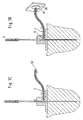
- Figure 1A shows the construction of a preferred catheter according to the present invention.
- the catheter comprises a hollow needle the distal part (10) of which is implanted in the tissue (2) of a patient.
- the hollow needle of figure 1 is manufactured from stainless steel and has an outer diameter of 500 ⁇ m, an inner diameter of 100 ⁇ m and a length of 7 mm. Plastics can for example also be used instead of stainless steel.
- a proximal region (11) with an enlarged inner cross section adjoins the distal part of the hollow needle.
- an outlet tube (14) attached to an outlet opening (13) of the hollow needle that is located slightly above the junction region between the implanted region and the proximal region (11).
- the catheter arrangement is attached by a disk-shaped holder (15) to the body surface.
- the underside of the holder (15) can be provided with an adhesive.
- a connecting element (16) above the holder (15) which ensures a fluid-tight coupling of the outlet tube (14) to the outlet opening (13) of the hollow needle (10, 11).
- FIG. 1A shows that body fluid, in particular interstitial fluid, enters the implanted region (10) of the hollow needle and is conveyed by capillary forces or by vacuum into the proximal part of the hollow needle (11).
- the implanted part (10) has one or several inlet openings (17). These can be located on the needle tip as well as in the wall region of the hollow needle located above this. The length of the implanted part and the position of the inlet openings can be used to determine from which depth body fluid is conveyed. It has proven to be advantageous to convey body fluids from depths of more than 1 mm.
- sample liquid from depths of more than 1 mm, preferably from a depth range of 3 to 10 mm.
- the body fluid rises in the hollow needle and fills the proximal part (11) of the hollow needle.
- This usually takes place solely by means of the capillary forces in the hollow needle.
- the interior region of the hollow needle that is to be wetted by sample liquid is made hydrophilic.
- this can for example be achieved by applying a hydrophilizing coating. If the capillary forces are not sufficient an underpressure may be applied to convey body fluid from the interior of the body.
- an air vent (12) is provided at the upper end of the hollow needle which allows air displaced by the body fluid to escape.
- the air vent is preferably made hydrophobic to prevent body fluid from escaping from the hollow needle.
- the air vent can for example be a plastic tube made from a hydrophobic polymer such as polyethylene. Another important function of the air vent is to limit evaporation from the hollow needle to avoid blockage of the system by dried up liquid.
- Figure 1B shows the arrangement of figure 1A in a filled state ready for the determination.
- firstly only the interior space of the hollow needle has been filled but not the connecting tube (14).
- Liquid is withdrawn from the filled state of figure 1B as shown in figures C and D.
- Application of an underpressure at the outlet opening (14') of the connecting tube (14) empties the upper widened part of the hollow needle (proximal part 11).
- the fluid forces in the system are adjusted such that only the hollow space of the needle above the outlet opening (13) is emptied.
- the system shown in figure 1 operates in a batch mode and the volume provided by one discharge can be adjusted by the volume in the upper needle region (11).
- liquid from an implanted needle can be drawn up directly onto a test zone by for example contacting the test zone with an outlet opening.
- Figure 2 shows a system for monitoring concentrations which has a measuring unit (101) and a disposable unit in which test zones are arranged in the form of a test element tape.
- the connecting tube (114) which can be coupled to the hollow needle as an alternative to the connecting tube (14) in figure 1 is shown on the front side of the disposable unit (121).
- the unit (121) is closed such that an underpressure relative to the outer space can be applied to its inner space via an underpressure connection (118).
- Two rollers are located in the interior space of the unit (121), of which the first, the dispenser roller (119) carries a reel of tape-shaped analytical agent. The tape is passed from the first roller (119) behind the outlet of the tube (114) and wound onto the second roller, the waste roller (120).
- the unit (121) has a rubber collar (122) in which a drive rod rotates which is driven by the measuring unit (101) and which winds the analytical tap onto the roller (120) in a step-wise manner.
- the measuring unit (101) is equipped with an optical head (102) which is inserted into a recess in the disposable unit (121).
- the optical head (102) has a light source for illuminating the analytical tape and a detector to record the reflected radiation.
- an optical window (103) is provided on the front side of the optical head (102).
- the measuring unit also has an electronic analytical unit to determine analyte concentrations based on the reflected radiation. The results that are determined can for example be shown directly on a display or they are passed onto a data processing unit (130) in order to be displayed or transmitted further.
- the measuring unit also has a connection (105) for the tube (118) and a pump connected to the connector which can be used to pump air out of the disposable unit (121).
- the measuring unit (101) additionally has a connector (104) for the rubber flange (122) and a drive mechanism for a drive rod that rotates in the flange.
- Underpressure is applied by the pump of the measuring unit to the disposable unit (121) such that body fluid that has collected in the catheter is sucked via the tube (114) into the unit (121) and passes onto the tape-like test element (analytical tape).
- the analytical optical system (102) is used to check whether the sample has been correctly applied to the test zone on the basis of the wetted spot.
- a reflection photometric analysis of the test zone is now carried out using the analytical optics (102) and the measurement result is converted into a concentration value for the analyte concentration.
- the application of fluid on the test zone can also be monitored and when a sufficient amount of fluid is detected, the contact between the test zone and fluid can be interrupted for example by releasing the underpressure.
- the contact between the test zone and fluid can be interrupted for example by releasing the underpressure.
- a fresh test zone is moved to the vicinity of the outlet opening of the tube (114).
- liquid can be conveyed by again applying an underpressure and can be taken up by the fresh analytical zone at the outlet position of the tube (114).
- Figure 3 shows a disposable unit (121') that is similar to the disposable unit shown in figure 2 .
- the hollow needle (110') that can be implanted in the body is already integrated into this disposable unit.
- the implantable region (110') is arranged perpendicular to the base surface (124') of the disposable unit.
- the hollow needle (110') is joined to the connecting tube (114') which is held by a holder (125').
- the tape-like test element (108') is guided past the outlet site of the connecting tube (114') to yield the sample application spot (140) at this position.
- the analytical tape is guided through rollers (126'). If one measurement is carried out every 5 minutes a 100 cm long analytical tape (108') enables the analyte concentration to be monitored over a period of about 24 hours. In order to prevent ageing of the analytical tape (108') during this period, a desiccant (127') can be provided in the disposable unit (121'). Also due to the ageing of the analytical material it is preferable to seal and store the disposable units (121/121') in a water-tight and vapour-tight manner before use. This can be achieved in a simple manner by sealing the disposable units after manufacture in a plastic laminate.
- Figure 4 shows a system for monitoring analyte concentrations which can for example be used in the field of emergency medicine.
- a catheter in a blood vessel in order to withdraw blood to monitor analyte concentrations or to administer medicines.
- a system can be coupled to it so that the analyte concentration can be monitored directly in the blood.
- a T-piece (201) can be provided for this via which blood is withdrawn using the withdrawal tube (114").
- the monitoring process is similar to that described in the previous figures. However, with the system shown withdrawal is made directly from the blood stream without the batch-wise filling and emptying of a hollow space of a predetermined volume as in figure 1 .
- Figure 5 shows an embodiment of a monitoring system that is integrated to a lesser degree.
- the unit (301) carried on the body comprises a catheter (310) that can be implanted in body tissue (2) which is held in a plate (315) that is attached to the body.
- a holder (302) for test elements with a receiving opening (303) is located above the catheter opening.
- the analytical zone (321) is placed above the catheter opening and body fluid emerging from the catheter wets the analytical zone.
- the test element is inserted manually into a conventional analytical instrument (400) and analysed there.
- the user can insert a second test element (320') into the opening (303) to wet the test zone (321').
- a second test element (320')
- the embodiment of figure 5 has an extremely simple construction and it is possible to use commercially available units for test elements and analytical instruments.
- a major advantage of the system of figure 5 compared to previous commercial systems is that the operator does not have to repeatedly pierce his body for the individual withdrawals of body fluid, but instead the unit (301) provides the necessary body fluid for the analyses as required.
Landscapes
- Health & Medical Sciences (AREA)
- Life Sciences & Earth Sciences (AREA)
- Physics & Mathematics (AREA)
- Engineering & Computer Science (AREA)
- Biomedical Technology (AREA)
- Molecular Biology (AREA)
- Biophysics (AREA)
- Pathology (AREA)
- General Health & Medical Sciences (AREA)
- Public Health (AREA)
- Medical Informatics (AREA)
- Surgery (AREA)
- Animal Behavior & Ethology (AREA)
- Heart & Thoracic Surgery (AREA)
- Optics & Photonics (AREA)
- Veterinary Medicine (AREA)
- Chemical & Material Sciences (AREA)
- Urology & Nephrology (AREA)
- Hematology (AREA)
- Emergency Medicine (AREA)
- Food Science & Technology (AREA)
- Medicinal Chemistry (AREA)
- Analytical Chemistry (AREA)
- Biochemistry (AREA)
- General Physics & Mathematics (AREA)
- Immunology (AREA)
- Measurement Of The Respiration, Hearing Ability, Form, And Blood Characteristics Of Living Organisms (AREA)
- Investigating Or Analysing Biological Materials (AREA)
Claims (25)
- Système pour surveiller la concentration d'analytes dans des liquides organiques, en particulier dans le liquide interstitiel, comprenanta) un cathéter possédant une région implantable (10, 110') et une ouverture de sortie (13) pour le retrait d'un liquide, en particulier d'un liquide organique ;b) une première et une deuxième zone analytique qui, après la mise en contact avec le liquide retiré, subissent un changement détectable lorsqu'un analyte est présent dans le liquide, lesdites première et deuxième zones analytiques étant jetables de telle sorte qu'une zone analytique qui a été utilisée une fois n'est plus réutilisée ;c) un dispositif pour la mise en contact de la première zone analytique avec le liquide provenant du cathéter et pour la mise en contact ultérieure de la deuxième zone analytique avec le liquide provenant du cathéter ;d) un dispositif analytique pour analyser les changements intervenus sur les zones analytiques, provoqués par le liquide contenant un ou plusieurs analytes dans le but de déterminer la concentration d'un analyte à surveiller ;la première et la deuxième zone analytique représentant des surfaces d'un élément de test en continu, de préférence d'un ruban (108').
- Système selon la revendication 1, dans lequel la mise en contact est mise en oeuvre en regroupant l'ouverture de sortie et la première et la deuxième zone analytique.
- Système selon la revendication 1, dans lequel les zones analytiques sont mises en contact en retirant des portions du liquide hors du cathéter pour les amener sur la première et sur la deuxième zone analytique au moyen d'une unité d'éjection.
- Système selon la revendication 1, dans lequel la première et la deuxième zone analytique représentent des objets séparés qui sont fixés à un support commun.
- Système selon la revendication 1, dans lequel on applique une pression négative sur l'ouverture de sortie dans le but de transporter du liquide.
- Système selon la revendication 1 ou 5, dans lequel le cathéter est conçu de telle sorte que du liquide ne sort pas de l'ouverture de sortie en l'absence de l'application d'une pression négative sur l'ouverture de sortie.
- Système selon la revendication 1, 5 ou 6, dans lequel le regroupement de la zone analytique et de l'ouverture de sortie est synchronisé avec l'application d'une pression négative de telle sorte que du liquide qui sort de l'ouverture de sortie est récupéré par la zone analytique.
- Système selon la revendication 1, dans lequel ledit dispositif analytique ou un dispositif d'application/détection supplémentaire détecte la présence de liquide ou la présence d'une quantité adéquate de liquide dans ou sur une zone analytique et interrompt la poursuite de la mise en contact de la zone analytique avec le liquide.
- Système selon la revendication 5, dans lequel ledit dispositif analytique ou un dispositif d'application/détection supplémentaire détecte la présence de liquide ou la présence d'une quantité adéquate de liquide dans ou sur une zone analytique et interrompt l'application de la pression négative sur l'ouverture de sortie.
- Système selon la revendication 1, comprenant un dispositif de contrôle qui synchronise le regroupement des première et deuxième zones analytiques avec l'ouverture de sortie.
- Système selon la revendication 1, 8 ou 9, dans lequel la quantité de liquide récupérée par une zone analytique est essentiellement égale ou supérieure au volume interne actif du cathéter.
- Système selon la revendication 1, dans lequel le cathéter est conçu pour rester implanté entre les mises en contact avec la première et avec la deuxième zone analytique.
- Système selon la revendication 1, dans lequel le système comprend une unité de transport pour le transport du système sur le corps et un magasin dans lequel les zones analytiques sont disposées et qui est conçu pour venir s'insérer dans l'unité de transport.
- Système selon la revendication 1, dans lequel la quantité de liquide récupérée par une zone analytique est inférieure à 100 nl et se situe de préférence dans la plage entre 10 et 50 nl.
- Système selon la revendication 1, dans lequel le dispositif analytique est conçu pour une analyse optique de zones analytiques.
- Procédé pour surveiller la concentration d'analytes dans des liquides organiques, en particulier dans le liquide interstitiel, comprenant les étapes- de la procuration d'une première et d'une deuxième zone analytique ;- du regroupement de la première zone analytique avec une ouverture de sortie d'un cathéter implanté à des fins de mise en contact de la première zone analytique avec un liquide, ladite première et ladite deuxième zone analytique étant jetables de telle sorte qu'une zone analytique qui a été utilisée une fois n'est plus réutilisée ;- de l'analyse du changement provoqué par le liquide contenant un ou plusieurs analytes dans la zone analytique dans le but de déterminer la concentration d'un analyte à surveiller ;la première et la deuxième zone analytique représentant des surfaces d'un élément de test en continu, de préférence d'un ruban (108').
- Procédé selon la revendication 16, dans lequel, après la mise en contact de la première zone analytique avec le liquide, la deuxième zone analytique et l'ouverture de sortie sont regroupées et mises en contact avec le liquide, et un changement dans la deuxième zone analytique, provoqué par le liquide contenant un ou plusieurs analytes, est analysé dans le but de déterminer la concentration d'un analyte à surveiller.
- Procédé selon la revendication 16 ou 17, dans lequel la zone analytique est déplacée à la main en direction de l'ouverture de sortie.
- Procédé selon la revendication 16 ou 17, dans lequel la zone analytique et l'ouverture de sortie sont regroupées au moyen d'un dispositif.
- Nécessaire pour surveiller la concentration d'analytes dans des liquides organiques, en particulier dans le liquide interstitiel, comprenant :- une unité de transport avec un cathéter comprenant une région implantable et une ouverture de sortie pour le retrait d'un liquide, en particulier d'un liquide organique ;- deux zones analytiques ou plus pour la mise en contact avec le liquide, qui subissent un changement détectable lorsqu'un analyte est présent dans le liquide, lesdites première et deuxième zone analytique étant jetables, de telle sorte qu'une zone analytique qui a été utilisée une fois n'est plus réutilisée ;- un dispositif analytique situé dans l'unité de transport ou présent séparément pour analyser les changements provoqués par le liquide contenant un ou plusieurs analytes sur les deux zones analytiques ou plus dans le but de déterminer la concentration d'un analyte à surveiller,la première et la deuxième zone analytique représentant des surfaces d'un élément de test en continu, de préférence d'un ruban (108').
- Nécessaire selon la revendication 20, possédant un dispositif pour regrouper une première zone analytique avec l'ouverture de sortie à des fins de mise en contact de la première zone analytique avec un liquide et pour le regroupement ultérieur de la deuxième zone analytique avec l'ouverture de sortie à des fins de mise en contact de la deuxième zone analytique avec un liquide.
- Magasin pour des zones analytiques, qui possède- une ouverture d'entrée pour un liquide ;- au moins une première et une deuxième zone analytique qui, après la mise en contact avec un liquide organique subissent un changement détectable lorsqu'un analyte est présent dans le liquide organique, lesdites première et deuxième zone analytique étant jetables, de telle sorte qu'une zone analytique qui a été utilisée une fois n'est plus réutilisée ; et- un dispositif pour amener la première et la deuxième zone analytique à proximité de l'ouverture d'entrée de telle sorte que du liquide pénétrant dans le magasin entre en contact avec la zone analytique respective ;la première et la deuxième zone analytique représentant des surfaces d'un élément de test en continu, de préférence d'un ruban (108').
- Magasin selon la revendication 22, qui est fermé de telle sorte que l'on peut générer une pression négative dans le magasin en aspirant de l'air à l'extérieur du magasin.
- Magasin selon la revendication 22 ou 23, qui possède une fenêtre optique.
- Magasin selon la revendication 22, qui possède une liaison par fluide à un cathéter pour retirer un liquide d'un corps.
Applications Claiming Priority (3)
| Application Number | Priority Date | Filing Date | Title |
|---|---|---|---|
| DE10105549 | 2001-02-06 | ||
| DE10105549A DE10105549A1 (de) | 2001-02-06 | 2001-02-06 | System zur Überwachung der Konzentration von Analyten in Körperflüssigkeiten |
| PCT/EP2002/001091 WO2002062210A1 (fr) | 2001-02-06 | 2002-02-02 | Systeme permettant de controler la concentration d'analytes dans des fluides corporels |
Publications (2)
| Publication Number | Publication Date |
|---|---|
| EP1359841A1 EP1359841A1 (fr) | 2003-11-12 |
| EP1359841B1 true EP1359841B1 (fr) | 2008-09-03 |
Family
ID=7673172
Family Applications (1)
| Application Number | Title | Priority Date | Filing Date |
|---|---|---|---|
| EP02711825A Expired - Lifetime EP1359841B1 (fr) | 2001-02-06 | 2002-02-02 | Systeme permettant de controler la concentration d'analytes dans des fluides corporels |
Country Status (9)
| Country | Link |
|---|---|
| US (1) | US7276027B2 (fr) |
| EP (1) | EP1359841B1 (fr) |
| JP (1) | JP3765794B2 (fr) |
| CN (2) | CN100553560C (fr) |
| AT (1) | ATE406834T1 (fr) |
| CA (1) | CA2435550C (fr) |
| DE (2) | DE10105549A1 (fr) |
| ES (1) | ES2312552T3 (fr) |
| WO (1) | WO2002062210A1 (fr) |
Cited By (1)
| Publication number | Priority date | Publication date | Assignee | Title |
|---|---|---|---|---|
| WO2013087573A3 (fr) * | 2011-12-12 | 2013-10-10 | sense2care GmbH | Dispositif pour l'analyse d'échantillons prélevés sur des patients |
Families Citing this family (122)
| Publication number | Priority date | Publication date | Assignee | Title |
|---|---|---|---|---|
| US6036924A (en) | 1997-12-04 | 2000-03-14 | Hewlett-Packard Company | Cassette of lancet cartridges for sampling blood |
| US6391005B1 (en) | 1998-03-30 | 2002-05-21 | Agilent Technologies, Inc. | Apparatus and method for penetration with shaft having a sensor for sensing penetration depth |
| US8641644B2 (en) | 2000-11-21 | 2014-02-04 | Sanofi-Aventis Deutschland Gmbh | Blood testing apparatus having a rotatable cartridge with multiple lancing elements and testing means |
| WO2002100274A1 (fr) | 2001-06-08 | 2002-12-19 | Hoffmann-La Roche Ag | Dispositif de prelevement de liquide corporel et cassette a support d'essai destinee a etre utilisee avec ledit dispositif |
| DE60239132D1 (de) | 2001-06-12 | 2011-03-24 | Pelikan Technologies Inc | Gerät zur erhöhung der erfolgsrate im hinblick auf die durch einen fingerstich erhaltene blutausbeute |
| AU2002320094A1 (en) | 2001-06-12 | 2002-12-23 | Pelikan Technologies, Inc. | Integrated blood sampling analysis system with multi-use sampling module |
| WO2002100252A2 (fr) | 2001-06-12 | 2002-12-19 | Pelikan Technologies, Inc. | Appareil de prelevement sanguin et procede connexe |
| AU2002315180A1 (en) | 2001-06-12 | 2002-12-23 | Pelikan Technologies, Inc. | Electric lancet actuator |
| US9427532B2 (en) | 2001-06-12 | 2016-08-30 | Sanofi-Aventis Deutschland Gmbh | Tissue penetration device |
| US9795747B2 (en) | 2010-06-02 | 2017-10-24 | Sanofi-Aventis Deutschland Gmbh | Methods and apparatus for lancet actuation |
| DE60234598D1 (de) | 2001-06-12 | 2010-01-14 | Pelikan Technologies Inc | Selbstoptimierende lanzettenvorrichtung mit adaptationsmittel für zeitliche schwankungen von hauteigenschaften |
| US7981056B2 (en) | 2002-04-19 | 2011-07-19 | Pelikan Technologies, Inc. | Methods and apparatus for lancet actuation |
| US7025774B2 (en) | 2001-06-12 | 2006-04-11 | Pelikan Technologies, Inc. | Tissue penetration device |
| US8337419B2 (en) | 2002-04-19 | 2012-12-25 | Sanofi-Aventis Deutschland Gmbh | Tissue penetration device |
| EP1404235A4 (fr) | 2001-06-12 | 2008-08-20 | Pelikan Technologies Inc | Procede et appareil pour un dispositif de lancement de lancette integre sur une cartouche de prelevement de sang |
| US9226699B2 (en) | 2002-04-19 | 2016-01-05 | Sanofi-Aventis Deutschland Gmbh | Body fluid sampling module with a continuous compression tissue interface surface |
| US7344894B2 (en) | 2001-10-16 | 2008-03-18 | Agilent Technologies, Inc. | Thermal regulation of fluidic samples within a diagnostic cartridge |
| US10022078B2 (en) | 2004-07-13 | 2018-07-17 | Dexcom, Inc. | Analyte sensor |
| US7297122B2 (en) | 2002-04-19 | 2007-11-20 | Pelikan Technologies, Inc. | Method and apparatus for penetrating tissue |
| US7901362B2 (en) | 2002-04-19 | 2011-03-08 | Pelikan Technologies, Inc. | Method and apparatus for penetrating tissue |
| US7175642B2 (en) | 2002-04-19 | 2007-02-13 | Pelikan Technologies, Inc. | Methods and apparatus for lancet actuation |
| US7491178B2 (en) | 2002-04-19 | 2009-02-17 | Pelikan Technologies, Inc. | Method and apparatus for penetrating tissue |
| US7892185B2 (en) | 2002-04-19 | 2011-02-22 | Pelikan Technologies, Inc. | Method and apparatus for body fluid sampling and analyte sensing |
| US8221334B2 (en) | 2002-04-19 | 2012-07-17 | Sanofi-Aventis Deutschland Gmbh | Method and apparatus for penetrating tissue |
| US8702624B2 (en) | 2006-09-29 | 2014-04-22 | Sanofi-Aventis Deutschland Gmbh | Analyte measurement device with a single shot actuator |
| US9795334B2 (en) | 2002-04-19 | 2017-10-24 | Sanofi-Aventis Deutschland Gmbh | Method and apparatus for penetrating tissue |
| US7198606B2 (en) | 2002-04-19 | 2007-04-03 | Pelikan Technologies, Inc. | Method and apparatus for a multi-use body fluid sampling device with analyte sensing |
| US7374544B2 (en) | 2002-04-19 | 2008-05-20 | Pelikan Technologies, Inc. | Method and apparatus for penetrating tissue |
| US7524293B2 (en) | 2002-04-19 | 2009-04-28 | Pelikan Technologies, Inc. | Method and apparatus for penetrating tissue |
| US7909778B2 (en) | 2002-04-19 | 2011-03-22 | Pelikan Technologies, Inc. | Method and apparatus for penetrating tissue |
| US7232451B2 (en) | 2002-04-19 | 2007-06-19 | Pelikan Technologies, Inc. | Method and apparatus for penetrating tissue |
| US7410468B2 (en) | 2002-04-19 | 2008-08-12 | Pelikan Technologies, Inc. | Method and apparatus for penetrating tissue |
| US7674232B2 (en) | 2002-04-19 | 2010-03-09 | Pelikan Technologies, Inc. | Method and apparatus for penetrating tissue |
| US7717863B2 (en) | 2002-04-19 | 2010-05-18 | Pelikan Technologies, Inc. | Method and apparatus for penetrating tissue |
| US7258693B2 (en) | 2002-04-19 | 2007-08-21 | Pelikan Technologies, Inc. | Device and method for variable speed lancet |
| US8784335B2 (en) | 2002-04-19 | 2014-07-22 | Sanofi-Aventis Deutschland Gmbh | Body fluid sampling device with a capacitive sensor |
| US7547287B2 (en) | 2002-04-19 | 2009-06-16 | Pelikan Technologies, Inc. | Method and apparatus for penetrating tissue |
| US7485128B2 (en) | 2002-04-19 | 2009-02-03 | Pelikan Technologies, Inc. | Method and apparatus for penetrating tissue |
| US9314194B2 (en) | 2002-04-19 | 2016-04-19 | Sanofi-Aventis Deutschland Gmbh | Tissue penetration device |
| US7371247B2 (en) | 2002-04-19 | 2008-05-13 | Pelikan Technologies, Inc | Method and apparatus for penetrating tissue |
| US7244265B2 (en) | 2002-04-19 | 2007-07-17 | Pelikan Technologies, Inc. | Method and apparatus for penetrating tissue |
| US7648468B2 (en) | 2002-04-19 | 2010-01-19 | Pelikon Technologies, Inc. | Method and apparatus for penetrating tissue |
| US9248267B2 (en) | 2002-04-19 | 2016-02-02 | Sanofi-Aventis Deustchland Gmbh | Tissue penetration device |
| US7892183B2 (en) | 2002-04-19 | 2011-02-22 | Pelikan Technologies, Inc. | Method and apparatus for body fluid sampling and analyte sensing |
| US8267870B2 (en) | 2002-04-19 | 2012-09-18 | Sanofi-Aventis Deutschland Gmbh | Method and apparatus for body fluid sampling with hybrid actuation |
| US8360992B2 (en) | 2002-04-19 | 2013-01-29 | Sanofi-Aventis Deutschland Gmbh | Method and apparatus for penetrating tissue |
| US7291117B2 (en) | 2002-04-19 | 2007-11-06 | Pelikan Technologies, Inc. | Method and apparatus for penetrating tissue |
| US7563232B2 (en) | 2002-04-19 | 2009-07-21 | Pelikan Technologies, Inc. | Method and apparatus for penetrating tissue |
| US7141058B2 (en) | 2002-04-19 | 2006-11-28 | Pelikan Technologies, Inc. | Method and apparatus for a body fluid sampling device using illumination |
| US8579831B2 (en) | 2002-04-19 | 2013-11-12 | Sanofi-Aventis Deutschland Gmbh | Method and apparatus for penetrating tissue |
| US7229458B2 (en) | 2002-04-19 | 2007-06-12 | Pelikan Technologies, Inc. | Method and apparatus for penetrating tissue |
| US7331931B2 (en) | 2002-04-19 | 2008-02-19 | Pelikan Technologies, Inc. | Method and apparatus for penetrating tissue |
| US7976476B2 (en) | 2002-04-19 | 2011-07-12 | Pelikan Technologies, Inc. | Device and method for variable speed lancet |
| EP1424040A1 (fr) * | 2002-11-26 | 2004-06-02 | Roche Diagnostics GmbH | Dispositif de test pour fluides corporels |
| US7731900B2 (en) | 2002-11-26 | 2010-06-08 | Roche Diagnostics Operations, Inc. | Body fluid testing device |
| ES2522972T3 (es) | 2002-12-23 | 2014-11-19 | F.Hoffmann-La Roche Ag | Dispositivo para ensayar fluidos corporales |
| US7582258B2 (en) | 2002-12-23 | 2009-09-01 | Roche Diagnostics Operations, Inc. | Body fluid testing device |
| EP1479344A1 (fr) | 2003-05-22 | 2004-11-24 | Roche Diagnostics GmbH | Surveillance directe de composition de fluide interstitiel |
| US7481777B2 (en) * | 2006-01-05 | 2009-01-27 | Roche Diagnostics Operations, Inc. | Lancet integrated test element tape dispenser |
| US8574895B2 (en) | 2002-12-30 | 2013-11-05 | Sanofi-Aventis Deutschland Gmbh | Method and apparatus using optical techniques to measure analyte levels |
| DE602004028463D1 (de) | 2003-05-30 | 2010-09-16 | Pelikan Technologies Inc | Verfahren und vorrichtung zur injektion von flüssigkeit |
| WO2004107964A2 (fr) | 2003-06-06 | 2004-12-16 | Pelikan Technologies, Inc. | Procede et appareil d'echantillonnage de fluides anatomiques et d'examen de l'analysat |
| WO2006001797A1 (fr) | 2004-06-14 | 2006-01-05 | Pelikan Technologies, Inc. | Element penetrant peu douloureux |
| US7604592B2 (en) | 2003-06-13 | 2009-10-20 | Pelikan Technologies, Inc. | Method and apparatus for a point of care device |
| US7920906B2 (en) | 2005-03-10 | 2011-04-05 | Dexcom, Inc. | System and methods for processing analyte sensor data for sensor calibration |
| US8282576B2 (en) | 2003-09-29 | 2012-10-09 | Sanofi-Aventis Deutschland Gmbh | Method and apparatus for an improved sample capture device |
| EP1680014A4 (fr) | 2003-10-14 | 2009-01-21 | Pelikan Technologies Inc | Procede et appareil fournissant une interface-utilisateur variable |
| US9247900B2 (en) | 2004-07-13 | 2016-02-02 | Dexcom, Inc. | Analyte sensor |
| US20050137471A1 (en) * | 2003-12-18 | 2005-06-23 | Hans-Peter Haar | Continuous glucose monitoring device |
| EP1706026B1 (fr) | 2003-12-31 | 2017-03-01 | Sanofi-Aventis Deutschland GmbH | Procédé et appareil permettant d'améliorer le flux fluidique et le prélèvement d'échantillons |
| US7822454B1 (en) | 2005-01-03 | 2010-10-26 | Pelikan Technologies, Inc. | Fluid sampling device with improved analyte detecting member configuration |
| PL2705792T3 (pl) | 2004-03-06 | 2015-10-30 | Hoffmann La Roche | Urządzenie do pobierania próbki płynu ustrojowego |
| US7819822B2 (en) | 2004-03-06 | 2010-10-26 | Roche Diagnostics Operations, Inc. | Body fluid sampling device |
| WO2006011062A2 (fr) | 2004-05-20 | 2006-02-02 | Albatros Technologies Gmbh & Co. Kg | Hydrogel imprimable pour biocapteurs |
| WO2005120365A1 (fr) | 2004-06-03 | 2005-12-22 | Pelikan Technologies, Inc. | Procede et appareil pour la fabrication d'un dispositif d'echantillonnage de liquides |
| US9775553B2 (en) | 2004-06-03 | 2017-10-03 | Sanofi-Aventis Deutschland Gmbh | Method and apparatus for a fluid sampling device |
| US8989833B2 (en) | 2004-07-13 | 2015-03-24 | Dexcom, Inc. | Transcutaneous analyte sensor |
| US8652831B2 (en) | 2004-12-30 | 2014-02-18 | Sanofi-Aventis Deutschland Gmbh | Method and apparatus for analyte measurement test time |
| WO2006076930A1 (fr) * | 2005-01-21 | 2006-07-27 | Roche Diagnostics Gmbh | Dispositif de surveillance en continu du glucose |
| DE102005007901A1 (de) * | 2005-02-21 | 2006-08-31 | Roche Diagnostics Gmbh | Katheter mit Mikrokanälen für die Überwachung der Konzentration eines Analyten in einer Körperflüssigkeit |
| WO2006105146A2 (fr) * | 2005-03-29 | 2006-10-05 | Arkal Medical, Inc. | Dispositifs, systemes, procedes et outils pour la surveillance continue du glucose |
| US7909773B2 (en) * | 2005-06-03 | 2011-03-22 | Tyco Healthcare Group Lp | Post-operative bacteria test strip spool and method |
| US8202249B2 (en) * | 2005-09-20 | 2012-06-19 | Panasonic Corporation | Injection device with puncture function, method for controlling injection device with puncture function, chemical solution administration device, and method for controlling chemical solution administration device |
| US8388905B2 (en) * | 2006-03-13 | 2013-03-05 | Nipro Diagnostics, Inc. | Method and apparatus for coding diagnostic meters |
| US8388906B2 (en) * | 2006-03-13 | 2013-03-05 | Nipro Diagnostics, Inc. | Apparatus for dispensing test strips |
| US8940246B2 (en) | 2006-03-13 | 2015-01-27 | Nipro Diagnostics, Inc. | Method and apparatus for coding diagnostic meters |
| US11559810B2 (en) | 2006-03-13 | 2023-01-24 | Trividia Health, Inc. | Method and apparatus for coding diagnostic meters |
| US7809441B2 (en) | 2006-05-17 | 2010-10-05 | Cardiac Pacemakers, Inc. | Implantable medical device with chemical sensor and related methods |
| PL1873521T3 (pl) * | 2006-06-27 | 2012-02-29 | Hoffmann La Roche | Diagnostyczna kaseta z taśmą |
| US20080058726A1 (en) * | 2006-08-30 | 2008-03-06 | Arvind Jina | Methods and Apparatus Incorporating a Surface Penetration Device |
| US7833201B2 (en) | 2006-09-29 | 2010-11-16 | Tyco Healthcare Group Lp | Flashback chamber visual enhancement |
| WO2008089766A1 (fr) * | 2007-01-26 | 2008-07-31 | Diramo A/S | Système d'analyse équipé d'une unité d'analyse à distance |
| US20100268043A1 (en) * | 2007-11-07 | 2010-10-21 | Ofer Yodfat | Device and Method for Preventing Diabetic Complications |
| US8986253B2 (en) | 2008-01-25 | 2015-03-24 | Tandem Diabetes Care, Inc. | Two chamber pumps and related methods |
| US7766846B2 (en) | 2008-01-28 | 2010-08-03 | Roche Diagnostics Operations, Inc. | Rapid blood expression and sampling |
| US8229535B2 (en) | 2008-02-21 | 2012-07-24 | Dexcom, Inc. | Systems and methods for blood glucose monitoring and alert delivery |
| WO2009126900A1 (fr) | 2008-04-11 | 2009-10-15 | Pelikan Technologies, Inc. | Procédé et appareil pour dispositif de détection d’analyte |
| EP2135546B1 (fr) * | 2008-06-18 | 2014-09-10 | Roche Diagnostics GmbH | Cassette à bande pour un appareil médical portable |
| US8465977B2 (en) | 2008-07-22 | 2013-06-18 | Roche Diagnostics Operations, Inc. | Method and apparatus for lighted test strip |
| US8408421B2 (en) | 2008-09-16 | 2013-04-02 | Tandem Diabetes Care, Inc. | Flow regulating stopcocks and related methods |
| AU2009293019A1 (en) | 2008-09-19 | 2010-03-25 | Tandem Diabetes Care Inc. | Solute concentration measurement device and related methods |
| US9375169B2 (en) | 2009-01-30 | 2016-06-28 | Sanofi-Aventis Deutschland Gmbh | Cam drive for managing disposable penetrating member actions with a single motor and motor and control system |
| US20110027458A1 (en) | 2009-07-02 | 2011-02-03 | Dexcom, Inc. | Continuous analyte sensors and methods of making same |
| EP3284494A1 (fr) | 2009-07-30 | 2018-02-21 | Tandem Diabetes Care, Inc. | Système de pompe à perfusion portable |
| US8965476B2 (en) | 2010-04-16 | 2015-02-24 | Sanofi-Aventis Deutschland Gmbh | Tissue penetration device |
| US20130280696A1 (en) * | 2012-04-23 | 2013-10-24 | Elliott Millenson | Devices and methods for detecting analyte in bodily fluid |
| US9180242B2 (en) | 2012-05-17 | 2015-11-10 | Tandem Diabetes Care, Inc. | Methods and devices for multiple fluid transfer |
| US9555186B2 (en) | 2012-06-05 | 2017-01-31 | Tandem Diabetes Care, Inc. | Infusion pump system with disposable cartridge having pressure venting and pressure feedback |
| US20150338408A1 (en) * | 2012-11-14 | 2015-11-26 | University Of Utah Research Foundation | Single step calibration curve through sample convection |
| US9173998B2 (en) | 2013-03-14 | 2015-11-03 | Tandem Diabetes Care, Inc. | System and method for detecting occlusions in an infusion pump |
| US10036709B2 (en) | 2014-05-20 | 2018-07-31 | Roche Diabetes Care, Inc. | BG meter illuminated test strip |
| US10716500B2 (en) | 2015-06-29 | 2020-07-21 | Cardiac Pacemakers, Inc. | Systems and methods for normalization of chemical sensor data based on fluid state changes |
| CN108968976B (zh) | 2017-05-31 | 2022-09-13 | 心脏起搏器股份公司 | 具有化学传感器的植入式医疗设备 |
| WO2019023093A1 (fr) | 2017-07-26 | 2019-01-31 | Cardiac Pacemakers, Inc. | Systèmes et procédés de désambiguïsation de posture |
| CN109381195B (zh) | 2017-08-10 | 2023-01-10 | 心脏起搏器股份公司 | 包括电解质传感器融合的系统和方法 |
| CN109419515B (zh) | 2017-08-23 | 2023-03-24 | 心脏起搏器股份公司 | 具有分级激活的可植入化学传感器 |
| CN109864746B (zh) | 2017-12-01 | 2023-09-29 | 心脏起搏器股份公司 | 用于医学装置的多模式分析物传感器 |
| CN109864747B (zh) | 2017-12-05 | 2023-08-25 | 心脏起搏器股份公司 | 多模式分析物传感器光电子接口 |
| US11101872B2 (en) * | 2019-09-23 | 2021-08-24 | Amphenol Antenna Solutions, Inc. | High gain single lens repeater platform |
| US12551145B2 (en) | 2020-10-29 | 2026-02-17 | Cardiac Pacemakers, Inc. | Integrated thermo-photonic chemical sensor |
| CN114602321B (zh) * | 2022-02-16 | 2022-10-21 | 中国科学院水生生物研究所 | 一种可用于环境dna采样的弹匣式滤膜更换系统 |
| CN114577524B (zh) * | 2022-02-21 | 2024-03-12 | 中国科学院水生生物研究所 | 用于环境dna采样的弹匣式滤膜更换装置及系统 |
Citations (1)
| Publication number | Priority date | Publication date | Assignee | Title |
|---|---|---|---|---|
| US5902253A (en) * | 1996-06-11 | 1999-05-11 | Siemens-Elema Ab | Apparatus for analyzing body fluids |
Family Cites Families (44)
| Publication number | Priority date | Publication date | Assignee | Title |
|---|---|---|---|---|
| US1458958A (en) * | 1921-10-21 | 1923-06-19 | Ralph F Schneider | Bleeding apparatus |
| US3651807A (en) | 1970-02-19 | 1972-03-28 | James A Huggins | Detachable, hollow guide needle |
| US3659587A (en) * | 1970-06-30 | 1972-05-02 | Affiliated Hospital Prod | Valved connector arrangement |
| US4199261A (en) | 1976-12-29 | 1980-04-22 | Smith-Kettlewell Eye Research Foundation | Optical intensity meter |
| DE2734247C2 (de) | 1977-07-29 | 1984-07-19 | Fresenius AG, 6380 Bad Homburg | Vorrichtung zur fortlaufenden chemischen Analyse im lebenden Körper |
| US4218421A (en) | 1978-08-18 | 1980-08-19 | Honeywell Inc. | Disposable container for a continuous band of test strips |
| US4336544A (en) | 1980-08-18 | 1982-06-22 | Hewlett-Packard Company | Method and apparatus for drop-on-demand ink jet printing |
| DE3112762A1 (de) | 1981-03-31 | 1983-01-13 | Jürgen Dr.med. 8700 Würzburg Schrezenmeir | Doppellumen-blutentnahme-einfachlumen-infusions-subclavia-katheterset |
| DE3278024D1 (en) | 1981-09-08 | 1988-02-25 | Eastman Kodak Co | Method and apparatus for detecting sample fluid |
| CA1254091A (fr) | 1984-09-28 | 1989-05-16 | Vladimir Feingold | Systeme implantable pour la perfusion de medicaments |
| DE3617161A1 (de) | 1986-05-22 | 1987-11-26 | Boehringer Mannheim Gmbh | System zur bestimmung der konzentration von bestandteilen von koerperfluessigkeiten |
| US4935346A (en) | 1986-08-13 | 1990-06-19 | Lifescan, Inc. | Minimum procedure system for the determination of analytes |
| US4989606A (en) * | 1987-01-30 | 1991-02-05 | Minnesota Mining And Manufactoring Company | Intravascular blood gas sensing system |
| US4777953A (en) | 1987-02-25 | 1988-10-18 | Ash Medical Systems, Inc. | Capillary filtration and collection method for long-term monitoring of blood constituents |
| US4832034A (en) | 1987-04-09 | 1989-05-23 | Pizziconi Vincent B | Method and apparatus for withdrawing, collecting and biosensing chemical constituents from complex fluids |
| NL8702370A (nl) | 1987-10-05 | 1989-05-01 | Groningen Science Park | Werkwijze en stelsel voor glucosebepaling en daarvoor bruikbaar meetcelsamenstel. |
| US4957489A (en) | 1988-10-19 | 1990-09-18 | Critikon, Inc. | Through the needle catheter insertion device and technique |
| EP0373413A1 (fr) | 1988-12-13 | 1990-06-20 | Daikin Industries, Limited | Appareil d'assistance, appareil de test et méthode pour mesurer la concentration d'une substance dans un liquide |
| US5035704A (en) * | 1989-03-07 | 1991-07-30 | Lambert Robert D | Blood sampling mechanism |
| US5114350A (en) | 1989-03-08 | 1992-05-19 | Cholestech Corporation | Controlled-volume assay apparatus |
| DE3908123A1 (de) * | 1989-03-13 | 1990-09-20 | Schulz Peter | Analysegeraet |
| IT1231916B (it) | 1989-05-29 | 1992-01-15 | Ampliscientifica S R L | Pancreas artificiale indossabile |
| AU634863B2 (en) | 1989-12-15 | 1993-03-04 | Roche Diagnostics Operations Inc. | Redox mediator reagent and biosensor |
| WO1991016416A1 (fr) | 1990-04-26 | 1991-10-31 | Markwell Medical Institute, Inc. | Moniteur de glycemie portable |
| US5368029A (en) | 1992-04-16 | 1994-11-29 | Holcombe; David A. | Integral catheter and blood tester |
| US5335658A (en) | 1992-06-29 | 1994-08-09 | Minnesota Mining And Manufacturing Company | Intravascular blood parameter sensing system |
| DE4326339A1 (de) * | 1993-08-05 | 1995-02-09 | Boehringer Mannheim Gmbh | System zur Analyse von Probenflüssigkeiten |
| US5582184A (en) | 1993-10-13 | 1996-12-10 | Integ Incorporated | Interstitial fluid collection and constituent measurement |
| SE502394C2 (sv) | 1994-02-04 | 1995-10-16 | Cma Microdialysis Holding Ab | Dialysprobskombination jämte mikrodialysprob och kanylrör för kombinationen |
| ATE208640T1 (de) | 1994-08-25 | 2001-11-15 | Baxter Int | Geschlossene blutprobensystemvorrichtung |
| US5496300A (en) | 1994-08-26 | 1996-03-05 | Hirsch; Michael P. | Coupling device for a leg urinal |
| US5879367A (en) | 1995-09-08 | 1999-03-09 | Integ, Inc. | Enhanced interstitial fluid collection |
| US5682233A (en) * | 1995-09-08 | 1997-10-28 | Integ, Inc. | Interstitial fluid sampler |
| US5741233A (en) | 1995-10-20 | 1998-04-21 | Tfx Medical, Incorporated | Introducer device and methods of use thereof |
| DE19629656A1 (de) | 1996-07-23 | 1998-01-29 | Boehringer Mannheim Gmbh | Diagnostischer Testträger mit mehrschichtigem Testfeld und Verfahren zur Bestimmung von Analyt mit dessen Hilfe |
| US5947911A (en) * | 1997-01-09 | 1999-09-07 | Via Medical Corporation | Method and apparatus for reducing purge volume in a blood chemistry monitoring system |
| JP2985816B2 (ja) * | 1997-02-04 | 1999-12-06 | 日本電気株式会社 | 液体採取装置 |
| US6029919A (en) | 1997-11-24 | 2000-02-29 | Rousseau; Victor | Cattle feed mixer with hay chopper |
| JPH11183474A (ja) | 1997-12-24 | 1999-07-09 | Terumo Corp | 試験紙および成分測定用チップ |
| DE19819407A1 (de) * | 1998-04-30 | 1999-11-11 | Hendrik Priebs | Teststreifenbehälter für Messgeräte, die mit Einwegteststreifen arbeiten |
| WO2000013580A1 (fr) | 1998-09-11 | 2000-03-16 | Amira Medical | Dispositif d'evaluation d'un analysat dans un fluide anatomique, integre a une pompe a insuline |
| DE19846466A1 (de) * | 1998-10-08 | 2000-04-27 | Ghs Gesundheits Service Ag | Analyseverfahren zur simultanen Bestimmung von Parametern aus unterschiedlichen Medien |
| DE19848112C2 (de) * | 1998-10-19 | 2001-12-13 | Meinhard Knoll | Minimalinvasives Sensorsystem |
| WO2002100274A1 (fr) * | 2001-06-08 | 2002-12-19 | Hoffmann-La Roche Ag | Dispositif de prelevement de liquide corporel et cassette a support d'essai destinee a etre utilisee avec ledit dispositif |
-
2001
- 2001-02-06 DE DE10105549A patent/DE10105549A1/de not_active Ceased
-
2002
- 2002-02-02 CA CA002435550A patent/CA2435550C/fr not_active Expired - Fee Related
- 2002-02-02 WO PCT/EP2002/001091 patent/WO2002062210A1/fr not_active Ceased
- 2002-02-02 CN CNB2007101386856A patent/CN100553560C/zh not_active Expired - Fee Related
- 2002-02-02 CN CNB028046153A patent/CN100405968C/zh not_active Expired - Fee Related
- 2002-02-02 US US10/467,592 patent/US7276027B2/en not_active Expired - Fee Related
- 2002-02-02 AT AT02711825T patent/ATE406834T1/de not_active IP Right Cessation
- 2002-02-02 ES ES02711825T patent/ES2312552T3/es not_active Expired - Lifetime
- 2002-02-02 EP EP02711825A patent/EP1359841B1/fr not_active Expired - Lifetime
- 2002-02-02 DE DE60228684T patent/DE60228684D1/de not_active Expired - Lifetime
- 2002-02-02 JP JP2002562220A patent/JP3765794B2/ja not_active Expired - Fee Related
Patent Citations (1)
| Publication number | Priority date | Publication date | Assignee | Title |
|---|---|---|---|---|
| US5902253A (en) * | 1996-06-11 | 1999-05-11 | Siemens-Elema Ab | Apparatus for analyzing body fluids |
Cited By (1)
| Publication number | Priority date | Publication date | Assignee | Title |
|---|---|---|---|---|
| WO2013087573A3 (fr) * | 2011-12-12 | 2013-10-10 | sense2care GmbH | Dispositif pour l'analyse d'échantillons prélevés sur des patients |
Also Published As
| Publication number | Publication date |
|---|---|
| CN1496236A (zh) | 2004-05-12 |
| DE60228684D1 (de) | 2008-10-16 |
| CN101112312A (zh) | 2008-01-30 |
| JP3765794B2 (ja) | 2006-04-12 |
| CA2435550C (fr) | 2009-09-29 |
| EP1359841A1 (fr) | 2003-11-12 |
| ES2312552T3 (es) | 2009-03-01 |
| JP2004521683A (ja) | 2004-07-22 |
| CN100553560C (zh) | 2009-10-28 |
| US20040249311A1 (en) | 2004-12-09 |
| CN100405968C (zh) | 2008-07-30 |
| US7276027B2 (en) | 2007-10-02 |
| HK1063595A1 (zh) | 2005-01-07 |
| CA2435550A1 (fr) | 2002-08-15 |
| DE10105549A1 (de) | 2002-08-29 |
| WO2002062210A1 (fr) | 2002-08-15 |
| ATE406834T1 (de) | 2008-09-15 |
Similar Documents
| Publication | Publication Date | Title |
|---|---|---|
| EP1359841B1 (fr) | Systeme permettant de controler la concentration d'analytes dans des fluides corporels | |
| US20080214909A1 (en) | Catheter With Microchannels For Monitoring The Concentration Of An Analyte In A Bodily Fluid | |
| US8092385B2 (en) | Fluid access interface | |
| CA2424288C (fr) | Dispositif et procede de prelevement de fluide interstitiel d'un patient pour tests diagnostiques | |
| US7819822B2 (en) | Body fluid sampling device | |
| US6045541A (en) | Device for taking up fluid | |
| CA2837991C (fr) | Dispositif pour echantillonner du liquide organique | |
| US20070129618A1 (en) | Blood parameter testing system | |
| US20080009767A1 (en) | System for withdrawing small amounts of body fluid | |
| JP2008515483A (ja) | 血液監視システム | |
| EP1578272A1 (fr) | Dispositif de test de liquide biologique | |
| EP1928299B1 (fr) | Dispositifs de transport d'echantillons de fluide | |
| HK1063595B (en) | System and method for monitoring the concentration of analytes in body fluids | |
| HK1116648A (en) | System, for monitoring the concentration of analytes in body fluids | |
| KR100848529B1 (ko) | 체액 샘플링 장치 | |
| WO2006076930A1 (fr) | Dispositif de surveillance en continu du glucose |
Legal Events
| Date | Code | Title | Description |
|---|---|---|---|
| PUAI | Public reference made under article 153(3) epc to a published international application that has entered the european phase |
Free format text: ORIGINAL CODE: 0009012 |
|
| 17P | Request for examination filed |
Effective date: 20030908 |
|
| AK | Designated contracting states |
Kind code of ref document: A1 Designated state(s): AT BE CH CY DE DK ES FI FR GB GR IE IT LI LU MC NL PT SE TR |
|
| AX | Request for extension of the european patent |
Extension state: AL LT LV MK RO SI |
|
| 17Q | First examination report despatched |
Effective date: 20070116 |
|
| GRAP | Despatch of communication of intention to grant a patent |
Free format text: ORIGINAL CODE: EPIDOSNIGR1 |
|
| RTI1 | Title (correction) |
Free format text: SYSTEM FOR MONITORING THE CONCENTRATION OF ANALYTES IN BODY FLUIDS |
|
| GRAS | Grant fee paid |
Free format text: ORIGINAL CODE: EPIDOSNIGR3 |
|
| GRAA | (expected) grant |
Free format text: ORIGINAL CODE: 0009210 |
|
| AK | Designated contracting states |
Kind code of ref document: B1 Designated state(s): AT BE CH CY DE DK ES FI FR GB GR IE IT LI LU MC NL PT SE TR |
|
| REG | Reference to a national code |
Ref country code: GB Ref legal event code: FG4D |
|
| REG | Reference to a national code |
Ref country code: CH Ref legal event code: EP |
|
| REG | Reference to a national code |
Ref country code: IE Ref legal event code: FG4D |
|
| REF | Corresponds to: |
Ref document number: 60228684 Country of ref document: DE Date of ref document: 20081016 Kind code of ref document: P |
|
| PG25 | Lapsed in a contracting state [announced via postgrant information from national office to epo] |
Ref country code: AT Free format text: LAPSE BECAUSE OF FAILURE TO SUBMIT A TRANSLATION OF THE DESCRIPTION OR TO PAY THE FEE WITHIN THE PRESCRIBED TIME-LIMIT Effective date: 20080903 Ref country code: FI Free format text: LAPSE BECAUSE OF FAILURE TO SUBMIT A TRANSLATION OF THE DESCRIPTION OR TO PAY THE FEE WITHIN THE PRESCRIBED TIME-LIMIT Effective date: 20080903 |
|
| REG | Reference to a national code |
Ref country code: ES Ref legal event code: FG2A Ref document number: 2312552 Country of ref document: ES Kind code of ref document: T3 |
|
| PG25 | Lapsed in a contracting state [announced via postgrant information from national office to epo] |
Ref country code: BE Free format text: LAPSE BECAUSE OF FAILURE TO SUBMIT A TRANSLATION OF THE DESCRIPTION OR TO PAY THE FEE WITHIN THE PRESCRIBED TIME-LIMIT Effective date: 20080903 |
|
| PG25 | Lapsed in a contracting state [announced via postgrant information from national office to epo] |
Ref country code: PT Free format text: LAPSE BECAUSE OF FAILURE TO SUBMIT A TRANSLATION OF THE DESCRIPTION OR TO PAY THE FEE WITHIN THE PRESCRIBED TIME-LIMIT Effective date: 20090203 |
|
| PLBE | No opposition filed within time limit |
Free format text: ORIGINAL CODE: 0009261 |
|
| STAA | Information on the status of an ep patent application or granted ep patent |
Free format text: STATUS: NO OPPOSITION FILED WITHIN TIME LIMIT |
|
| PG25 | Lapsed in a contracting state [announced via postgrant information from national office to epo] |
Ref country code: DK Free format text: LAPSE BECAUSE OF FAILURE TO SUBMIT A TRANSLATION OF THE DESCRIPTION OR TO PAY THE FEE WITHIN THE PRESCRIBED TIME-LIMIT Effective date: 20080903 |
|
| 26N | No opposition filed |
Effective date: 20090604 |
|
| PG25 | Lapsed in a contracting state [announced via postgrant information from national office to epo] |
Ref country code: MC Free format text: LAPSE BECAUSE OF NON-PAYMENT OF DUE FEES Effective date: 20090228 |
|
| PG25 | Lapsed in a contracting state [announced via postgrant information from national office to epo] |
Ref country code: IE Free format text: LAPSE BECAUSE OF NON-PAYMENT OF DUE FEES Effective date: 20090202 Ref country code: SE Free format text: LAPSE BECAUSE OF FAILURE TO SUBMIT A TRANSLATION OF THE DESCRIPTION OR TO PAY THE FEE WITHIN THE PRESCRIBED TIME-LIMIT Effective date: 20081203 |
|
| PG25 | Lapsed in a contracting state [announced via postgrant information from national office to epo] |
Ref country code: GR Free format text: LAPSE BECAUSE OF FAILURE TO SUBMIT A TRANSLATION OF THE DESCRIPTION OR TO PAY THE FEE WITHIN THE PRESCRIBED TIME-LIMIT Effective date: 20081204 |
|
| PG25 | Lapsed in a contracting state [announced via postgrant information from national office to epo] |
Ref country code: LU Free format text: LAPSE BECAUSE OF NON-PAYMENT OF DUE FEES Effective date: 20090202 |
|
| PG25 | Lapsed in a contracting state [announced via postgrant information from national office to epo] |
Ref country code: TR Free format text: LAPSE BECAUSE OF FAILURE TO SUBMIT A TRANSLATION OF THE DESCRIPTION OR TO PAY THE FEE WITHIN THE PRESCRIBED TIME-LIMIT Effective date: 20080903 |
|
| PG25 | Lapsed in a contracting state [announced via postgrant information from national office to epo] |
Ref country code: CY Free format text: LAPSE BECAUSE OF FAILURE TO SUBMIT A TRANSLATION OF THE DESCRIPTION OR TO PAY THE FEE WITHIN THE PRESCRIBED TIME-LIMIT Effective date: 20080903 |
|
| PGFP | Annual fee paid to national office [announced via postgrant information from national office to epo] |
Ref country code: IT Payment date: 20120216 Year of fee payment: 11 |
|
| PGFP | Annual fee paid to national office [announced via postgrant information from national office to epo] |
Ref country code: ES Payment date: 20130219 Year of fee payment: 12 Ref country code: GB Payment date: 20130125 Year of fee payment: 12 Ref country code: DE Payment date: 20130228 Year of fee payment: 12 Ref country code: FR Payment date: 20130218 Year of fee payment: 12 |
|
| PGFP | Annual fee paid to national office [announced via postgrant information from national office to epo] |
Ref country code: NL Payment date: 20130212 Year of fee payment: 12 |
|
| PGFP | Annual fee paid to national office [announced via postgrant information from national office to epo] |
Ref country code: CH Payment date: 20140127 Year of fee payment: 13 |
|
| REG | Reference to a national code |
Ref country code: DE Ref legal event code: R119 Ref document number: 60228684 Country of ref document: DE |
|
| REG | Reference to a national code |
Ref country code: NL Ref legal event code: V1 Effective date: 20140901 |
|
| GBPC | Gb: european patent ceased through non-payment of renewal fee |
Effective date: 20140202 |
|
| PG25 | Lapsed in a contracting state [announced via postgrant information from national office to epo] |
Ref country code: NL Free format text: LAPSE BECAUSE OF NON-PAYMENT OF DUE FEES Effective date: 20140901 |
|
| REG | Reference to a national code |
Ref country code: FR Ref legal event code: ST Effective date: 20141031 |
|
| REG | Reference to a national code |
Ref country code: DE Ref legal event code: R119 Ref document number: 60228684 Country of ref document: DE Effective date: 20140902 |
|
| PG25 | Lapsed in a contracting state [announced via postgrant information from national office to epo] |
Ref country code: DE Free format text: LAPSE BECAUSE OF NON-PAYMENT OF DUE FEES Effective date: 20140902 Ref country code: FR Free format text: LAPSE BECAUSE OF NON-PAYMENT OF DUE FEES Effective date: 20140228 Ref country code: GB Free format text: LAPSE BECAUSE OF NON-PAYMENT OF DUE FEES Effective date: 20140202 |
|
| REG | Reference to a national code |
Ref country code: ES Ref legal event code: FD2A Effective date: 20150407 |
|
| PG25 | Lapsed in a contracting state [announced via postgrant information from national office to epo] |
Ref country code: ES Free format text: LAPSE BECAUSE OF NON-PAYMENT OF DUE FEES Effective date: 20140203 |
|
| REG | Reference to a national code |
Ref country code: CH Ref legal event code: PL |
|
| PG25 | Lapsed in a contracting state [announced via postgrant information from national office to epo] |
Ref country code: LI Free format text: LAPSE BECAUSE OF NON-PAYMENT OF DUE FEES Effective date: 20150228 Ref country code: CH Free format text: LAPSE BECAUSE OF NON-PAYMENT OF DUE FEES Effective date: 20150228 |
|
| PG25 | Lapsed in a contracting state [announced via postgrant information from national office to epo] |
Ref country code: IT Free format text: LAPSE BECAUSE OF NON-PAYMENT OF DUE FEES Effective date: 20140202 |