EP1361302A2 - Dispositif de liaison pour connecter de manière amovible des arcades d'une mécanique Jacquard - Google Patents
Dispositif de liaison pour connecter de manière amovible des arcades d'une mécanique Jacquard Download PDFInfo
- Publication number
- EP1361302A2 EP1361302A2 EP03076321A EP03076321A EP1361302A2 EP 1361302 A2 EP1361302 A2 EP 1361302A2 EP 03076321 A EP03076321 A EP 03076321A EP 03076321 A EP03076321 A EP 03076321A EP 1361302 A2 EP1361302 A2 EP 1361302A2
- Authority
- EP
- European Patent Office
- Prior art keywords
- connecting means
- coupling element
- receiving part
- edge
- coupling
- Prior art date
- Legal status (The legal status is an assumption and is not a legal conclusion. Google has not performed a legal analysis and makes no representation as to the accuracy of the status listed.)
- Granted
Links
Images




Classifications
-
- D—TEXTILES; PAPER
- D03—WEAVING
- D03C—SHEDDING MECHANISMS; PATTERN CARDS OR CHAINS; PUNCHING OF CARDS; DESIGNING PATTERNS
- D03C3/00—Jacquards
- D03C3/24—Features common to jacquards of different types
- D03C3/40—Constructions of lifting-cords
Definitions
- This invention relates to a set of connecting means for detachably connecting cords of a Jacquard machine, comprising a first and a second connecting means, which are provided to be coupled together in a detachable manner with a first and a second cord respectively, the first connecting means comprising an elastically deformable coupling element, the second connecting means comprising a passage, through which the coupling element, compressed in a radial direction, may be shifted to a receiving part, and the coupling element in the receiving part having the possibility to adopt a larger radial dimension than in the said compressed situation.
- a Jacquard machine comprises a large number of devices for lifting warp yarns.
- each of these devices is connected to one or more harness cords, which are connected to heddles with respective heddle eyes, through which extend one or several warp yarns.
- harness cords When installing such a harness a large number of lifting cords have to be connected with harness cords. This is a very time-consuming operation with long idling periods of the weaving machines and a proportional loss of productivity as a consequence.
- various types of connecting means were developed. It is important that a reliable connection can be realized by means of these connecting means.
- these connecting means should be of a simple construction and be easily to manipulate.
- This invention relates more particularly to a set of connecting means to connect lifting cords and harness cords of a Jacquard machine in a detachable manner.
- the first connecting means comprises an elongated inserting part, which ends in a radially enlarging head, while the second connecting means comprises a pair of co-acting springy clamping fingers designed to be pushed away from one another through the head of the first connecting means and to spring back once the head has passed the clamping fingers. This head is then retained in an axial direction by the springy clamping fingers springing back, so that the connecting means are coupled.
- the clamping fingers should be pushed away from one another by means of a slidable sleeve, so that the head may subsequently be drawn from the second connecting means between the clamping fingers.
- An inconvenience of these connecting means is that the first connecting means is rather complicated, among others, because it should comprise a slidable sleeve. Another inconvenience is that the exact coupling of these connecting means depends on two elastically deformable clamping fingers.
- the first connecting means comprises a number of flexible projections, acting as coupling elements, while the second connecting means comprises an equal number of recesses.
- the flexible projections may be shifted towards the recesses and eventually spring back into these recesses. Then the connecting means are in a coupled position. Therefore the openings here function as the receiving part, namely the part in which the coupling elements may adopt a larger radial dimension.
- These known connecting means further also comprise a number of grooves, recesses and projections for guiding the guiding means with respect to each another.
- these guiding means are necessary to transfer a further movement (a translation in the coupling direction) of the coupled connecting means with respect to one another, in a rotation of the connecting means with respect to one another. Because of this translating movement and the forced rotation associated with it, from the coupled position, the connecting means may be brought into a disconnecting position.
- the purpose of the present invention is to provide a set of connecting means, which have not, the said disadvantages and by which a speedy and reliable connection of the cords in a Jacquard machine is possible.
- This purpose is achieved according to the invention by providing such a set of connecting means, the receiving part of which is designed in such a manner that the coupling element in the receiving part may be rotated around its longitudinal axis in order to be brought from a coupling position into a disconnecting position and that the coupling element in the coupling position is retained in the receiving part in the axial direction, and in the disconnecting position is not retained in this receiving part.
- these connecting means no guiding means are necessary in order to obtain the rotation required for disconnection, so that these connecting means, compared with the connecting means already known, may be made simpler and consequently may also be produced cheaper. Because of this, they may be carried out being more compact in the transverse direction (e.g. with a maximum diameter of 6 mm). Therefore these connecting means allow for a larger number of hooks than the connecting means already known.
- the connecting means according to the invention are also easier to disconnect than the connecting means already known.
- a simple rotating movement (around the longitudinal axis) of the connecting means with respect to one another will do to bring the coupling element into its disconnecting position.
- this rotation may occur without any deformation of the coupling element. This also is in favour of a speedy disconnection without any problems.
- the connecting means according to the present invention moreover comprise only one elastically deformable part, which will favour the reliability of the connection and will simplify the production. These connecting means may be disconnected very quickly in one swift movement and will produce an efficient and reliable connection of the cords of a Jacquard machine.
- one of the connecting means has to be rotated around its longitudinal axis with respect to the other connecting means before they may be disconnected.
- a rotating movement has to be performed, contrary to the translating movement with the connecting means already known, in order to perform a disconnection. This practically avoids an undesired disconnection from being performed.
- the coupling means comprises at least one radially projecting bumper edge
- the second coupling means comprises at least one retaining edge, provided for retaining, in an axial direction, a bumper edge of the coupling means situated in a coupling position in the receiving part, in order to prevent the disconnection of the connecting means and the connecting means are carried out such that the coupling means in the receiving part, may be brought into a disconnecting position by rotation around the longitudinal axis of the one connecting means with respect to the other, not any bumper edge of the coupling element being stopped by a retaining edge, so that the said disconnection is no longer prevented.
- the passage preferably is provided to let pass the coupling element in a non-deformed situation in the direction of the disconnection, when the coupling element has been rotated into the said disconnecting position in the receiving part.
- the first connecting means When disconnecting, the first connecting means may be withdrawn freely from the second connecting means. Because of this, a particular user-friendly set of connecting means is obtained.
- the second connecting means is provided with at least one cam, preventing a rotating movement around the longitudinal axis of the one connecting means with respect to the other when the connecting means have been connected. Because of this, bringing the coupling element of the first connecting means into the position for disconnection by simply rotating the first connecting means with respect to the second connecting means is made impossible. To disconnect the connecting means an additional operation is required.
- the said cam is provided in such a manner that it is situated next to the coupling element, when the bumper edge of the coupling element strikes against the retaining edge, and that by a further axial movement in the connecting direction of the one connecting means with respect to the other, the coupling element may be brought beyond the cam in order to realize the said rotation.
- At least one of the connecting means is provided with a springy element, which exercises a spring force on the other connecting element, which pushes the connecting means, coupled with respect to one another, into the disconnecting direction.
- the coupling element is provided at the extremity of an inserting part of the first connecting means, and towards its extremity, the coupling element has a narrowing form having a non-circular cross-section.
- a set of connecting means is carried out in that the coupling element of the first connecting means comprises two radially projecting flanks with respective end faces, forming two radially projecting bumper edges, in that the receiving part of the second connecting means comprises two windows, so that a respective flank of the coupling element may be situated in each window, the limiting edge of each window being situated opposite the bumper edge acting as a retaining edge for retaining the coupling element.
- the said limiting edge of at least one window then preferably comprises a first edge part, acting as a retaining edge and which is changing stepwise into a second edge part, so that this step will form the said cam, by which a rotation of the connecting means with respect to one another will be prevented.
- first and/or the second connecting means may comprise means for a cord to be attached to them.
- the first and/or the second connecting means may also be made, at least partly, of synthetic material and comprise a cord, extruded into the synthetic material.
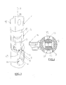
- the first connecting means (1) comprises an elongated body (15) with flattened sides (20), at the bottom changing into a narrower inserting part (11). At the top, the body (15) is connected to a lifting cord of a Jacquard machine, not represented in the drawings.
- the inserting part (11) has an upper cylindrical part (18) changing into a lower part (19) with smaller lateral dimensions than the upper part (18).
- an elongated opening (16) extending according to the longitudinal direction (A) has been provided.
- a respective flank part (12), (13) On both sides of the opening (16) a respective flank part (12), (13) has been formed on the lower part (19).
- These flank parts (12),(13) are projecting in opposite radial directions with respect to the upper walls of the lower part (19).
- flank parts (12),(13) have a respective top surface (6),(7) being situated practically across the longitudinal direction (A) of the first connecting means (1). As will be explained hereafter, these top surfaces (6),(7) are retained by a retaining edge (8) of the second connecting means (2) when these connecting means have been coupled.
- flank parts (12),(13) are narrowing in the direction of the extremity of the inserting part (11) and are changing into a common point (17) which forms the extremity of the inserting part (11), situated beyond the opening (16).
- the flank parts (12),(13) and the point (17) together constitute a whole having the form of an arrow and are made of elastically deformable material.
- this entity is called the coupling element (3).
- the second connecting means (2) has an upper part with an internal space in which the inserting part (11) of the first connecting means (1) may be received and a lower part with a so-called carbine coupling (14) for attaching one or several harness cords (not represented in the figures).
- the internal space consists of a passage (5), which exits at the top of the connecting means (2) on the one side and in a receiving part (4) into which the coupling element (3) may snap-fit and may be retained in the axial direction on the other side.
- windows (21), (22) In the walls of the second connecting means (2), near the receiving part two windows (21), (22) have been provided, situated opposite one another. These windows (21), (22) have an upper limiting edge (8) acting as a retaining edge for retaining the bumper edges (6),(7) of the coupling element, when this coupling element is situated in the receiving part (4). This retaining edge (8) changes stepwise into an edge part situated lower, so that a cam is formed.
- the coupling element (3) may be brought into the receiving part (4).
- This passage (5) has such lateral dimensions that, when the coupling element (3) is so orientated with respect to the second connecting means (2), that the flanks (12),(13) are situated above the windows (21),(22) (when it is situated in the coupling position), the coupling element (3) is elastically deformed in such a manner in the passage, so that its radial dimensions are reduced. The moment the flanks (12),(13) are brought beyond the passage (5), they end up in a respective window (21),(22) and resume their original radial dimensions, so that the bumper edges (6),(7) are retained by the retaining edges (8) of the respective windows.
- the coupling element (3) of the first connecting means (1) snap-fits into the receiving part (4) of the second connecting means (2).
- the coupling element (3) is situated in the coupling position (3) in the receiving part (4), while the inserting part (11) extends in the passage (5). This situation is represented in the figures 3, 4 and 7.
- the second connecting means (2) has a springy lip (10) at the top, which is situated such that it is pushed down by the lower edge of the body (15) of the first connecting means (1) when the connecting means (1),(2) are coupled.
- the spring force exerted by this lip (10) pushes the connecting means away from one another in the disconnecting direction, because of which the bumper edges (6),(7) are pushed against the retaining edges (8) and because of which undesired axial movements of the connecting means with respect to one another are prevented.
- the cam (9) prevents the two connecting means (1),(2) from being rotated around the longitudinal axis (A) with respect to one another.
- connection means (1),(2) In order to disengage the connecting means (1),(2), they must be pushed further towards one another in the coupling direction against the spring force of the springy lip (10), until the top of the coupling element (3) is brought beyond the cam (9). Than the first connecting means (1) may be rotated around its longitudinal axis (A) in the receiving part (4) into the position represented in the figures 5 and 6. In this position, called the disengaging position, the coupling element (3) may be drawn freely and without any deformation along the passage (5) from the second connecting means (2).
- These connecting means (1),(2) enable to realize a particularly reliable connection of a lifting cord and a harness cord of a Jacquard machine by one swift inserting movement according to the longitudinal axis of the connecting means (1),(2). Moreover, these connecting means are of a rather simple construction and user-friendly.
Landscapes
- Engineering & Computer Science (AREA)
- Textile Engineering (AREA)
- Quick-Acting Or Multi-Walled Pipe Joints (AREA)
- Details Of Connecting Devices For Male And Female Coupling (AREA)
- Electric Cable Arrangement Between Relatively Moving Parts (AREA)
- Mutual Connection Of Rods And Tubes (AREA)
- Buckles (AREA)
Applications Claiming Priority (2)
| Application Number | Priority Date | Filing Date | Title |
|---|---|---|---|
| BE200200299 | 2002-05-06 | ||
| BE2002/0299A BE1014814A5 (nl) | 2002-05-06 | 2002-05-06 | Verbindingsmidelen voor het losneembaar verbinden van koorden van een jacquardmachine. |
Publications (3)
| Publication Number | Publication Date |
|---|---|
| EP1361302A2 true EP1361302A2 (fr) | 2003-11-12 |
| EP1361302A3 EP1361302A3 (fr) | 2004-02-04 |
| EP1361302B1 EP1361302B1 (fr) | 2006-11-15 |
Family
ID=29220245
Family Applications (1)
| Application Number | Title | Priority Date | Filing Date |
|---|---|---|---|
| EP03076321A Expired - Lifetime EP1361302B1 (fr) | 2002-05-06 | 2003-04-30 | Dispositif de liaison pour connecter de manière amovible des arcades d'une mécanique Jacquard |
Country Status (4)
| Country | Link |
|---|---|
| US (1) | US6880582B2 (fr) |
| EP (1) | EP1361302B1 (fr) |
| BE (1) | BE1014814A5 (fr) |
| DE (1) | DE60309621T2 (fr) |
Cited By (3)
| Publication number | Priority date | Publication date | Assignee | Title |
|---|---|---|---|---|
| CN104136671A (zh) * | 2012-03-01 | 2014-11-05 | 米歇尔.范德威尔公司 | 用于将经纱定位在织机上的可拆卸地连接元件的设备 |
| CN107268140A (zh) * | 2016-04-07 | 2017-10-20 | 米歇尔.范德威尔公司 | 将织机上的经纱定位系统的元件可拆卸地连接的连接装置 |
| WO2017206275A1 (fr) * | 2016-05-31 | 2017-12-07 | 崔如奎 | Connecteur rapide d'un métier jacquard à grande vitesse |
Families Citing this family (4)
| Publication number | Priority date | Publication date | Assignee | Title |
|---|---|---|---|---|
| FR2888256B1 (fr) * | 2005-07-06 | 2007-09-21 | Staubli Lyon Sa | Dispositif d'accrochage entre elements d'un dispositif de formation de la foule, son procede de fabrication et procede d'accrochage au moyen d'un tel dispositif |
| BE1016685A3 (nl) * | 2005-07-15 | 2007-04-03 | Wiele Michel Van De Nv | Inrichting en werkwijze voor het borgen van de verbinding van een hevel en een harnaskoord. |
| CN100451200C (zh) * | 2006-08-18 | 2009-01-14 | 王占洪 | 编织机牵引杆连接扣 |
| BE1021506B1 (nl) * | 2012-11-19 | 2015-12-03 | Nv Michel Van De Wiele | Module geschikt voor inbouw in een jaquardmachine |
Family Cites Families (15)
| Publication number | Priority date | Publication date | Assignee | Title |
|---|---|---|---|---|
| US4513789A (en) * | 1983-06-13 | 1985-04-30 | The Baxter Corporation | Jacquard harness attachment mechanism |
| CH670114A5 (fr) * | 1986-04-11 | 1989-05-12 | Sulzer Ag | |
| JPS62276047A (ja) * | 1986-05-07 | 1987-11-30 | 横井産業株式会社 | 索体の連結装置 |
| EP0421370B1 (fr) * | 1989-10-03 | 1994-04-13 | Grosse Webereimaschinen GmbH | Palonnier pour machine Jacquard |
| FR2664913B1 (fr) * | 1990-07-17 | 1993-06-18 | Staubli Sa Ets | Dispositif pour l'accouplement des cadres de lisses et des elements de transmission d'une mecanique pour la formation de la foule. |
| DE4116163A1 (de) * | 1991-03-13 | 1992-09-17 | Textilma Ag | Fachbildevorrichtung fuer eine textilmaschine |
| FR2685015B1 (fr) * | 1991-12-12 | 1994-04-01 | Staubli Verdol Sa | Attache rapide pour la liaison d'au moins un element funiculaire par rapport a l'extremite d'un cordon. |
| DE4213958C1 (en) * | 1992-04-28 | 1993-04-15 | Schroers Jacquard-Papierindustrie Gmbh & Co., 4150 Krefeld, De | Installation for joining harness to jacquard machine - has 1st coupling element which gathers harness cords and is opt. connected to 2nd coupling element associated with jacquard machine |
| BE1008504A5 (nl) * | 1994-07-18 | 1996-05-07 | Wiele Michel Van De Nv | Beveiligende inrichting voor het snel verbinden van harnaskoorden met hefkoorden op een weefmachine. |
| FR2726010B3 (fr) * | 1994-10-24 | 1996-08-30 | Staubli Sa Ets | Collet demontable pour harnais de mecaniques jacquard |
| FR2726011B1 (fr) * | 1994-10-25 | 1996-12-20 | Staubli Sa Ets | Nouvel harnais demontable pour mecaniques jacquard |
| DE29801698U1 (de) * | 1997-11-19 | 1998-04-16 | Textilma Ag | Schnellverbinder zum Verbinden der Strupfe mit mindestens einer Harnischschnur |
| DE19839319C2 (de) * | 1998-08-28 | 2001-05-17 | Inst Textil & Faserforschung | Kupplungsvorrichtung |
| US6318415B1 (en) * | 1999-12-10 | 2001-11-20 | Wis Seaming Equipment Inc. | Quick release coupling/pulley assembly for improved weaving device |
| CZ10648U1 (en) * | 2000-10-11 | 2000-12-01 | Tre | Connecting device for cords |
-
2002
- 2002-05-06 BE BE2002/0299A patent/BE1014814A5/nl not_active IP Right Cessation
-
2003
- 2003-04-30 EP EP03076321A patent/EP1361302B1/fr not_active Expired - Lifetime
- 2003-04-30 DE DE60309621T patent/DE60309621T2/de not_active Expired - Lifetime
- 2003-05-06 US US10/429,966 patent/US6880582B2/en not_active Expired - Lifetime
Cited By (4)
| Publication number | Priority date | Publication date | Assignee | Title |
|---|---|---|---|---|
| CN104136671A (zh) * | 2012-03-01 | 2014-11-05 | 米歇尔.范德威尔公司 | 用于将经纱定位在织机上的可拆卸地连接元件的设备 |
| CN104136671B (zh) * | 2012-03-01 | 2017-03-01 | 米歇尔.范德威尔公司 | 用于将经纱定位在织机上的可拆卸地连接元件的设备 |
| CN107268140A (zh) * | 2016-04-07 | 2017-10-20 | 米歇尔.范德威尔公司 | 将织机上的经纱定位系统的元件可拆卸地连接的连接装置 |
| WO2017206275A1 (fr) * | 2016-05-31 | 2017-12-07 | 崔如奎 | Connecteur rapide d'un métier jacquard à grande vitesse |
Also Published As
| Publication number | Publication date |
|---|---|
| BE1014814A5 (nl) | 2004-04-06 |
| DE60309621D1 (de) | 2006-12-28 |
| EP1361302A3 (fr) | 2004-02-04 |
| EP1361302B1 (fr) | 2006-11-15 |
| DE60309621T2 (de) | 2007-03-08 |
| US6880582B2 (en) | 2005-04-19 |
| US20030221737A1 (en) | 2003-12-04 |
Similar Documents
| Publication | Publication Date | Title |
|---|---|---|
| EP1361302B1 (fr) | Dispositif de liaison pour connecter de manière amovible des arcades d'une mécanique Jacquard | |
| JPH08209480A (ja) | ジャカードシステムのハーネス | |
| US5671782A (en) | Harness to lifting cord three part connector for a jacquard weaving machine | |
| KR100345569B1 (ko) | 자카드 기계 하니스용으로 탈착가능한 넥 코드 | |
| US9399830B2 (en) | Device for detachably connecting elements for positioning warp yarns on a weaving loom | |
| EP3228739B1 (fr) | Moyens de connexion pour connecter amovible des éléments d'un système de positionnement de fils de chaîne sur un métier à tisser | |
| AU2003210194B2 (en) | Self-wringing mop | |
| US9915013B2 (en) | Shed forming device for a weaving machine | |
| ES2216382T3 (es) | Dispositivo de acoplamiento. | |
| CA2180923C (fr) | Poignee pour couvre-matelas | |
| US5483995A (en) | Device for coupling and uncoupling loom heald shafts | |
| CN106352077B (zh) | 限位销联动式选档互锁机构及变速箱 | |
| CN210596433U (zh) | 可释放连接器和包括这种可释放连接器的梭口装置 | |
| US7503352B2 (en) | Device and method for locking the connection of a heddle to a harness cord | |
| US4116242A (en) | Jacquard machine having means for controlling jacquard needle motion | |
| CN223054499U (zh) | 一种止血夹 | |
| CN207109202U (zh) | 快速接头、开口装置及提花机 | |
| CN224199593U (zh) | 一种牵拉耙 | |
| CN210383809U (zh) | 地拖把手固定装置及地拖把手 | |
| CN224081856U (zh) | 用于光纤连接器的推拉装置及光纤连接器 | |
| JP3065207B2 (ja) | ブラインド操作装置 | |
| KR100257968B1 (ko) | 소켓렌치와 같은 공구의 빠른 해제장치 | |
| KR200254538Y1 (ko) | 셔터용 연결구 | |
| KR19980070131A (ko) | 도비기 | |
| JPH08312269A (ja) | ブラインド |
Legal Events
| Date | Code | Title | Description |
|---|---|---|---|
| PUAI | Public reference made under article 153(3) epc to a published international application that has entered the european phase |
Free format text: ORIGINAL CODE: 0009012 |
|
| AK | Designated contracting states |
Kind code of ref document: A2 Designated state(s): AT BE BG CH CY CZ DE DK EE ES FI FR GB GR HU IE IT LI LU MC NL PT RO SE SI SK TR |
|
| AX | Request for extension of the european patent |
Extension state: AL LT LV MK |
|
| PUAL | Search report despatched |
Free format text: ORIGINAL CODE: 0009013 |
|
| AK | Designated contracting states |
Kind code of ref document: A3 Designated state(s): AT BE BG CH CY CZ DE DK EE ES FI FR GB GR HU IE IT LI LU MC NL PT RO SE SI SK TR |
|
| AX | Request for extension of the european patent |
Extension state: AL LT LV MK |
|
| 17P | Request for examination filed |
Effective date: 20040303 |
|
| 17Q | First examination report despatched |
Effective date: 20040521 |
|
| AKX | Designation fees paid |
Designated state(s): DE IT TR |
|
| GRAP | Despatch of communication of intention to grant a patent |
Free format text: ORIGINAL CODE: EPIDOSNIGR1 |
|
| GRAS | Grant fee paid |
Free format text: ORIGINAL CODE: EPIDOSNIGR3 |
|
| GRAA | (expected) grant |
Free format text: ORIGINAL CODE: 0009210 |
|
| AK | Designated contracting states |
Kind code of ref document: B1 Designated state(s): DE IT TR |
|
| REF | Corresponds to: |
Ref document number: 60309621 Country of ref document: DE Date of ref document: 20061228 Kind code of ref document: P |
|
| PLBE | No opposition filed within time limit |
Free format text: ORIGINAL CODE: 0009261 |
|
| STAA | Information on the status of an ep patent application or granted ep patent |
Free format text: STATUS: NO OPPOSITION FILED WITHIN TIME LIMIT |
|
| 26N | No opposition filed |
Effective date: 20070817 |
|
| PGFP | Annual fee paid to national office [announced via postgrant information from national office to epo] |
Ref country code: DE Payment date: 20210420 Year of fee payment: 19 Ref country code: IT Payment date: 20210427 Year of fee payment: 19 |
|
| PGFP | Annual fee paid to national office [announced via postgrant information from national office to epo] |
Ref country code: TR Payment date: 20210426 Year of fee payment: 19 |
|
| REG | Reference to a national code |
Ref country code: DE Ref legal event code: R119 Ref document number: 60309621 Country of ref document: DE |
|
| PG25 | Lapsed in a contracting state [announced via postgrant information from national office to epo] |
Ref country code: DE Free format text: LAPSE BECAUSE OF NON-PAYMENT OF DUE FEES Effective date: 20221103 |
|
| PG25 | Lapsed in a contracting state [announced via postgrant information from national office to epo] |
Ref country code: IT Free format text: LAPSE BECAUSE OF NON-PAYMENT OF DUE FEES Effective date: 20220430 |
|
| PG25 | Lapsed in a contracting state [announced via postgrant information from national office to epo] |
Ref country code: TR Free format text: LAPSE BECAUSE OF NON-PAYMENT OF DUE FEES Effective date: 20220430 |