EP1361412B1 - Quick-fit assembly for measuring and centering jigs used for vehicle wheel trim - Google Patents
Quick-fit assembly for measuring and centering jigs used for vehicle wheel trim Download PDFInfo
- Publication number
- EP1361412B1 EP1361412B1 EP03010474A EP03010474A EP1361412B1 EP 1361412 B1 EP1361412 B1 EP 1361412B1 EP 03010474 A EP03010474 A EP 03010474A EP 03010474 A EP03010474 A EP 03010474A EP 1361412 B1 EP1361412 B1 EP 1361412B1
- Authority
- EP
- European Patent Office
- Prior art keywords
- quick
- unit according
- wheel
- fit unit
- flange
- Prior art date
- Legal status (The legal status is an assumption and is not a legal conclusion. Google has not performed a legal analysis and makes no representation as to the accuracy of the status listed.)
- Expired - Lifetime
Links
- 230000002093 peripheral effect Effects 0.000 claims description 11
- 230000006835 compression Effects 0.000 claims description 5
- 238000007906 compression Methods 0.000 claims description 5
- 230000000694 effects Effects 0.000 claims description 2
- 238000005259 measurement Methods 0.000 description 6
- 238000009434 installation Methods 0.000 description 4
- 230000008878 coupling Effects 0.000 description 1
- 238000010168 coupling process Methods 0.000 description 1
- 238000005859 coupling reaction Methods 0.000 description 1
- 238000003780 insertion Methods 0.000 description 1
- 230000037431 insertion Effects 0.000 description 1
- 229910001234 light alloy Inorganic materials 0.000 description 1
- 238000000034 method Methods 0.000 description 1
- 230000000750 progressive effect Effects 0.000 description 1
Images


Classifications
-
- G—PHYSICS
- G01—MEASURING; TESTING
- G01B—MEASURING LENGTH, THICKNESS OR SIMILAR LINEAR DIMENSIONS; MEASURING ANGLES; MEASURING AREAS; MEASURING IRREGULARITIES OF SURFACES OR CONTOURS
- G01B5/00—Measuring arrangements characterised by the use of mechanical techniques
- G01B5/24—Measuring arrangements characterised by the use of mechanical techniques for measuring angles or tapers; for testing the alignment of axes
- G01B5/255—Measuring arrangements characterised by the use of mechanical techniques for measuring angles or tapers; for testing the alignment of axes for testing wheel alignment
Definitions
- This invention relates to quick-fit units for measuring and centering jigs for vehicle wheel trim.
- These known devices essentially comprise, for each wheel, a substantially circular flange provided with openings of predetermined shape to engage the attachment members with which the said devices are provided.
- a vehicle wheel alignment apparatus and method of use are known from US 4,854,702 according to which the apparatus has active light beam projecting instruments mounted on the front wheels to project beams longitudinally and transversely between the wheels of a vehicle, passive wheel position instruments on the wheels for reflecting incident beams to the active instruments, a system of mirrors associated with the active and passive instruments and beam targets for utilizing the system of mirrors and targets to find alignment information, and alignment data indicators responsive to the manipulation of the active instruments and responses from the passive instruments for visually revealing the alignment data and aiding and adjusting the wheels to specified alignment values.
- a second embodiment of these known devices provides that the flanges are provided with jaws which engage directly on the tyres, while support for the wheel is entrusted to a number of pins which extend perpendicularly from the flanges, directed towards the interior of the wheels, so that they rest against the brake discs and are held in contact with the same through the action of the jaws on the tyres.
- An axle measurement holder to fasten a measuring head to the rim of a vehicle wheel of this kind is know from US 5,987,761 .
- This axle measurement holder device includes a base body for direct or indirect stable contact with a rim of a vehicle wheel.
- Two arms arranged diametrically opposed feature respective hooks at their ends that are directed radially outwards to hook into a tread of a tyre.
- the ends of the arms directed radially outward the inside are attached by means of a pivot bearing to the end of a one armed lever, the end which is directed away from the base body, the outer end of which is connected to the base body via an articulation and tension springs.
- the one armed levers can be tensed radially inward by means of clamping devices.
- the one armed levers are each preloaded radially toward the outside by centring springs which exert the same forces and have the same characteristics and which are supported at a central point of the base body.
- the centring springs hold the arms and thereby the hooks located at their ends in any tensed position at the same radial distance to the axle that is defined by the axle shaft. This simplifies the attachment and clamping of the axle measurement holder device.
- a further installation device of gauge for wheel alignment is known from JP 04258701 .
- This installation device comprises two sockets into which a nut can be inserted, link which supports the socket in shiftable manner and a case which supports the link in swingable manner.
- An operating member which has an operation part which can contact with the link is shiftable in the axis line direction of a case, and an installation member having the installation part of a gage shifts the operating member.
- An adjusting member having a tilt adjusting plate is supported in shiftable manner in the axis line direction of the case. the socket is shifted towards the radius of a wheel by the force applied from the operating member through the link.
- Support on the wheels is a feature of fundamental importance for first detecting and then suitably and perfectly adjusting trim.
- a first disadvantage, associated essentially with devices provided with supports on the edges of the rims lies in the fact that in daily use the latter are subjected to impacts of variable strength against obstacles of all kinds such as pavements, holes, stones and so on.
- the main object of this invention is to overcome the abovementioned disadvantages of the known art by providing a quick-fit unit for measuring and centering jigs for vehicles' wheel trim which can be used on wheels of a special type, especially those fitted to fast cars and sports cars, which also makes it possible to have a secure and proper support without distortions so as to permit error-free measurement and adjustment.
- a particular object of this invention is to provide proper and secure attachment for measuring and centering jigs without the hazard of damaging rims in any way.
- this quick-fit unit for measuring and centering jigs for vehicles' wheel trim characterised in that it comprises at least one flange provided with means for attaching and supporting jigs, a central member integral with the said flange having an axis at right angles thereto and provided with expandable means for coupling and securing to the central hole of a wheel, means for operating the said expansion means, support and reference members for the said flange on a wheel.
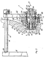
- 1 indicates as a whole a quick-fit unit for measuring and centering jigs for the trim of a vehicle wheel 2.
- unit 1 essentially comprises a flange 3 which is provided with jig attachment and supporting means, which are not illustrated and described in detail because they are of a known type and have no effect on this invention.
- a central member 4 having a longitudinal axis A at right angles to flange 3 is connected to flange 3.
- Member 4 is provided with expansion means 5 for connection and securing to central hole 6 of wheel 2, or more specifically rim 7 which is a component of it together with tyre 8.
- Expansion means 5 can be operated from the outside by means of a control member 9 and members 10 for support and reference with respect to wheel 2 are also secured to flange 3.
- Central member 4 comprises a first outer cylindrical body 11, referred to in brief below as first body 11, which is shaped substantially in the form of a sleeve and which can be secured to flange 3 by corresponding securing means, for example, as illustrated in Figure 1 , by corresponding stud bolts 12.
- First body 11 has an axial cavity 111 in which a second body 13, also substantially cylindrical and in the shape of a sleeve, is fitted so as to move coaxially.
- the second sleeve has an expanded end facing wheel 2 forming a peripheral surface 14 for support, bearing against the peripheral edge of central hole 6, and a seat 15 for housing expansion means 5.
- the opposite end of second body 13 has a hollow coaxial seat 16 for movably housing control member 9.
- first body 11 and second body 13 guide means 17 are provided to guide movement between the two which essentially comprise at least one through key 18 which can be screwed into a corresponding threaded hole 19 made transversely in first body 11 and a corresponding longitudinal groove 20 with blind ends made on the outer surface of second body 13 in which the tip 118 of key 18 is accurately engaged.
- first body 11 and second body 13 there are also elastic means 21 opposing mutual movement which comprise a hollow seat 22 with a blind end provided in a perimetral zone of first body 11 with an axis parallel to longitudinal axis A, and a helicoidal compression spring 23 housed in hollow seat 22.
- Seat 15 housing expansion means 5 comprises a cup member 26 which extends coaxially from the corresponding end of second body 13.
- Expansion means 5 in the first embodiment of the invention, comprises a conical or frustoconical expander member 27 which is mounted so as to move within cup 26 coaxially therewith and is secured to control member 9 as specified below, with the taper facing flange 3.
- Expansion member 27 acts on a plurality of small balls 28 which are included between the outer surface of the same and the inner walls of cup 26 and which can project from (or retract into) a plurality of substantially circular through holes 29 which are made in the periphery of the side wall of cup member 26.
- Through holes 29 have diameters which are slightly less than the diameters of small balls 28 so as to permit only the keyed portions to pass, to extend beyond the outer surface of cup 26. All through holes 29 lie in a first common plane 30 which is at right angles to longitudinal axis A and parallel to a second plane 30' in which perimetral supporting surface 14 bears against the peripheral edge of central hole 6. The distance between first plane 30 and second plane 30' can be adjusted using control member 9.
- Elastic compression means 31, comprising at least one helicoidal spring 32, are also placed between expander member 27 and the bottom of cup 26.
- the outer surface of expander member 27 has a number of radial grooves 33 to guide the movement of balls 28.
- Control member 9 of expander member 27 essentially comprises a rod 34 which is inserted to move coaxially within hollow seat 16, a threaded cavity 35 made coaxially with rod 34 at the end of the same facing wheel 2 and a threaded bolt 36 which engages threaded cavity 35.
- Bolt 36 has an outer head 136 through it can be engaged by control tools in two-directional rotation, in fact a dynamometric wrench 37, which can be seen in Figure 3 .
- Axial cavity 111 is provided with a closing cap 38 at the end of first body 11, the opposite end of which faces wheel 2.
- Cap 38 is passed through by a cavity 39 for the passage of head 136 in such a way as to form a supporting shoulder for the same.
- the opposite end of rod 34 facing wheel 2 can be firmly secured to thrust member 27 by securing means 39.
- Cap 38 can be immobilised against the end of axial cavity 111 through corresponding engaging means 40 which may comprise at least one threaded pin 41 which can be screwed into a matchingly threaded through hole 42 made transversely in first outer body 11 and of which inner end 141 can be engaged in a corresponding groove 142 made peripherally in cap 38.
- Means 39 securing rod 34 to thrust member 27 comprise a through cavity 43 made axially in member 27, a threaded shank 44 extending from the end of rod 34 and passing through through hole 43 and a nut 45 which can be screwed onto threaded shank 44.
- the supporting and adjustment members 10 for flange 3 comprise a plurality of rods 46 of identical length and of one piece with flange 3.
- Rods 46 which are normally four in number, extend at right angles from the surface of flange 3 facing wheel 2 to bear with their corresponding tips 146, which are coplanar with each other, in the configuration in which each central member 4 is coupled and secured to the corresponding central holes 6 of wheels 2 against discs 47 of the brake units with which a vehicle is provided.
- central member 4 also comprises a first outer cylindrical body 211 which is substantially in the shape of a sleeve and which can be secured to flange 3 by corresponding securing means, preferably a set of stud bolts 12.
- first body 211 in its axial cavity 148, there is mounted, in a way which can move coaxially, a second inner body 113 substantially in the shape of a cup and having an access opening 149 facing wheel 2 defining an annular edge 150 as a support bearing against the opposite peripheral edge 151 of central hole 6 of rim 7 of wheel 2.
- a seat 152 to house expansion means 5, the base of which is provided with a central hole 153 to permit the passage of control pin 9.
- first outer cylindrical body 211 and second inner cup-shaped body 113 are means 154 to guide the movement of the latter within said first member 211.
- Guide means 154 essentially comprise a through key 155 which can be screwed into a corresponding threaded hole 156 made transversely in first outer cylindrical body 211, a corresponding longitudinal groove 157 with blind ends made in the outer surface of second inner cup-shaped body 113 and in which the tip of key 155 can move with precise engagement.
- first cylindrical outer body 211 and second inner body 113 there are elastic means 158 which oppose the mutual movement.
- These elastic means comprise a hollow seat 159 made in first outer cylindrical body 211 with an axis parallel to longitudinal axis "AA" thereof and a supporting end comprising said flange 3, at least one helicoidal compression spring 160 housed in said hollow seat 159 and a perimetral shoulder 161 which extends from the outer surface of said inner cup-shaped body 113 which acts as a stop for helicoidal spring 160.
- expansion means 5 also comprise an expander member 162 which is mounted so as to move within second inner cup-shaped body 113 coaxially therewith and secured to control means 9.
- the taper of expander member 162 faces flange 3.
- Expansion means 5 also comprises at least one pair of facing half-shells 163 which can be moved apart by the progressive insertion of expander member 162 between them against the force of peripheral elastic containment means 164 and a perimetral edge 165 projecting outward from the ends of half-shells 163 facing central hole 6 of wheel 2.
- This perimetral edge 165 can be attached to an opposite inner edge 166 of central hole 6 when half-shells 163 are in a parted configuration.
- elastic opposing means 167 which are located between half-shells 163 and conical/frustoconical member 162 are provided in means 5.
- Control means 9 again comprises a bolt 168 which can be introduced coaxially to pass through flange 3 and central opening 153 passing between half-shells 163 and having a head 169 bearing, preferably through an intermediate block 170, against a surface opposite flange 3 with respect to wheel 2 and the opposite threaded end facing expander member 162 which can be engaged in a matching threaded seat 171 provided coaxially therein.
- Peripheral elastic opposing and containment means 164 comprise a number of elastic annular members 172 fitted peripherally on half-shells 163 in corresponding annular grooves made therein.
- the operator responsible for checking the trim offers up quick-fit unit 1 and abuts perimetral surface 14 of second body 13 against the perimetral edge of central hole 6 of wheel 2.
- support bolt 36 is first unscrewed from the exterior, for example using a dynamometric wrench 37 which can be engaged with head 136 of aforesaid bolt 36.
- rod 34 pushed by the relaxation of spring 32, moves in hollow seat 16 of second body 13 in the direction of central hole 6 of wheel 2.
- first body 11 moves onto second body 13 and progressively bring flange 3 closer to rim 7 of wheel 2 until the tips of rods 46 placed between the spokes of rim 7 are supported against disc 47 of the vehicle's braking unit.
- the operator can then fit the trim measuring and centering jig for wheel 2 on flange 3 using aforesaid disc 47, whose position is constantly stable on the vehicle, as a reference.
- half-shells 163 are normally held close together by elastic annular members 172 located peripherally in the corresponding annular grooves made therein.
- conical/frustoconical expander member 162 which engages between half-shells 163 is moved back towards flange 3 progressively separating them, overcoming the force of elastic annular members 172.
- first body 211 moves over second body 159 against spring 160, loading it under compression, and its relaxation will assist the operation of disengaging and removing unit 1.
- the measuring and centering tools for the vehicle's trim can be fitted to flange 3 and have the outer surface of the said brake discs, whose locations are substantially constant and certain, as a reference, eliminating any possible error due to imperfections in the support of flange 3 from the measurement readings.
Landscapes
- Physics & Mathematics (AREA)
- General Physics & Mathematics (AREA)
- Testing Of Balance (AREA)
- Automobile Manufacture Line, Endless Track Vehicle, Trailer (AREA)
- A Measuring Device Byusing Mechanical Method (AREA)
- Jigs For Machine Tools (AREA)
Applications Claiming Priority (2)
| Application Number | Priority Date | Filing Date | Title |
|---|---|---|---|
| ITMO20020114 | 2002-05-09 | ||
| IT2002MO000114A ITMO20020114A1 (it) | 2002-05-09 | 2002-05-09 | Gruppo di attacco rapido per strumenti di rilevamento e registrazionedell'assetto di ruote di veicoli |
Publications (3)
| Publication Number | Publication Date |
|---|---|
| EP1361412A2 EP1361412A2 (en) | 2003-11-12 |
| EP1361412A3 EP1361412A3 (en) | 2006-08-02 |
| EP1361412B1 true EP1361412B1 (en) | 2008-08-06 |
Family
ID=11451027
Family Applications (1)
| Application Number | Title | Priority Date | Filing Date |
|---|---|---|---|
| EP03010474A Expired - Lifetime EP1361412B1 (en) | 2002-05-09 | 2003-05-09 | Quick-fit assembly for measuring and centering jigs used for vehicle wheel trim |
Country Status (3)
| Country | Link |
|---|---|
| EP (1) | EP1361412B1 (it) |
| DE (1) | DE60322620D1 (it) |
| IT (1) | ITMO20020114A1 (it) |
Family Cites Families (4)
| Publication number | Priority date | Publication date | Assignee | Title |
|---|---|---|---|---|
| US3423839A (en) * | 1964-10-19 | 1969-01-28 | Fmc Corp | Apparatus for checking wheel alignment characteristics |
| US4854702A (en) * | 1987-12-14 | 1989-08-08 | Hunter Engineering Company | Vehicle wheel alignment apparatus and method of use |
| JPH04258701A (ja) * | 1991-02-12 | 1992-09-14 | Toyota Motor Corp | ホイールアライメント用ゲージの取付け装置 |
| DE19704163B4 (de) * | 1997-02-05 | 2005-03-10 | Warkotsch Horst | Achsmeßhalter zur Befestigung eines Meßkopfes an einer Felge eines Fahrzeugrades |
-
2002
- 2002-05-09 IT IT2002MO000114A patent/ITMO20020114A1/it unknown
-
2003
- 2003-05-09 EP EP03010474A patent/EP1361412B1/en not_active Expired - Lifetime
- 2003-05-09 DE DE60322620T patent/DE60322620D1/de not_active Expired - Lifetime
Also Published As
| Publication number | Publication date |
|---|---|
| ITMO20020114A0 (it) | 2002-05-09 |
| EP1361412A2 (en) | 2003-11-12 |
| DE60322620D1 (de) | 2008-09-18 |
| ITMO20020114A1 (it) | 2003-11-10 |
| EP1361412A3 (en) | 2006-08-02 |
Similar Documents
| Publication | Publication Date | Title |
|---|---|---|
| CN102770290B (zh) | 轮胎拆装机及测量力的变化的方法 | |
| US9254722B2 (en) | Tool for supporting and locking a rim or tired wheel for motorcycles | |
| JP7351965B2 (ja) | 車両ホイールの緊急操作用アタッチメント | |
| JP3002169B2 (ja) | 測定ヘッドを車両車輪のリムに固定するための軸測定ホルダ | |
| US6684516B2 (en) | Method and apparatus for wheel alignment adjustment | |
| US4097979A (en) | Guide tool for mounting vehicle wheels | |
| US4332169A (en) | Speed nut for a wheel balancer | |
| US4275594A (en) | Workpiece clamping device | |
| US4782706A (en) | Holding device for mounting an electric transducer | |
| MXPA05002327A (es) | Aparato y metodo de medicion de alineacion de vehiculo. | |
| US4176463A (en) | Wheel alignment gauge assembly and adapter therefor | |
| US10913316B2 (en) | Tire changer | |
| EP1361412B1 (en) | Quick-fit assembly for measuring and centering jigs used for vehicle wheel trim | |
| US4483177A (en) | Transducer calibration verification fixture for multiple spindle torque units | |
| US6507988B1 (en) | Automotive wheel camber alignment apparatus and method of aligning automotive wheels | |
| JP4162555B2 (ja) | ホイール付きタイヤのユニフォーミティ及び/または動釣合試験装置 | |
| WO2003031905A1 (en) | Automotive wheelless alignment device with sensor head | |
| US11879726B2 (en) | Method and apparatus for repairing truck and trailer axles | |
| US7451548B2 (en) | Device and method for measuring the geometry of a wheel axle of a motor vehicle | |
| WO2002074555A1 (en) | Aligning means for motor vehicle wheels | |
| US3402905A (en) | Attaching means for wheel gauges and the like | |
| JP4746755B2 (ja) | タイヤのユニフォーミティ及び/または動釣合試験装置 | |
| JP2003034104A (ja) | センサーまたはヘッドを支持する自動芯出し装置 | |
| US4381671A (en) | Tire mounting system | |
| US20070257546A1 (en) | Wheel centering tool and method |
Legal Events
| Date | Code | Title | Description |
|---|---|---|---|
| PUAI | Public reference made under article 153(3) epc to a published international application that has entered the european phase |
Free format text: ORIGINAL CODE: 0009012 |
|
| AK | Designated contracting states |
Kind code of ref document: A2 Designated state(s): AT BE BG CH CY CZ DE DK EE ES FI FR GB GR HU IE IT LI LU MC NL PT RO SE SI SK TR |
|
| AX | Request for extension of the european patent |
Extension state: AL LT LV MK |
|
| PUAL | Search report despatched |
Free format text: ORIGINAL CODE: 0009013 |
|
| AK | Designated contracting states |
Kind code of ref document: A3 Designated state(s): AT BE BG CH CY CZ DE DK EE ES FI FR GB GR HU IE IT LI LU MC NL PT RO SE SI SK TR |
|
| AX | Request for extension of the european patent |
Extension state: AL LT LV MK |
|
| 17P | Request for examination filed |
Effective date: 20060906 |
|
| 17Q | First examination report despatched |
Effective date: 20061016 |
|
| AKX | Designation fees paid |
Designated state(s): DE IT |
|
| GRAP | Despatch of communication of intention to grant a patent |
Free format text: ORIGINAL CODE: EPIDOSNIGR1 |
|
| GRAS | Grant fee paid |
Free format text: ORIGINAL CODE: EPIDOSNIGR3 |
|
| GRAA | (expected) grant |
Free format text: ORIGINAL CODE: 0009210 |
|
| AK | Designated contracting states |
Kind code of ref document: B1 Designated state(s): DE IT |
|
| REF | Corresponds to: |
Ref document number: 60322620 Country of ref document: DE Date of ref document: 20080918 Kind code of ref document: P |
|
| PLBE | No opposition filed within time limit |
Free format text: ORIGINAL CODE: 0009261 |
|
| STAA | Information on the status of an ep patent application or granted ep patent |
Free format text: STATUS: NO OPPOSITION FILED WITHIN TIME LIMIT |
|
| 26N | No opposition filed |
Effective date: 20090507 |
|
| PGFP | Annual fee paid to national office [announced via postgrant information from national office to epo] |
Ref country code: IT Payment date: 20110526 Year of fee payment: 9 |
|
| PGFP | Annual fee paid to national office [announced via postgrant information from national office to epo] |
Ref country code: DE Payment date: 20110705 Year of fee payment: 9 |
|
| PG25 | Lapsed in a contracting state [announced via postgrant information from national office to epo] |
Ref country code: IT Free format text: LAPSE BECAUSE OF NON-PAYMENT OF DUE FEES Effective date: 20120509 |
|
| REG | Reference to a national code |
Ref country code: DE Ref legal event code: R119 Ref document number: 60322620 Country of ref document: DE Effective date: 20121201 |
|
| PG25 | Lapsed in a contracting state [announced via postgrant information from national office to epo] |
Ref country code: DE Free format text: LAPSE BECAUSE OF NON-PAYMENT OF DUE FEES Effective date: 20121201 |