EP1362536A2 - Halter für einen Becher aus Eis - Google Patents
Halter für einen Becher aus Eis Download PDFInfo
- Publication number
- EP1362536A2 EP1362536A2 EP03018425A EP03018425A EP1362536A2 EP 1362536 A2 EP1362536 A2 EP 1362536A2 EP 03018425 A EP03018425 A EP 03018425A EP 03018425 A EP03018425 A EP 03018425A EP 1362536 A2 EP1362536 A2 EP 1362536A2
- Authority
- EP
- European Patent Office
- Prior art keywords
- support
- ice
- ice beaker
- beaker
- side wall
- Prior art date
- Legal status (The legal status is an assumption and is not a legal conclusion. Google has not performed a legal analysis and makes no representation as to the accuracy of the status listed.)
- Withdrawn
Links
- XLYOFNOQVPJJNP-UHFFFAOYSA-N water Substances O XLYOFNOQVPJJNP-UHFFFAOYSA-N 0.000 claims abstract description 45
- 238000002844 melting Methods 0.000 claims abstract description 19
- 230000008018 melting Effects 0.000 claims abstract description 19
- 230000000750 progressive effect Effects 0.000 claims abstract description 11
- 230000000452 restraining effect Effects 0.000 claims abstract description 8
- 230000015572 biosynthetic process Effects 0.000 claims abstract description 5
- 239000000463 material Substances 0.000 claims description 15
- 238000005192 partition Methods 0.000 claims description 15
- 238000004519 manufacturing process Methods 0.000 claims description 13
- 230000002093 peripheral effect Effects 0.000 claims description 7
- 125000006850 spacer group Chemical group 0.000 claims description 5
- 238000003860 storage Methods 0.000 claims description 4
- 229920002379 silicone rubber Polymers 0.000 claims description 3
- 239000004945 silicone rubber Substances 0.000 claims description 3
- 230000005494 condensation Effects 0.000 abstract description 13
- 238000009833 condensation Methods 0.000 abstract description 13
- 239000004033 plastic Substances 0.000 description 10
- 229920003023 plastic Polymers 0.000 description 10
- 238000000034 method Methods 0.000 description 8
- 230000035622 drinking Effects 0.000 description 6
- 238000001816 cooling Methods 0.000 description 5
- 238000007710 freezing Methods 0.000 description 4
- 230000008014 freezing Effects 0.000 description 4
- 238000009826 distribution Methods 0.000 description 3
- 239000000155 melt Substances 0.000 description 3
- 239000002184 metal Substances 0.000 description 3
- 229910052751 metal Inorganic materials 0.000 description 3
- 238000000465 moulding Methods 0.000 description 3
- 239000000047 product Substances 0.000 description 3
- 230000004888 barrier function Effects 0.000 description 2
- 238000007796 conventional method Methods 0.000 description 2
- 239000011521 glass Substances 0.000 description 2
- 238000010438 heat treatment Methods 0.000 description 2
- 238000004080 punching Methods 0.000 description 2
- 238000007789 sealing Methods 0.000 description 2
- 229910001220 stainless steel Inorganic materials 0.000 description 2
- 239000010935 stainless steel Substances 0.000 description 2
- RYGMFSIKBFXOCR-UHFFFAOYSA-N Copper Chemical compound [Cu] RYGMFSIKBFXOCR-UHFFFAOYSA-N 0.000 description 1
- 208000012661 Dyskinesia Diseases 0.000 description 1
- 208000015592 Involuntary movements Diseases 0.000 description 1
- 244000273618 Sphenoclea zeylanica Species 0.000 description 1
- 229910000831 Steel Inorganic materials 0.000 description 1
- 238000004140 cleaning Methods 0.000 description 1
- 238000004891 communication Methods 0.000 description 1
- 230000000295 complement effect Effects 0.000 description 1
- 238000010276 construction Methods 0.000 description 1
- 229910052802 copper Inorganic materials 0.000 description 1
- 239000010949 copper Substances 0.000 description 1
- 230000009977 dual effect Effects 0.000 description 1
- 229920001971 elastomer Polymers 0.000 description 1
- 238000007373 indentation Methods 0.000 description 1
- 238000003780 insertion Methods 0.000 description 1
- 238000011031 large-scale manufacturing process Methods 0.000 description 1
- 239000012263 liquid product Substances 0.000 description 1
- 230000017311 musculoskeletal movement, spinal reflex action Effects 0.000 description 1
- 238000000926 separation method Methods 0.000 description 1
- 230000035939 shock Effects 0.000 description 1
- 239000010959 steel Substances 0.000 description 1
- 230000009182 swimming Effects 0.000 description 1
- 238000003466 welding Methods 0.000 description 1
Images




Classifications
-
- A—HUMAN NECESSITIES
- A47—FURNITURE; DOMESTIC ARTICLES OR APPLIANCES; COFFEE MILLS; SPICE MILLS; SUCTION CLEANERS IN GENERAL
- A47G—HOUSEHOLD OR TABLE EQUIPMENT
- A47G23/00—Other table equipment
- A47G23/02—Glass or bottle holders
- A47G23/0208—Glass or bottle holders for drinking-glasses, plastic cups, or the like
- A47G23/0216—Glass or bottle holders for drinking-glasses, plastic cups, or the like for one glass or cup
-
- A—HUMAN NECESSITIES
- A47—FURNITURE; DOMESTIC ARTICLES OR APPLIANCES; COFFEE MILLS; SPICE MILLS; SUCTION CLEANERS IN GENERAL
- A47G—HOUSEHOLD OR TABLE EQUIPMENT
- A47G19/00—Table service
- A47G19/22—Drinking vessels or saucers used for table service
- A47G19/2288—Drinking vessels or saucers used for table service with means for keeping liquid cool or hot
-
- F—MECHANICAL ENGINEERING; LIGHTING; HEATING; WEAPONS; BLASTING
- F25—REFRIGERATION OR COOLING; COMBINED HEATING AND REFRIGERATION SYSTEMS; HEAT PUMP SYSTEMS; MANUFACTURE OR STORAGE OF ICE; LIQUEFACTION SOLIDIFICATION OF GASES
- F25C—PRODUCING, WORKING OR HANDLING ICE
- F25C1/00—Producing ice
- F25C1/04—Producing ice by using stationary moulds
- F25C1/045—Producing ice by using stationary moulds with the open end pointing downwards
-
- F—MECHANICAL ENGINEERING; LIGHTING; HEATING; WEAPONS; BLASTING
- F25—REFRIGERATION OR COOLING; COMBINED HEATING AND REFRIGERATION SYSTEMS; HEAT PUMP SYSTEMS; MANUFACTURE OR STORAGE OF ICE; LIQUEFACTION SOLIDIFICATION OF GASES
- F25C—PRODUCING, WORKING OR HANDLING ICE
- F25C1/00—Producing ice
- F25C1/22—Construction of moulds; Filling devices for moulds
-
- F—MECHANICAL ENGINEERING; LIGHTING; HEATING; WEAPONS; BLASTING
- F25—REFRIGERATION OR COOLING; COMBINED HEATING AND REFRIGERATION SYSTEMS; HEAT PUMP SYSTEMS; MANUFACTURE OR STORAGE OF ICE; LIQUEFACTION SOLIDIFICATION OF GASES
- F25D—REFRIGERATORS; COLD ROOMS; ICE-BOXES; COOLING OR FREEZING APPARATUS NOT OTHERWISE PROVIDED FOR
- F25D3/00—Devices using other cold materials; Devices using cold-storage bodies
- F25D3/02—Devices using other cold materials; Devices using cold-storage bodies using ice, e.g. ice-boxes
- F25D3/06—Movable containers
- F25D3/08—Movable containers portable, i.e. adapted to be carried personally
-
- F—MECHANICAL ENGINEERING; LIGHTING; HEATING; WEAPONS; BLASTING
- F25—REFRIGERATION OR COOLING; COMBINED HEATING AND REFRIGERATION SYSTEMS; HEAT PUMP SYSTEMS; MANUFACTURE OR STORAGE OF ICE; LIQUEFACTION SOLIDIFICATION OF GASES
- F25C—PRODUCING, WORKING OR HANDLING ICE
- F25C2600/00—Control issues
- F25C2600/04—Control means
-
- F—MECHANICAL ENGINEERING; LIGHTING; HEATING; WEAPONS; BLASTING
- F25—REFRIGERATION OR COOLING; COMBINED HEATING AND REFRIGERATION SYSTEMS; HEAT PUMP SYSTEMS; MANUFACTURE OR STORAGE OF ICE; LIQUEFACTION SOLIDIFICATION OF GASES
- F25D—REFRIGERATORS; COLD ROOMS; ICE-BOXES; COOLING OR FREEZING APPARATUS NOT OTHERWISE PROVIDED FOR
- F25D2303/00—Details of devices using other cold materials; Details of devices using cold-storage bodies
- F25D2303/08—Devices using cold storage material, i.e. ice or other freezable liquid
- F25D2303/081—Devices using cold storage material, i.e. ice or other freezable liquid using ice cubes or crushed ice
-
- F—MECHANICAL ENGINEERING; LIGHTING; HEATING; WEAPONS; BLASTING
- F25—REFRIGERATION OR COOLING; COMBINED HEATING AND REFRIGERATION SYSTEMS; HEAT PUMP SYSTEMS; MANUFACTURE OR STORAGE OF ICE; LIQUEFACTION SOLIDIFICATION OF GASES
- F25D—REFRIGERATORS; COLD ROOMS; ICE-BOXES; COOLING OR FREEZING APPARATUS NOT OTHERWISE PROVIDED FOR
- F25D2303/00—Details of devices using other cold materials; Details of devices using cold-storage bodies
- F25D2303/08—Devices using cold storage material, i.e. ice or other freezable liquid
- F25D2303/084—Position of the cold storage material in relationship to a product to be cooled
- F25D2303/0842—Position of the cold storage material in relationship to a product to be cooled inside the beverage contained in a bottle, can, drinking glass, pitcher or dispenser
-
- F—MECHANICAL ENGINEERING; LIGHTING; HEATING; WEAPONS; BLASTING
- F25—REFRIGERATION OR COOLING; COMBINED HEATING AND REFRIGERATION SYSTEMS; HEAT PUMP SYSTEMS; MANUFACTURE OR STORAGE OF ICE; LIQUEFACTION SOLIDIFICATION OF GASES
- F25D—REFRIGERATORS; COLD ROOMS; ICE-BOXES; COOLING OR FREEZING APPARATUS NOT OTHERWISE PROVIDED FOR
- F25D2303/00—Details of devices using other cold materials; Details of devices using cold-storage bodies
- F25D2303/08—Devices using cold storage material, i.e. ice or other freezable liquid
- F25D2303/084—Position of the cold storage material in relationship to a product to be cooled
- F25D2303/0843—Position of the cold storage material in relationship to a product to be cooled on the side of the product
-
- F—MECHANICAL ENGINEERING; LIGHTING; HEATING; WEAPONS; BLASTING
- F25—REFRIGERATION OR COOLING; COMBINED HEATING AND REFRIGERATION SYSTEMS; HEAT PUMP SYSTEMS; MANUFACTURE OR STORAGE OF ICE; LIQUEFACTION SOLIDIFICATION OF GASES
- F25D—REFRIGERATORS; COLD ROOMS; ICE-BOXES; COOLING OR FREEZING APPARATUS NOT OTHERWISE PROVIDED FOR
- F25D2303/00—Details of devices using other cold materials; Details of devices using cold-storage bodies
- F25D2303/08—Devices using cold storage material, i.e. ice or other freezable liquid
- F25D2303/084—Position of the cold storage material in relationship to a product to be cooled
- F25D2303/0845—Position of the cold storage material in relationship to a product to be cooled below the product
-
- F—MECHANICAL ENGINEERING; LIGHTING; HEATING; WEAPONS; BLASTING
- F25—REFRIGERATION OR COOLING; COMBINED HEATING AND REFRIGERATION SYSTEMS; HEAT PUMP SYSTEMS; MANUFACTURE OR STORAGE OF ICE; LIQUEFACTION SOLIDIFICATION OF GASES
- F25D—REFRIGERATORS; COLD ROOMS; ICE-BOXES; COOLING OR FREEZING APPARATUS NOT OTHERWISE PROVIDED FOR
- F25D2331/00—Details or arrangements of other cooling or freezing apparatus not provided for in other groups of this subclass
- F25D2331/80—Type of cooled receptacles
- F25D2331/808—Glasses
-
- F—MECHANICAL ENGINEERING; LIGHTING; HEATING; WEAPONS; BLASTING
- F25—REFRIGERATION OR COOLING; COMBINED HEATING AND REFRIGERATION SYSTEMS; HEAT PUMP SYSTEMS; MANUFACTURE OR STORAGE OF ICE; LIQUEFACTION SOLIDIFICATION OF GASES
- F25D—REFRIGERATORS; COLD ROOMS; ICE-BOXES; COOLING OR FREEZING APPARATUS NOT OTHERWISE PROVIDED FOR
- F25D2331/00—Details or arrangements of other cooling or freezing apparatus not provided for in other groups of this subclass
- F25D2331/80—Type of cooled receptacles
- F25D2331/809—Holders
Definitions
- the present invention relates to the field of ice beakers.
- the invention has been developed, in particular with regard to moulds for producing ice beakers and to a support for supporting such a beaker in use.
- German utility model DE 296 09 553 U relates to a support for use for ice beakers and to a system for producing them by means of complementary male and female moulds. It is known, from this document, to arrange the male and female moulds in a manner such that, when they are coupled, they form a series of cavities to be filled with water. When the water is frozen, it forms beaker-shaped frozen structures which are removed by separating the male mould from the female mould. In order to use an ice beaker of this type, it is necessary to provide a respective support which supports the beaker and possibly collects the water which is produced as the beaker gradually melts. Naturally, the support must be formed in a manner such that the water collected does not escape from the support when the support and the ice beaker are inclined for drinking.
- the above-mentioned utility model describes and illustrates a type of metal support with a frusto-conical body supported by a hollow stem in which the water produced as the ice beaker melts is collected.
- the side walls of the frusto-conical body widen out from the stem and are inclined in a manner substantially similar to the inclination of the walls of the ice beaker to be housed in the support.
- Extending from the upper edge of the frusto-conical support are elongate appendages at the ends of which stop pins are formed for welding to the outer wall of the ice beaker in order to hold it in position relative to the support, both in the erect position of the support and in the inclined position adopted by the support and by the ice beaker during drinking.
- Known supports have many disadvantages, the first of which is the fact that the ice beaker is not stable inside the support and, in particular, tends to move to and from to a greater extent the more its outer wall has melted. Moreover, as the ice beaker melts, it also tends to move down towards the base of the support so that its to and from movements can lead to some portions of the outer wall of the ice beaker moving towards the side wall of the support until they touch it; in this condition, some of the water of the melting ice beaker may find its route towards the base or stem of the support obstructed and may overflow from the support. This dripping outside the support is added to the condensation which forms on the outside of the support because of the intense cooling due to direct contact with the ice, possibly over quite large areas.
- a further disadvantage of known supports is that they are quite complex to manufacture and bulky to store. Moreover, the aesthetic form of these supports is defined at the production stage and it is therefore particularly expensive to differentiate production in order to offer for sale supports of various shapes and styles.
- An object of the present invention is to overcome the drawbacks of the prior art, first of all by proposing a support for an ice beaker which is easy to store or in any case compact, easy to use and of pleasant appearance.
- a further object of the invention is to propose a support for an ice beaker which supports an ice beaker firmly, even at an advanced stage of melting, and which drastically reduces the risk of water dripping out of the support.
- Another object of the invention is to provide a support of the type indicated above which is simple and inexpensive to produce so that its cost is quickly offset to the point at which it can even be used only once as a "disposable" product.
- the subject of the invention is a support for an ice beaker with an inclined outer wall which is characterized in that it comprises regions, arranged spaced apart along the height of the beaker when it is in the upright position, for supporting and restraining the outer wall of an ice beaker.
- the supporting and restraining regions comprise projections arranged spaced apart on the side wall of a beaker-shaped body and oriented towards the interior thereof, the side wall of the support being inclined to an extent substantially equal to the inclination of the side wall of the ice beaker.
- the projections are formed integrally with the beaker-shaped body which can advantageously be produced by moulding of a plastics material, although the possibility of using other materials should not be excluded.
- the arrangement of the projections may adopt a configuration such as additionally to confer an aesthetic quality on the support.
- An additional feature of the embodiment mentioned above is the presence of a flexible partition which can easily be removed from the support and which has the dual function of holding the water in the base of the support, even when the support is inclined for drinking, and of preventing the ice beaker from moving downwards in the support beyond a predetermined limit to prevent the ice from obstructing the regions in which the water flows towards the base of the support and/or to prevent the ice from coming into contact with relatively large areas of the side wall of the support.
- the support for an ice beaker comprises a spiral member the coils of which project inwardly relative to the side wall of the support.
- the spiral member conveys the water produced during the melting of the ice towards the base of the support and, at the same time, constitutes a barrier for the water which has collected in the base of the support when the support is inclined during drinking.
- the spiral member may be removable and, in this case, can be used in association with any conventional beaker the side wall of which is inclined to an extent substantially equal to the inclination of the side wall of the ice beaker.
- the spiral member may also be formed integrally on the side wall of a conventional beaker. In particular, it is possible to produce, in plastics material with programmed deformation, "disposable" beakers, the side walls of which can be deformed before use to form spiral recesses.
- One of the advantages of the present invention is, in particular, that the ability to manufacture "disposable" supports in large quantities from inexpensive plastics material can favour the use of ice beakers in large quantities, particularly in locations much frequented by the public.
- the number of ice beakers which can be produced by conventional methods by means of male and female moulds could be inadequate, particularly in view of the fairly long periods of time which are required for the water to freeze in the cavities defined between the male and female moulds.
- a further subject of the invention is an ice-making device particularly suitable for producing large quantities of ice beakers usable with a support of the type indicated above.
- a subject of the invention is a method of producing ice beakers, particularly for domestic use, in which the mould can act as a support for the ice beaker formed by freezing of the water in the mould.
- an ice beaker 10 comprises an inclined side wall 11, in particular, of frusto-conical shape, closed by a base 12, the whole being formed entirely of ice by means of known production methods, or of innovative methods described further below.
- the inclined side wall 11 comprises an outer surface 13 and an inner surface 14 which, together with the inner surface 12a of the base 12 defines a cavity 15 for holding a drink.
- the ice beaker can be housed in a goblet-like support 16 comprising a side wall 17 inclined to an extent substantially corresponding to the inclination of the side wall 11 of the ice beaker 10.
- the side wall 17 of the support 16 becomes narrower in its lower portion, where it is joined to a widened, hollow support foot 18 of the support 16.
- the internal cavity 18a of the foot 18 communicates, through an opening 21, with the internal space defined by the side wall 17.
- the goblet-like support 16 is preferably made of plastics material or of stainless steel, although the possibility of using materials of different types is not excluded.
- the arrangement of the dimples 19 may adopt the regular form shown in Figures 1 and 2 in which, purely by way of example and without excluding the possibility of the formation of different configurations, the upper and lower dimples are aligned along straight lines which are generatrices of the side wall 17 of the support 16.
- annular partition 20 preferably made of deformable or flexible material, for example, a silicone rubber suitable for use with foodstuffs.
- the annular partition 20 comprises a peripheral wall 22 from which a lower annular lip 23 extends and is inclined slightly downwards relative to a horizontal plane, defining a duct 24.
- Projecting appendages 25, which can best be seen in Figure 3, extend from the top of the peripheral wall 22 and define peripheral ducts 26.
- the shape and number of the projecting appendages 25 shown in the drawings is given purely by way of example.
- the ice beaker 10 is placed inside the goblet-like support 16 in a manner such that the outer surface 13 of the ice beaker bears against the dimples 19 in a plurality of support regions.
- the slight pressure exerted by the weight of the ice beaker 10 on the dimples 19, together with the difference in temperature between the regions in contact, causes local melting of the surface 13 so that the dimples 19 penetrate the side wall 11 of the ice beaker slightly, preventing it from moving to and from being displaced which could otherwise occur when the support 16, and the ice beaker therewith, are inclined by a user in order to drink or sip the product previously poured into the cavity 15.
- the dimples 19 also keep the ice beaker spaced from the side wall 17 of the support 16 so as to form a space in which the water which is produced during the slow melting of the ice beaker can flow.
- the water drips through the peripheral ducts 26, runs over the lower lip 23 of the annular partition 20, and is collected in the base of the goblet-like support 16, in the cavity 18a of the foot 18.
- the ice beaker can be used to drink the product contained therein as long as no cracks or holes are formed in the base 12 of the beaker because of the progressive melting of the ice. Until the melting reaches this advanced stage, the amount of water which collects in the base of the goblet-like support 16 is not excessive and is therefore stopped by the lower lip 23 of the partition 20 even when the goblet-like support 16 is inclined in order to drink from the ice beaker 10.
- the side wall 11 of the ice beaker 10 becomes thinner and the beaker tends to move downwards relative to the support 16.
- the downward movement of the ice beaker 10 relative to the goblet-like support 16 is in any case limited by the presence of the partition 20 and, in particular, by the projecting appendages 25 on which the base 12 bears until it is almost completely melted.
- the base 12 of the ice beaker 10 is bearing on the projecting appendages 25, the water can still drip towards the base 18 by virtue of the presence of the peripheral ducts 26.
- the support 16 can be re-used after removal of the water which has collected in its base.
- the deformability or flexibility of the partition 20, together with the inclination of the side wall 17 and the fact that the dimples 19 do not project excessively renders the removal of the partition 20 and its subsequent re-insertion in the support 16 quite easy.
- FIGS 4, 5 and 6 show another embodiment of a support according to the present invention.
- the ice beaker 10 is supported inside a beaker-shaped body 30 which may even be a conventional glass or plastics beaker, in which a rigid or flexible spiral element 31 has previously been inserted.
- the drawings show, by way of non-limiting example, a flexible spiral element 31, for example, made of silicone rubber suitable for use with foodstuffs, in which the coils 32 are spaced apart vertically by means of spacer feet 33, preferably formed integrally as appendages projecting from the coils 32.
- FIG. 6 shows in detail the cross-section of a preferred embodiment of the spiral element 31, in which each coil 32 comprises an outer edge 34 which bears sealingly on the side wall of the beaker-like body 30 and an inner edge 35 on which the outer surface 13 of the side wall 11 of the ice beaker 10 bears.
- the cross-section of the coils 32 may incorporate an inner core 36 of more rigid material, for example, a harmonic steel wire or a thread of resilient plastics material.
- the spacer feet 33 may in turn comprise respective bearing rims 37.
- the water which is produced during the progressive melting of the ice beaker 10 is collected by the spiral element 31 which directs it towards the base of the beaker-shaped body 30.
- the coils 32 of the spiral element 31 act as a barrier to the water, preventing it from escaping from the beaker-shaped body 30.
- the ice beaker 10 moves gradually downwards in the beaker-shaped body 30, encountering ever narrower coils 32 which in any case prevent the ice beaker from moving to and from.
- a support 40 with programmed deformation is provided in the form of a "disposable" beaker, for example, made of plastics material.
- the deformable support 40 has a substantially smooth frusto-conical side wall 41.
- An annular indentation 43 is preferably provided in the vicinity of the base 42 of the deformable support 41 to act as a spacer between one support and another in the storage and stowage configuration shown, so as to favour the removal and separation of one deformable support from another.
- Spiral deflection and deformation lines are predefined on the side wall 41 of the deformable support 40 so that, starting from the undeformed configuration of Figure 8, slight squashing of the deformable support 40 - possibly accompanied by slight twisting of the base 42 relative to the mouth - brings about the appearance of a spiral corrugation 44 in the side wall 41. It is thus possible to provide supports 40 in large quantities at a very low cost, enabling drinks to be supplied easily and inexpensively in ice beakers in locations much frequented by the public.
- the function of the deformable support 40 in use is substantially similar to that described above with reference to the spiral element 31 shown in Figures 4 to 6.
- Ice-making machines are generally known and will not therefore be discussed in detail.
- these machines comprise a condensation plate comprising recesses, normally made of metal, more particularly, nickel-plated copper, against which jets of water are directed by means of ejectors disposed under the plates.
- the plate is cooled to a temperature such as to bring about freezing of the water and the formation of small cubes or blocks of ice inside the recesses.
- known methods for producing ice by means of the above-mentioned machines comprise the steps of:
- an intermediate waiting step of predetermined duration preferably but in non-limiting manner, of about 30 seconds.
- the flow of atomized water directed towards the condensation plate is preferably maintained during the intermediate waiting step.
- the duration of which is, for example, about 30 minutes, the condensation plate is cooled to a temperature of about -10 C.
- One of the main advantages of this method consists of a reduction in the thermal shock to which the ice beakers are subjected, reducing the risks of breakage of the beakers.
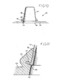
- Figures 10 and 11 show a specific embodiment of a condensation plate 50 comprising a base 51, preferably, but in non-limiting manner, made of plastics material, for example ABS, arranged horizontally and having circular openings 52 each having a shaped rim 53 in which there is a peripheral notch 54 in which a collar 55 of a cup-shaped vessel 56 with a substantially conical side wall 57 is engaged.
- the maximum inside diameter of the side wall 57 is slightly less than the diameter of the circular opening 52 so as to favour the detachment of a conical ice beaker upon completion of its formation inside the cup-shaped vessel 56 as a result of the freezing of water supplied by ejectors disposed beneath it.
- FIGS 12, 13 and 14 show an alternative system for the production and use of ice beakers in which moulds 60, for example, made of plastics material, preferably for "disposable" use, are provided, each mould comprising a male element 60a with a frusto-conical wall 61, a base 62, and an annular rim 63 which is turned outwards.
- the rim 63 is extended outwardly by an annular band 64 for connection to an opening 65 of a female element 60b also having a substantially frusto-conical wall 66 and a base 67.
- the annular connecting band 64 can be removed from the mould 60, for example, by means of a tab 64a so as to separate the male element 60a from the female element 60b, in use.
- the female element 60b has an annular rim 68,bent like a hook to form an annular seat 69.
- the base 67 has a central hole 70 from which an annular flange 71 extends.
- the side wall 66 has a slight spiral corrugation 72 or, as already described with reference to the embodiment of Figures 7 to 9, a spiral programmed-deformation region.
- moulds 60 can easily be stacked one upon another after the internal cavities defined by the male elements 60a and by the female elements 60b have been filled with water.
- the moulds thus filled and preferably stacked are placed in a freezer for the period of time necessary to freeze the water completely, forming ice beakers 10 housed in the moulds 60.
- Figures 15, 16 and 17 show an alternative embodiment of the mould for ice beakers which can also be used as an ice-beaker support.
- the mould comprises a main hourglass-shaped body 80 made, for example, of metal such as stainless steel, or glass, plastics material, rubber, etc.
- the hourglass-shaped body 80 comprises two portions with frusto-conical walls, comprising an upper portion 81 and a lower portion 82 joined by a common base of least width which defines a central communication duct 83.
- the inclination of the frusto-conical walls to a common axis Y-Y is preferably identical for the two portions 81 and 82 which, however, again preferably but in non-limiting manner, are of different heights and thus have respective mouths 81a and 82a of different diameters.
- Support members 84 for an ice beaker 10 are formed on the frusto-conical wall of the upper portion 81 the height of which is less than that of the lower portion 82.
- the support members may be formed by moulding or by punching in a manner similar to that described above with reference to Figures 1 and 2.
- the hourglass-shaped body 80 may advantageously be formed by deformation of a tube.
- the mould/support of Figures 15 to 17 further comprises a removable cap 85 with an annular wall 86 and a substantially conical re-entrant wall 87 the taper of which is similar to the inclination of the wall of the lower portion 82.
- the cap 85 is mounted in the mouth 82a of the lower portion 82 in a removable, leaktight manner by a connection of known type, for example, a screw, snap or pressure connection or a connection of another type, possibly with the interposition of a sealing member, for example, a sealing ring.
- the beaker thus produced can subsequently be housed in the upper portion 81 of the hourglass-shaped body 80 which has the spacer and support means 84, after the lower mouth 82a has been closed by the cap 85.
- the water produced during the progressive melting of the ice beaker 10 collects in the lower portion 82 of the hourglass-shaped body 80 and, by virtue of the undercut of the side wall of the lower portion 82 relative to the upper portion 81, does not escape even when the support is inclined in order to drink from the ice beaker.
Landscapes
- Engineering & Computer Science (AREA)
- Physics & Mathematics (AREA)
- Mechanical Engineering (AREA)
- Thermal Sciences (AREA)
- General Engineering & Computer Science (AREA)
- Chemical & Material Sciences (AREA)
- Combustion & Propulsion (AREA)
- Table Devices Or Equipment (AREA)
- Moulds For Moulding Plastics Or The Like (AREA)
- Jigs For Machine Tools (AREA)
- Confectionery (AREA)
- Details Of Rigid Or Semi-Rigid Containers (AREA)
- Sampling And Sample Adjustment (AREA)
- Supports For Plants (AREA)
- Beverage Vending Machines With Cups, And Gas Or Electricity Vending Machines (AREA)
- Table Equipment (AREA)
Applications Claiming Priority (3)
| Application Number | Priority Date | Filing Date | Title |
|---|---|---|---|
| IT1998BO000395A IT1304014B1 (it) | 1998-06-29 | 1998-06-29 | Stampi per la fabbricazione di bicchieri di ghiaccio e supporti persostenere tali bicchieri durante l'impiego. |
| ITBO980395 | 1998-06-29 | ||
| EP99929697A EP1100362B1 (de) | 1998-06-29 | 1999-06-28 | Verfahren zur Herstellung von Eistrinkbechern |
Related Parent Applications (2)
| Application Number | Title | Priority Date | Filing Date |
|---|---|---|---|
| EP99929697A Division EP1100362B1 (de) | 1998-06-29 | 1999-06-28 | Verfahren zur Herstellung von Eistrinkbechern |
| EP99929697.3 Division | 1999-06-28 |
Publications (2)
| Publication Number | Publication Date |
|---|---|
| EP1362536A2 true EP1362536A2 (de) | 2003-11-19 |
| EP1362536A3 EP1362536A3 (de) | 2010-03-03 |
Family
ID=11343267
Family Applications (2)
| Application Number | Title | Priority Date | Filing Date |
|---|---|---|---|
| EP99929697A Expired - Lifetime EP1100362B1 (de) | 1998-06-29 | 1999-06-28 | Verfahren zur Herstellung von Eistrinkbechern |
| EP03018425A Withdrawn EP1362536A3 (de) | 1998-06-29 | 1999-06-28 | Halter für einen Becher aus Eis |
Family Applications Before (1)
| Application Number | Title | Priority Date | Filing Date |
|---|---|---|---|
| EP99929697A Expired - Lifetime EP1100362B1 (de) | 1998-06-29 | 1999-06-28 | Verfahren zur Herstellung von Eistrinkbechern |
Country Status (10)
| Country | Link |
|---|---|
| US (1) | US6557351B1 (de) |
| EP (2) | EP1100362B1 (de) |
| JP (1) | JP4417564B2 (de) |
| AT (1) | ATE253209T1 (de) |
| AU (1) | AU4647099A (de) |
| CA (1) | CA2335057C (de) |
| DE (1) | DE69912435T2 (de) |
| ES (1) | ES2211111T3 (de) |
| IT (1) | IT1304014B1 (de) |
| WO (1) | WO2000000066A2 (de) |
Families Citing this family (21)
| Publication number | Priority date | Publication date | Assignee | Title |
|---|---|---|---|---|
| US6337552B1 (en) | 1999-01-20 | 2002-01-08 | Sony Corporation | Robot apparatus |
| KR100414980B1 (ko) * | 2002-04-23 | 2004-01-16 | 박창용 | 얼음가루를 이용한 얼음용기 제작장치 및 그의 제작방법 |
| ITBO20020657A1 (it) * | 2002-10-17 | 2004-04-18 | Reale S R L | Procedimento perfezionato per la realizzazione di bicchieri di ghiaccio |
| BR0303274A (pt) * | 2003-08-18 | 2004-02-10 | Alexandre Ji Su Lee | Copo com sistema para resfriamento e conservação de lìquidos |
| DE102004047421A1 (de) * | 2004-09-28 | 2006-04-20 | Rastal Gmbh & Co. Kg | Trinkgefäß |
| GB0515971D0 (en) * | 2005-08-03 | 2005-09-07 | Brand 21 Ltd | Drinking system |
| US7272950B1 (en) * | 2005-08-29 | 2007-09-25 | Jonathan Roman | Novelty enclosure for trapping dry ice in a drinking glass |
| NL2001114C2 (nl) * | 2007-12-21 | 2009-06-23 | Ditems Products B V | Malsamenstel. |
| US8800314B2 (en) * | 2010-10-22 | 2014-08-12 | General Electric Company | Misting ice maker for cup-shaped ice cubes and related refrigeration appliance |
| GB2510604B (en) * | 2013-02-08 | 2017-10-18 | Warnock Original Works | A Consumable Drinking Vessel Holder |
| JP5536273B1 (ja) | 2013-12-27 | 2014-07-02 | 赤城乳業株式会社 | 成型容器 |
| USD739038S1 (en) * | 2014-03-02 | 2015-09-15 | Helen Of Troy Limited | Beaker |
| JP6298913B1 (ja) * | 2017-04-14 | 2018-03-20 | 株式会社吉川国工業所 | 製氷用容器 |
| US11564519B1 (en) | 2019-02-08 | 2023-01-31 | Kayco, Inc. | Automatic self-adjusting beverage container receptacle |
| US11389020B2 (en) | 2019-03-21 | 2022-07-19 | JL Home Solutions, LLC | Container holder and methods relating to same |
| US11491479B2 (en) | 2020-01-22 | 2022-11-08 | Rolf Winter | Laboratory glassware and associated methods for using the same |
| USD930185S1 (en) | 2020-01-22 | 2021-09-07 | Rolf Winter | Laboratory glassware |
| US11620624B2 (en) | 2020-02-05 | 2023-04-04 | Walmart Apollo, Llc | Energy-efficient systems and methods for producing and vending ice |
| US12496535B2 (en) | 2022-11-03 | 2025-12-16 | Rolf Winter | Laboratory glassware |
| KR102822885B1 (ko) * | 2023-03-14 | 2025-06-19 | 주식회사 록서 | 컵 보조장치 |
| BE1031776B1 (nl) | 2023-07-06 | 2025-02-05 | Thibaud Entpr Bv | Werkwijze en inrichting voor het vervaardigen van ijsbekers |
Citations (1)
| Publication number | Priority date | Publication date | Assignee | Title |
|---|---|---|---|---|
| DE29609553U1 (de) | 1995-05-31 | 1996-08-22 | Hernfeld, Lukas, Wien | Trinkgefäß |
Family Cites Families (16)
| Publication number | Priority date | Publication date | Assignee | Title |
|---|---|---|---|---|
| US929389A (en) * | 1908-12-29 | 1909-07-27 | Thomas J Clement | Serving-cup for beverages. |
| US2048041A (en) * | 1935-10-21 | 1936-07-21 | James W Warren | Method and apparatus for serving iced drinks |
| US2961849A (en) * | 1956-06-04 | 1960-11-29 | Guy C Hitchcock | Mold for forming ice liners in containers |
| US2838916A (en) * | 1956-08-29 | 1958-06-17 | Leonel Planes Y Sola | Device for refrigerating beverage containers |
| US2921706A (en) * | 1958-02-05 | 1960-01-19 | Johnson Elvin | Protecting jacket for liquid containers |
| US2952133A (en) * | 1958-06-03 | 1960-09-13 | Frederick W Miller | Disposable frosted vessel |
| US2945361A (en) * | 1958-06-09 | 1960-07-19 | Frederick W Miller | Congelation apparatus |
| US3065606A (en) * | 1959-03-09 | 1962-11-27 | Lloyd W Reynolds | Drinking cup |
| US3279638A (en) * | 1965-04-12 | 1966-10-18 | James F Merry | Drip proof container |
| US4543801A (en) * | 1984-11-28 | 1985-10-01 | Damiens Bernard J A | Cool beverage carafe server |
| US4625518A (en) * | 1985-07-09 | 1986-12-02 | Freedman Saul E | Ice mug |
| ATE116735T1 (de) * | 1989-03-21 | 1995-01-15 | Josef Hobelsberger | Verfahren und vorrichtung zur herstellung von eisfiguren. |
| US5250315A (en) * | 1990-12-14 | 1993-10-05 | Design Display Group Inc. | Method for cooling a beverage |
| US5177981A (en) * | 1991-09-16 | 1993-01-12 | Raymond Haas | Drink cooler |
| DE9306465U1 (de) * | 1993-04-29 | 1993-07-08 | Grolman, Tassilo von, 6370 Oberursel | Einrichtung zum Herstellen und zum Halten eines Trinkbechereinsatzes |
| WO1995030865A1 (en) * | 1994-05-04 | 1995-11-16 | S & V Produktontwikkeling B.V. | Container made of ice |
-
1998
- 1998-06-29 IT IT1998BO000395A patent/IT1304014B1/it active
-
1999
- 1999-06-28 JP JP2000556656A patent/JP4417564B2/ja not_active Expired - Fee Related
- 1999-06-28 DE DE69912435T patent/DE69912435T2/de not_active Expired - Fee Related
- 1999-06-28 AU AU46470/99A patent/AU4647099A/en not_active Abandoned
- 1999-06-28 WO PCT/IT1999/000192 patent/WO2000000066A2/en not_active Ceased
- 1999-06-28 AT AT99929697T patent/ATE253209T1/de not_active IP Right Cessation
- 1999-06-28 CA CA002335057A patent/CA2335057C/en not_active Expired - Fee Related
- 1999-06-28 US US09/720,747 patent/US6557351B1/en not_active Expired - Fee Related
- 1999-06-28 ES ES99929697T patent/ES2211111T3/es not_active Expired - Lifetime
- 1999-06-28 EP EP99929697A patent/EP1100362B1/de not_active Expired - Lifetime
- 1999-06-28 EP EP03018425A patent/EP1362536A3/de not_active Withdrawn
Patent Citations (1)
| Publication number | Priority date | Publication date | Assignee | Title |
|---|---|---|---|---|
| DE29609553U1 (de) | 1995-05-31 | 1996-08-22 | Hernfeld, Lukas, Wien | Trinkgefäß |
Also Published As
| Publication number | Publication date |
|---|---|
| EP1100362A2 (de) | 2001-05-23 |
| AU4647099A (en) | 2000-01-17 |
| WO2000000066A3 (en) | 2000-04-27 |
| WO2000000066A2 (en) | 2000-01-06 |
| IT1304014B1 (it) | 2001-03-02 |
| EP1362536A3 (de) | 2010-03-03 |
| CA2335057A1 (en) | 2000-01-06 |
| EP1100362B1 (de) | 2003-10-29 |
| JP2002519083A (ja) | 2002-07-02 |
| US6557351B1 (en) | 2003-05-06 |
| CA2335057C (en) | 2008-02-05 |
| ATE253209T1 (de) | 2003-11-15 |
| JP4417564B2 (ja) | 2010-02-17 |
| DE69912435T2 (de) | 2004-08-12 |
| DE69912435D1 (de) | 2003-12-04 |
| ES2211111T3 (es) | 2004-07-01 |
| ITBO980395A1 (it) | 1999-12-29 |
Similar Documents
| Publication | Publication Date | Title |
|---|---|---|
| EP1100362B1 (de) | Verfahren zur Herstellung von Eistrinkbechern | |
| US4239175A (en) | Mold for forming frozen food product and cap member therefor | |
| US6032825A (en) | Lid for holding a frozen confection over a cup | |
| US4170320A (en) | Beverage container | |
| US20090071925A1 (en) | Two piece nestable bottle | |
| WO1995030865A1 (en) | Container made of ice | |
| CN2688653Y (zh) | 塑料饮用杯 | |
| US12326286B2 (en) | Apparatus for making clear molded ice, and corresponding methods | |
| JPH0689970B2 (ja) | 製氷機 | |
| CN220212561U (zh) | 冰饮杯 | |
| US7272935B1 (en) | Device and method for forming ice around a bottle | |
| CN219083461U (zh) | 一种冰球模具配件以及使用该配件的冰球模具 | |
| US20240053079A1 (en) | Ice mold for making ice straws | |
| JP3681056B2 (ja) | 飲料抽出装置 | |
| CN222335681U (zh) | 用于制作衬套型冰块的模具单元、模具组合及模具盒子 | |
| CN223295083U (zh) | 一体化制冰模具 | |
| EP1213550B1 (de) | Eiswürfelerzeuger | |
| AU756287B2 (en) | A drinking vessel used to assist swallowing tablets | |
| CN221076922U (zh) | 一种冰托架及应用冰托架的制冰机 | |
| JPH046672Y2 (de) | ||
| KR200258426Y1 (ko) | 음료 용기 | |
| US3423061A (en) | Mold with suction holders for confections | |
| KR100387563B1 (ko) | 배출부 일체형 용기의 제조방법 | |
| WO1998051591A1 (en) | An ice-cream holder | |
| JPH0519016Y2 (de) |
Legal Events
| Date | Code | Title | Description |
|---|---|---|---|
| PUAI | Public reference made under article 153(3) epc to a published international application that has entered the european phase |
Free format text: ORIGINAL CODE: 0009012 |
|
| AC | Divisional application: reference to earlier application |
Ref document number: 1100362 Country of ref document: EP Kind code of ref document: P |
|
| AK | Designated contracting states |
Kind code of ref document: A2 Designated state(s): AT BE CH CY DE DK ES FI FR GB GR IE IT LI LU MC NL PT SE |
|
| AX | Request for extension of the european patent |
Extension state: SI |
|
| RIC1 | Information provided on ipc code assigned before grant |
Ipc: F25C 1/04 20060101ALI20091030BHEP Ipc: F25C 1/22 20060101ALI20091030BHEP Ipc: F25D 3/08 20060101ALI20091030BHEP Ipc: A47G 23/02 20060101ALI20091030BHEP Ipc: A47G 19/22 20060101AFI20091030BHEP |
|
| PUAL | Search report despatched |
Free format text: ORIGINAL CODE: 0009013 |
|
| AK | Designated contracting states |
Kind code of ref document: A3 Designated state(s): AT BE CH CY DE DK ES FI FR GB GR IE IT LI LU MC NL PT SE |
|
| AX | Request for extension of the european patent |
Extension state: SI |
|
| RAP1 | Party data changed (applicant data changed or rights of an application transferred) |
Owner name: REALE S.R.L. |
|
| AKX | Designation fees paid |
Designated state(s): AT BE CH CY DE DK ES FI FR GB GR IE IT LI LU MC NL PT SE |
|
| AXX | Extension fees paid |
Extension state: SI Payment date: 20030827 |
|
| STAA | Information on the status of an ep patent application or granted ep patent |
Free format text: STATUS: THE APPLICATION IS DEEMED TO BE WITHDRAWN |
|
| 18D | Application deemed to be withdrawn |
Effective date: 20100904 |