EP1363049B1 - Dispositif de changement de vitesse avec cable - Google Patents
Dispositif de changement de vitesse avec cable Download PDFInfo
- Publication number
- EP1363049B1 EP1363049B1 EP20030010679 EP03010679A EP1363049B1 EP 1363049 B1 EP1363049 B1 EP 1363049B1 EP 20030010679 EP20030010679 EP 20030010679 EP 03010679 A EP03010679 A EP 03010679A EP 1363049 B1 EP1363049 B1 EP 1363049B1
- Authority
- EP
- European Patent Office
- Prior art keywords
- axis
- shift lever
- connecting element
- shift
- shift mechanism
- Prior art date
- Legal status (The legal status is an assumption and is not a legal conclusion. Google has not performed a legal analysis and makes no representation as to the accuracy of the status listed.)
- Expired - Lifetime
Links
- 230000008878 coupling Effects 0.000 claims description 27
- 238000010168 coupling process Methods 0.000 claims description 27
- 238000005859 coupling reaction Methods 0.000 claims description 27
- 230000005540 biological transmission Effects 0.000 description 6
- 238000006073 displacement reaction Methods 0.000 description 4
- 230000000694 effects Effects 0.000 description 1
- 230000000977 initiatory effect Effects 0.000 description 1
- 238000004519 manufacturing process Methods 0.000 description 1
Images
Classifications
-
- F—MECHANICAL ENGINEERING; LIGHTING; HEATING; WEAPONS; BLASTING
- F16—ENGINEERING ELEMENTS AND UNITS; GENERAL MEASURES FOR PRODUCING AND MAINTAINING EFFECTIVE FUNCTIONING OF MACHINES OR INSTALLATIONS; THERMAL INSULATION IN GENERAL
- F16H—GEARING
- F16H61/00—Control functions within control units of change-speed- or reversing-gearings for conveying rotary motion ; Control of exclusively fluid gearing, friction gearing, gearings with endless flexible members or other particular types of gearing
- F16H61/26—Generation or transmission of movements for final actuating mechanisms
- F16H61/36—Generation or transmission of movements for final actuating mechanisms with at least one movement being transmitted by a cable
Definitions
- the invention relates to a circuit device for a, over a cable to be switched, transmission of a motor vehicle according to the preamble of claim 1.
- a similar switching device is from the German patent application DE 41 28 161 A1 known.
- This document discloses a cable pulling device for a motor vehicle transmission, wherein the shift lever is mounted on a first and a second axis, which are arranged perpendicular to each other, and has coupling devices which transmit the movement of the shift lever to two cables.
- a first connecting element is mounted pivotably directly on the housing about the first axis, while the second connecting element is mounted in the first connecting element.
- the switching movement is initiated directly via the shift rod and the selection movement via a lever in the respective cable.
- a movement of the shift lever about the selector shaft is intended to substantially cause a longitudinal displacement of the one cable and a pivoting movement of the shift lever about the shift axis substantially a longitudinal displacement of the other cable substantially.
- the movements are not completely decoupled from each other, so that when a movement of the shift lever about the one axis, a lateral displacement of, responsible for the other axis cable is effected.
- these lateral displacements additionally burden the bearing of the cable, in particular at the point at which the core is introduced into the casing and lead to increased wear.
- document DE 195 44 837 A discloses a similar switching device showing the features of the preamble of claim 1.
- a cable pull circuit with a pivotally mounted shift lever, two connecting elements, which are each mounted pivotably about an axis, wherein the axes form a right angle to each other and the bearings of the connecting elements are arranged stationary in the housing or frame, and two coupling devices each connect a cable for transmitting selection and switching movements of the shift lever, wherein one of the connecting elements has a rotation axis for the shift lever, which is parallel to the axis of the other connecting element, and the other connecting element has a perpendicular to the axis of rotation sliding connection to the shift lever.
- this known switching device comprises a housing or a frame in which the switching device is mounted, and a pivotally mounted shift lever. Furthermore, the circuit device has a first connecting element, which is pivotally mounted about a first axis, and a second connecting element which is pivotable about a second axis, wherein the axes form a right angle to each other and the storage of at least one of the connecting elements in the housing or frame is arranged.
- a first, connected to the first connecting element, coupling device which connects a first cable for transmitting selection movements of the shift lever and a second, connected to the second connecting element, coupling device which connects a second cable for transmitting switching movements of the shift lever known.
- This known switching device is inventively improved to the effect that the bearings of both fasteners are arranged stationary in the housing or frame, one of the connecting elements has a bearing with a rotation axis for the shift lever, which is parallel to the axis of the other connecting element, and the other connecting element via a vertical to the axis of rotation sliding connection to the shift lever has.
- This inventive embodiment of the switching device in which the shift lever is mounted in total in three axes, wherein two of these axes are arranged parallel to each other, now allows the shift lever can perform Wählzien without movement components are transmitted to the responsible for the switching movements cable. Accordingly, switching movements can be performed by the shift lever, without the one hand, the responsible for the selector cable lateral loads undergoes and on the other hand a complete decoupling between the movements of the shift lever is achieved in the two axes.
- a movement of the shift lever about the one axis also exclusively for transmission to the one coupling device and a movement of the shift lever about the other axis also exclusively for transmission to the other coupling device, wherein mutual influences do not occur.
- the first axis and the second axis are arranged so that they lie on a common plane and accordingly intersect at a common point.
- both the first and the second axis lie on a common plane and the axis of rotation is arranged coaxially to the second axis, then the shift lever moves both in its selection movement and in its switching movement about a common center.
- the sliding connection between the first and the second connecting element may consist in that a recess in a connecting element and a sliding element engaging therein, which is connected to the shift lever, is provided.
- the reverse variant is also possible by the sliding element, which is connected to the shift lever, the connecting element comprises at least partially.
- the movement of the shift lever about the one axis can be transmitted to the connecting element, while movements perpendicular thereto do not move this connecting element.
- the connecting element at least in the region of the sliding connection, has a circular contour whose center lies on the axis of the other connecting element.
- the connecting element which carries the bearing of the shift lever, have a recess in which the shift lever can be pivoted about the axis of rotation.
- the necessary freedom of movement of the shift lever can be made available to the rotation axis, on the other hand, however, a limitation of this movement can be achieved by abutting the shift lever at the end of the recess.
- the storage of the connecting elements may, on the one hand, consist of the one connecting element or both connecting elements being cantilevered on one side.
- a connecting element or both connecting elements can each have two end bearing points, which are both connected to the housing.
- first or the second coupling element can be rigidly connected to the respective associated connecting element, wherein preferably the coupling element extends perpendicular to the axis of rotation of the respective coupling element.
- the coupling elements may comprise connecting pins as force introduction points for the respective cables, which lie in a central position of the shift lever in the plane which is formed by the first axis and the second axis.
- a cable pulling device so that the movements of the two cables, which are to transmit the selection movement or the switching movement, are completely decoupled from each other due to the triple bearing of the shift lever with two frame-mounted bearings, whereby the bearings of the cables - apart from the small deflection, due to the circular movement of the coupling elements - are loaded only in the longitudinal direction. Since the switching and Wählzien be introduced directly into the cables without using a further deflection, a particularly compact design of the switching device according to the invention is possible. The initiation of the switching and selection movement is, in contrast to conventional systems that allow an introduction of only about 90 ° or by deflection at a freely selectable angle to one of the axes, possible. Moreover, such a switching device according to the invention is characterized by a particularly low wear and low friction in the transmission of forces.
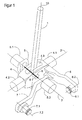
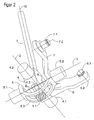
- FIGS. 1 and 2 show an embodiment of a cable pull circuit according to the invention, wherein the FIG. 1 a 3D view from diagonally above and the FIG. 2 a 3D view from diagonally below shows.
- the corresponding frame or the associated housing of the switching device was not shown in the schematic representation.
- the switching device has a shift lever 1, which is supported by a bearing 9 pivotally mounted in a connecting piece 4, wherein the connecting piece 4, the two end-mounted bearings on the frame, in which the two journals 4.1 and 4.2 engage connects.
- the shift lever 1 is pivotally mounted about the formed by the bearing 9, axis of rotation 8 within the connector 4, wherein the connector 4 has a recess 4.3 on the top and bottom through which the shift lever 1 passes through and so between the ends of Recess 4.3 can be pivoted over a predetermined sector.
- the connecting piece 4 can be pivoted about the switching axis 2, wherein the attached to the connecting piece 4 coupling arm 6 provides for a force transfer of the shift lever movement about the switching axis 2 on a, acting on the coupling arm 6, cable.
- the cable not shown here, is rotatably mounted about the bearing pin 6.1 about the journal axis 6.2.
- the journal axis 6.2 runs parallel to the indexing axis 2 here.
- the shift lever 1 which is thus mounted pivotably about an axis of rotation 8 and the switching axis 2, engages at its lower end with a sliding element 1.1 in an elongated recess 5.3 of the connecting piece 5 on the selector axis 3, wherein the connecting piece 5 of two journals 5.1 and 5.2 marginally limited. These trunnions, in turn, engage in stationary bearings in the frame or housing of the Switching device on.
- the connecting piece 5 extends outside the selection axis 3, so that a lever force can be transmitted to the connecting piece 5 by the sliding element 1.1 of the shift lever, as soon as the shift lever 1 is pivoted about its axis of rotation 8.
- the axis of rotation 8 is arranged coaxially to the selector axis 3.
- the switching axis 2, the selector axis 3 and the coaxial thereto extending axis of rotation 8 are on a common plane and intersect at a common point.
- a coupling arm 7 is further attached, which transmits via a pin 7.1, the switching movements of the shift lever 1 about the Wählachse 3 and the axis of rotation 8 on a cable connected thereto.
- FIG. 2 clarified in their view from below particularly clearly that here the contour of the connecting piece 5 is selected so that it extends on a circular arc on the switching axis 2, so that the sliding element 1.1, which is located in an extension of the shift lever 1, upon pivoting of the shift lever 1 can move around the selector shaft 3 slidably through the recess 5.3.
- each connecting piece can serve a common coupling arm for two ropes or a coupling arm per rope.
Landscapes
- Engineering & Computer Science (AREA)
- General Engineering & Computer Science (AREA)
- Mechanical Engineering (AREA)
- Gear-Shifting Mechanisms (AREA)
- Arrangement Or Mounting Of Control Devices For Change-Speed Gearing (AREA)
Claims (12)
- Dispositif de changement de vitesse pour une transmission, à commander par un câble de traction, d'un véhicule automobile, avec au moins :- un boîtier ou un cadre dans lequel est monté le dispositif de changement de vitesse,- un levier de changement de vitesse (1) monté pivotant,- un premier élément de liaison (4) qui est monté pivotant autour d'un premier axe (2), et un second élément de liaison (5) qui est monté pivotant autour d'un deuxième axe (3), les axes (2, 3) formant entre eux un angle droit et le support d'au moins l'un des éléments de liaison (4, 5) étant disposé de manière fixe dans le boîtier ou le cadre,- un premier dispositif d'accouplement (6) relié au premier élément de liaison (4) et qui relie un premier câble de traction pour la transmission des mouvements de sélection du levier de changement de vitesse (1),
et- un deuxième dispositif d'accouplement (7) relié au deuxième élément de liaison (5) et qui relie un deuxième câble de traction pour la transmission de mouvements de commutation du levier de changement de vitesses (1), dans lequel- les supports des deux éléments de liaison (4, 5) sont disposés de manière fixe dans le boîtier ou sur le cadre,- l'un des éléments de liaison (5) présente une liaison à glissement (5.3, 1.1) avec le levier de changement de vitesse (1), laquelle s'étend parallèlement à l'axe de rotation (8),
caractérisé en ce que- l'autre élément de liaison (4) comporte un support (9) avec un axe de rotation (8) pour le levier de changement de vitesse (2), lequel s'étend parallèlement à l'axe (3) de l'autre élément de liaison (5). - Dispositif de changement de vitesse selon la revendication 1 précédente, caractérisé en ce que le premier axe (2) et le second axe (3) sont disposés sur un plan.
- Dispositif de changement de vitesse selon l'une quelconque des revendications 1 ou 2, caractérisé en ce que l'axe de rotation (8) et le second axe (3) sont disposés coaxialement.
- Dispositif de changement de vitesse selon l'une quelconque des revendications 1 à 3, caractérisé en ce que la liaison à glissement présente une découpe (5.3) dans un élément de liaison (5) et un élément de glissement (1.1) s'engageant dans celle-ci, lequel est relié au levier de changement de vitesse (1).
- Dispositif de changement de vitesse selon l'une quelconque des revendications 1 à 3, caractérisé en ce que la liaison à glissement comporte un élément de glissement (1.1) qui est relié au levier de changement de vitesse (1) et qui comprend en même temps au moins en partie un élément de liaison (5).
- Dispositif de changement de vitesse selon l'une quelconque des revendications 4 ou 5, caractérisé en ce que l'élément de liaison (5) présente, au moins dans la zone de la liaison à glissement, un contour de forme circulaire dont le centre du cercle se situe sur l'axe (2) de l'autre élément de liaison (4).
- Dispositif de changement de vitesse selon l'une quelconque des revendications 1 à 6, caractérisé en ce que l'élément de liaison (4), qui porte le support (9) du levier de changement de vitesse (1), présente une découpe (4.3) dans laquelle le levier de changement de vitesse (1) peut pivoter autour de l'axe de rotation (8).
- Dispositif de changement de vitesse selon l'une quelconque des revendications 1 à 7, caractérisé en ce que le premier élément de liaison (4) possède deux points d'appui (4.1, 4.2) entre lesquels se trouve le levier de changement de vitesse.
- Dispositif de changement de vitesse selon l'une quelconque des revendications 1 à 8, caractérisé en ce que le second élément de liaison (5) possède deux points d'appui (5.1, 5.2) entre lesquels se trouve le levier de changement de vitesse (1).
- Dispositif de changement de vitesse selon l'une quelconque des revendications 1 à 9, caractérisé en ce que le premier élément d'accouplement (6) est relié rigidement au premier élément de liaison (4) et s'étend de préférence perpendiculairement au premier axe (2).
- Dispositif de changement de vitesse selon l'une quelconque des revendications 1 à 10, caractérisé en ce que le second élément d'accouplement (7) est relié rigidement au second élément de liaison (5) et s'étend de préférence perpendiculairement au second axe (3).
- Dispositif de changement de vitesse selon l'une quelconque des revendications 2 à 11, caractérisé en ce que les éléments d'accouplement (6, 7) comportent des tenons de liaison (6.1, 7.1) servant de points d'introduction des forces pour les câbles de traction respectifs, et les axes (6.2, 7.2) des pivots des tenons de liaison (6.1, 7.1) se situent, dans une position centrale du levier de changement de vitesse (1), dans un plan qui est formé par le premier axe (2) et le second axe (3).
Applications Claiming Priority (2)
| Application Number | Priority Date | Filing Date | Title |
|---|---|---|---|
| DE2002121520 DE10221520B4 (de) | 2002-05-14 | 2002-05-14 | Seilzugschaltung |
| DE10221520 | 2002-05-14 |
Publications (3)
| Publication Number | Publication Date |
|---|---|
| EP1363049A2 EP1363049A2 (fr) | 2003-11-19 |
| EP1363049A3 EP1363049A3 (fr) | 2006-11-02 |
| EP1363049B1 true EP1363049B1 (fr) | 2008-04-09 |
Family
ID=29265297
Family Applications (1)
| Application Number | Title | Priority Date | Filing Date |
|---|---|---|---|
| EP20030010679 Expired - Lifetime EP1363049B1 (fr) | 2002-05-14 | 2003-05-13 | Dispositif de changement de vitesse avec cable |
Country Status (3)
| Country | Link |
|---|---|
| EP (1) | EP1363049B1 (fr) |
| DE (1) | DE10221520B4 (fr) |
| ES (1) | ES2301726T3 (fr) |
Families Citing this family (4)
| Publication number | Priority date | Publication date | Assignee | Title |
|---|---|---|---|---|
| DE102008017861A1 (de) * | 2008-04-09 | 2009-10-29 | Dr. Ing. H.C. F. Porsche Aktiengesellschaft | Bedienrichtung für ein Handschaltgetriebe |
| DE102008017862B4 (de) * | 2008-04-09 | 2022-01-27 | Dr. Ing. H.C. F. Porsche Aktiengesellschaft | Bedieneinrichtung für ein Handschaltgetriebe |
| CN103438208B (zh) * | 2013-09-16 | 2016-02-10 | 盛瑞传动股份有限公司 | 一种挡位传感装置 |
| CN107061713B (zh) * | 2017-06-19 | 2024-08-02 | 浙江中马传动股份有限公司 | 汽车变速器选换挡操纵机构 |
Family Cites Families (4)
| Publication number | Priority date | Publication date | Assignee | Title |
|---|---|---|---|---|
| DE4128161A1 (de) * | 1990-09-06 | 1992-03-12 | Volkswagen Ag | Schalteinrichtung zur manuellen betaetigung eines mehrgaengigen kfz-wechselgetriebes mit rueckwaertsgang |
| FR2689460B1 (fr) * | 1992-04-07 | 1996-10-11 | Peugeot | Dispositif de commande d'une boite de vitesses de vehicule automobile. |
| DE19544837A1 (de) * | 1994-12-14 | 1996-06-20 | Volkswagen Ag | Gangschalteinrichtung zur manuellen Betätigung eines mehrgängigen Schaltgetriebes |
| DE19817166B4 (de) * | 1998-04-17 | 2008-01-31 | Fico Triad S.A., Rubi | Schalthebelelement |
-
2002
- 2002-05-14 DE DE2002121520 patent/DE10221520B4/de not_active Expired - Fee Related
-
2003
- 2003-05-13 EP EP20030010679 patent/EP1363049B1/fr not_active Expired - Lifetime
- 2003-05-13 ES ES03010679T patent/ES2301726T3/es not_active Expired - Lifetime
Also Published As
| Publication number | Publication date |
|---|---|
| DE10221520A1 (de) | 2003-11-27 |
| EP1363049A3 (fr) | 2006-11-02 |
| ES2301726T3 (es) | 2008-07-01 |
| DE10221520B4 (de) | 2005-02-10 |
| EP1363049A2 (fr) | 2003-11-19 |
Similar Documents
| Publication | Publication Date | Title |
|---|---|---|
| DE19636506B4 (de) | Schaltvorrichtung für ein Gangwechselgetriebe eines Kraftfahrzeuges | |
| DE68908925T2 (de) | Fernbetätigungseinrichtung. | |
| EP1558862B1 (fr) | Dispositif de changement de vitesse pour transmettre des instructions de changement de vitesse a une boite de vitesses automatique | |
| DE4020608C2 (de) | Schaltmechanismus für ein Geschwindigkeitswechselgetriebe | |
| DE102005001818B4 (de) | Schaltvorrichtung für ein Automatikgetriebe eines Kraftfahrzeuges | |
| EP0825364B1 (fr) | Dispositif de sélection pour boíte de vitesses automatique de véhicule automobile | |
| DE202008000715U1 (de) | Handschalthebelbaugruppe | |
| EP1363049B1 (fr) | Dispositif de changement de vitesse avec cable | |
| DE19544837A1 (de) | Gangschalteinrichtung zur manuellen Betätigung eines mehrgängigen Schaltgetriebes | |
| DE19520209B4 (de) | Schaltmechanismus für ein manuell schaltbares Getriebe | |
| DE102005060933B3 (de) | Wählhebel, insbesondere für ein Kraftfahrzeug | |
| EP1531290B1 (fr) | Dispositif de sélection de vitesse | |
| DE69602687T2 (de) | Steuerhebelanordnung mit verbesserter Positionsarretierung | |
| DE1238788B (de) | Progressive Lenkung fuer Kraftfahrzeuge | |
| WO2013068187A1 (fr) | Dispositif de changement de vitesse assurant le passage des vitesses dans une boîte de vitesses mécanique d'un véhicule | |
| DE102011087332B4 (de) | Schalthebelanordnung mit Wählübersetzung | |
| DE20310055U1 (de) | Handschalthebel für ein Fahrzeuggetriebe | |
| DE10255619A1 (de) | Manuelle Schaltvorrichtung | |
| EP0803664B1 (fr) | Dispositif de commande de vitesse manuelle pour commander une boíte de vitesses à plusieurs rapports | |
| DE19546813C2 (de) | Nehmer, insbesondere Getriebeanschluß für Kraftfahrzeuggetriebe | |
| EP3187753B1 (fr) | Dispositif de levier de sélection de vitesse destiné à sélectionner ou changer les rapports d'une boîte de vitesses manuelle d'un véhicule automobile | |
| DE102020109952A1 (de) | Lenk-Bedieneinheit mit kompakt verstaubarem Stellantrieb | |
| DE19542555C2 (de) | Außenschaltvorrichtung für ein Wechselgetriebe eines Kraftfahrzeuges | |
| EP0902214B1 (fr) | Dispositif de commande manuelle pour une boíte de vitesses | |
| EP0763172B1 (fr) | Dispositif de commande pour boítes de vitesses de véhicules |
Legal Events
| Date | Code | Title | Description |
|---|---|---|---|
| PUAI | Public reference made under article 153(3) epc to a published international application that has entered the european phase |
Free format text: ORIGINAL CODE: 0009012 |
|
| AK | Designated contracting states |
Kind code of ref document: A2 Designated state(s): AT BE BG CH CY CZ DE DK EE ES FI FR GB GR HU IE IT LI LU MC NL PT RO SE SI SK TR |
|
| AX | Request for extension of the european patent |
Extension state: AL LT LV MK |
|
| PUAL | Search report despatched |
Free format text: ORIGINAL CODE: 0009013 |
|
| AK | Designated contracting states |
Kind code of ref document: A3 Designated state(s): AT BE BG CH CY CZ DE DK EE ES FI FR GB GR HU IE IT LI LU MC NL PT RO SE SI SK TR |
|
| AX | Request for extension of the european patent |
Extension state: AL LT LV MK |
|
| 17P | Request for examination filed |
Effective date: 20070116 |
|
| AKX | Designation fees paid |
Designated state(s): ES FR GB IT SE |
|
| REG | Reference to a national code |
Ref country code: DE Ref legal event code: 8566 |
|
| GRAP | Despatch of communication of intention to grant a patent |
Free format text: ORIGINAL CODE: EPIDOSNIGR1 |
|
| GRAS | Grant fee paid |
Free format text: ORIGINAL CODE: EPIDOSNIGR3 |
|
| GRAA | (expected) grant |
Free format text: ORIGINAL CODE: 0009210 |
|
| AK | Designated contracting states |
Kind code of ref document: B1 Designated state(s): ES FR GB IT SE |
|
| REG | Reference to a national code |
Ref country code: GB Ref legal event code: FG4D Free format text: NOT ENGLISH |
|
| REG | Reference to a national code |
Ref country code: SE Ref legal event code: TRGR |
|
| REG | Reference to a national code |
Ref country code: ES Ref legal event code: FG2A Ref document number: 2301726 Country of ref document: ES Kind code of ref document: T3 |
|
| ET | Fr: translation filed | ||
| PLBE | No opposition filed within time limit |
Free format text: ORIGINAL CODE: 0009261 |
|
| STAA | Information on the status of an ep patent application or granted ep patent |
Free format text: STATUS: NO OPPOSITION FILED WITHIN TIME LIMIT |
|
| 26N | No opposition filed |
Effective date: 20090112 |
|
| PGFP | Annual fee paid to national office [announced via postgrant information from national office to epo] |
Ref country code: GB Payment date: 20100329 Year of fee payment: 8 |
|
| PGFP | Annual fee paid to national office [announced via postgrant information from national office to epo] |
Ref country code: ES Payment date: 20100611 Year of fee payment: 8 |
|
| PGFP | Annual fee paid to national office [announced via postgrant information from national office to epo] |
Ref country code: SE Payment date: 20100510 Year of fee payment: 8 |
|
| REG | Reference to a national code |
Ref country code: SE Ref legal event code: EUG |
|
| GBPC | Gb: european patent ceased through non-payment of renewal fee |
Effective date: 20110513 |
|
| PG25 | Lapsed in a contracting state [announced via postgrant information from national office to epo] |
Ref country code: GB Free format text: LAPSE BECAUSE OF NON-PAYMENT OF DUE FEES Effective date: 20110513 |
|
| PGFP | Annual fee paid to national office [announced via postgrant information from national office to epo] |
Ref country code: FR Payment date: 20120608 Year of fee payment: 10 |
|
| PGFP | Annual fee paid to national office [announced via postgrant information from national office to epo] |
Ref country code: IT Payment date: 20120516 Year of fee payment: 10 |
|
| PG25 | Lapsed in a contracting state [announced via postgrant information from national office to epo] |
Ref country code: SE Free format text: LAPSE BECAUSE OF NON-PAYMENT OF DUE FEES Effective date: 20110514 |
|
| REG | Reference to a national code |
Ref country code: ES Ref legal event code: FD2A Effective date: 20130606 |
|
| PG25 | Lapsed in a contracting state [announced via postgrant information from national office to epo] |
Ref country code: ES Free format text: LAPSE BECAUSE OF NON-PAYMENT OF DUE FEES Effective date: 20110514 |
|
| PG25 | Lapsed in a contracting state [announced via postgrant information from national office to epo] |
Ref country code: IT Free format text: LAPSE BECAUSE OF NON-PAYMENT OF DUE FEES Effective date: 20130513 |
|
| REG | Reference to a national code |
Ref country code: FR Ref legal event code: ST Effective date: 20140131 |
|
| PG25 | Lapsed in a contracting state [announced via postgrant information from national office to epo] |
Ref country code: FR Free format text: LAPSE BECAUSE OF NON-PAYMENT OF DUE FEES Effective date: 20130531 |