EP1364752A2 - Outil à main électrique avec transmission à plusieurs étages - Google Patents
Outil à main électrique avec transmission à plusieurs étages Download PDFInfo
- Publication number
- EP1364752A2 EP1364752A2 EP03101261A EP03101261A EP1364752A2 EP 1364752 A2 EP1364752 A2 EP 1364752A2 EP 03101261 A EP03101261 A EP 03101261A EP 03101261 A EP03101261 A EP 03101261A EP 1364752 A2 EP1364752 A2 EP 1364752A2
- Authority
- EP
- European Patent Office
- Prior art keywords
- switching
- transmission
- bracket
- power tool
- tool according
- Prior art date
- Legal status (The legal status is an assumption and is not a legal conclusion. Google has not performed a legal analysis and makes no representation as to the accuracy of the status listed.)
- Granted
Links
Images


Classifications
-
- B—PERFORMING OPERATIONS; TRANSPORTING
- B25—HAND TOOLS; PORTABLE POWER-DRIVEN TOOLS; MANIPULATORS
- B25F—COMBINATION OR MULTI-PURPOSE TOOLS NOT OTHERWISE PROVIDED FOR; DETAILS OR COMPONENTS OF PORTABLE POWER-DRIVEN TOOLS NOT PARTICULARLY RELATED TO THE OPERATIONS PERFORMED AND NOT OTHERWISE PROVIDED FOR
- B25F5/00—Details or components of portable power-driven tools not particularly related to the operations performed and not otherwise provided for
- B25F5/001—Gearings, speed selectors, clutches or the like specially adapted for rotary tools
Definitions
- the invention relates to a power tool with a mounted in a gear housing, multi-stage transmission and with a switching device for switching the transmission of a gear stage in another gear, the one spring-loaded, in several Switching stages can be brought slide switch and one, actuated by this, on an axial having displaceable ratchet wheel acting, resiliently formed switch bracket.
- Power tools of the above type have, stored in a gear housing, Multi-stage transmission and a switching device for switching the transmission of a gear stage in another gear stage to the speed of one for the application reaching tool, such as a screwdriver bit or drill to the conditions adapt.
- a power tool with a, mounted in a gear housing, multi-stage transmission and with a switching device for switching the transmission from one gear stage to another gear stage.
- the transmission has a spring-loaded, can be brought into several stages shift slide and a, from this actuated resiliently acting on an axially displaceable ratchet wheel Switch bracket on.
- a disadvantage of the known solution is that in a transmission with more than two gears several slide valves are necessary.
- the present invention is based on the object, an economically producible and to create a handy multi-speed transmission.
- the object is achieved in that the transmission has a plurality of axially displaceable Has switching wheels, each ratchet interacts with a shift bracket and the switch bracket can be actuated by means of the slide switch.
- the gearbox has more than two courses. Furthermore, all switching elements can be actuated by the operation of the slide switch and thereby ensures a high degree of handiness.
- By an axial displacement of the Shift valve is a switching of the transmission from one gear stage to another Gear stage safely ensured.
- the spring-trained switch bracket ensure a Safe switching, especially when switching the gearbox at standstill, as the Shift bracket engage the corresponding parts of the transmission, at the latest at one Drive of the gearbox.
- the switch brackets preferably each have one, fixedly arranged on the transmission housing, Swivel axis on to a defined switching position of the switching wheels and thus a reliable To ensure switching.
- the transmission housing for leadership arranged the shift bracket bearing parts, in particular through holes, the area wise Recording the switch bracket.
- each switch bracket each has at least one engagement part and at least a switching part for switching the corresponding switching wheel, wherein the engaging part interacts with the corresponding ratchet and the switching part as a transmission means the actuating force from the slide switch to the engaging part is used.
- the slide switch preferably has at least one recess for supporting the switching part on, and thus ensures a compact design of the transmission. Moreover a recess is economical to produce and facilitates the final assembly of the transmission.
- the recess is preferably transverse to the longitudinal axis of the transmission and substantially tangentially formed to the switching wheels through to a simple final assembly and ensure safe guidance of the switching part in the slide switch.
- the recess advantageously has a control link for pivoting in the longitudinal direction the switch bracket to the pivot pocket on to a structurally simple and to ensure economic control of the switch bracket by the slide switch.
- the Control link pivots depending on the position of the slide switch individual control arms and thereby shifts the corresponding to the respective switch bracket ratchet.
- the switch bracket pass through the recess advantageously with their respective switching part, which acts as a connecting part.
- the recess transverse to the longitudinal axis of the transmission preferably has a height which essentially corresponds to the diameter of the switching part with a game to an optimal To ensure switching.
- the game allows in the manufacture of the transmission a higher tolerance and thereby has a positive economic effect on the production costs out.
- the control link advantageously has two switching stages, wherein different and mutually corresponding switching stages are connected to each other by a ramp.
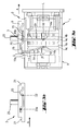
- a transmission 1 of an inventive power tool is shown to the working direction A a tool holder 11 for receiving a tool holder, For example, a ringerb itfact connects.
- the transmission 1 has a substantially cylindrical transmission housing 6, for example is made of plastic or the like, and a switching device for switching of the transmission 1 from one gear stage to another gear stage.
- the Transmission 1 a spring-loaded, in three, in particular in Fig. 1a to 3a shown, Switching stages can be brought on switch slide 3 and a first and second switch bracket 5a, 5b, each acting on a corresponding axially displaceable ratchet wheel 4a, 4b.
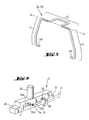
- a U-shaped switching bracket 5a, 5b is shown, which is a switching part 15 and two engagement members 14, wherein the two engagement members 14 each have free ends 14a of the switching bracket 5a, 5b form and the switching part 15, the two engaging parts 14 with each other combines.
- the free end 14a of the engaging parts 14 is about 90 ° relative to the rest Angled engaging member 14, so that the free ends 14a of the switch bracket 5a, 5b against each other are directed and in each case a corresponding recess in the form of a Ring groove 4c on which the switching bracket 5a, 5b associated switching wheel 4a, 4b can be brought.
- the two engagement parts 14 pass through the transmission housing 6 with their free ends 14a by respectively corresponding, diametrically arranged and axially extending Longitudinal holes 18.
- the switching bracket 5a, 5b are resilient, for example made of spring steel or similar.
- For pivotable mounting of the switching bracket 5a, 5b has the Transmission housing 6 two, provided with through holes, bearing elements 19a, 19b on which the switch bracket 5a, 5b pivotable about a pivot axis S on the transmission housing 6 store.
- the switching bracket 5a, 5b pass through the switching part 15, respectively, the two corresponding through holes next to the slide switch 3rd
- Fig. 6 substantially having a cuboid outer contour
- Slide switch 3 is mounted axially displaceable on the transmission housing 6 and has a, transverse to the longitudinal axis L of the transmission 1 and substantially tangential to the switching wheels 4a, 4b continuously formed recess, in particular a control link 20.
- the Control link 20 extends axially to the gear 1 and has at the two longitudinal ends respectively a taper 21 for storage on the transmission housing 6.
- the switching bracket 5a, 5b pass through the control link 20 each with the switching member 15 and are in the control link 20th mounted pivotably relative to the pivot axis S.
- control link 20 has two switching stages 22, 23, wherein different and mutually corresponding switching stages 22a, 23a by a Ramp 24a are interconnected.
- the slide switch 3 at the of Gear housing 6 side facing away from an actuator 25 for the placement of the Slide valve 3 on.
- the slide switch 3 By the slide switch 3, the transmission 1 between three different gears switchable.
- the slide switch 3 is shown with the control slide 20, wherein the switching parts 15 are shown in cross-section to their positions in the control link 20 clearly in the three different courses.
- the transmission 1 in first gear and the two shift yokes 5a, 5b are perpendicular to the longitudinal axis L. of the transmission 1, as can be seen in particular from Fig. 1b.
- Fig. 2b is the Shift slide 3 in contrast to those in Fig. 1a and 1b in the direction of A moved shown and the transmission 1 in second gear.
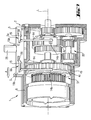
- transmission 1 has two, in the longitudinal direction L of the transmission 1, successively arranged planetary gear, as is known from the prior Technics are well known.
- the transmission 1 instead two successively connected planetary gear, a planetary gear 31 and a spur gear 32 on.
Landscapes
- Engineering & Computer Science (AREA)
- Mechanical Engineering (AREA)
- Gear-Shifting Mechanisms (AREA)
- Portable Power Tools In General (AREA)
Applications Claiming Priority (2)
| Application Number | Priority Date | Filing Date | Title |
|---|---|---|---|
| DE10222824A DE10222824A1 (de) | 2002-05-21 | 2002-05-21 | Elektrowerkzeug mit mehrstufigem Getriebe |
| DE10222824 | 2002-05-21 |
Publications (3)
| Publication Number | Publication Date |
|---|---|
| EP1364752A2 true EP1364752A2 (fr) | 2003-11-26 |
| EP1364752A3 EP1364752A3 (fr) | 2005-07-13 |
| EP1364752B1 EP1364752B1 (fr) | 2008-02-20 |
Family
ID=29285659
Family Applications (1)
| Application Number | Title | Priority Date | Filing Date |
|---|---|---|---|
| EP03101261A Expired - Lifetime EP1364752B1 (fr) | 2002-05-21 | 2003-05-07 | Outil à main électrique avec transmission à plusieurs étages |
Country Status (4)
| Country | Link |
|---|---|
| US (1) | US6860341B2 (fr) |
| EP (1) | EP1364752B1 (fr) |
| JP (1) | JP4486790B2 (fr) |
| DE (2) | DE10222824A1 (fr) |
Cited By (10)
| Publication number | Priority date | Publication date | Assignee | Title |
|---|---|---|---|---|
| EP1886768A1 (fr) * | 2006-08-09 | 2008-02-13 | TTS Tooltechnic Systems AG & Co. KG | Machine-outil dotée d'engrenages à plusieurs étapes |
| EP1886769A1 (fr) * | 2006-08-09 | 2008-02-13 | TTS Tooltechnic Systems AG & Co. KG | Machine-outil dotée d'un train épicycloïdal à plusieurs niveaux |
| US8292001B2 (en) | 2007-11-21 | 2012-10-23 | Black & Decker Inc. | Multi-mode drill with an electronic switching arrangement |
| CN103101032A (zh) * | 2011-11-14 | 2013-05-15 | 松下电器产业株式会社 | 切换操作装置 |
| CN103358290A (zh) * | 2012-03-26 | 2013-10-23 | 罗伯特·博世有限公司 | 用于工具机的可切换的传动装置的换挡装置 |
| EP2316620A3 (fr) * | 2009-10-29 | 2013-11-13 | C. & E. Fein GmbH | Outil manuel |
| CN104646724A (zh) * | 2013-11-22 | 2015-05-27 | 创科电动工具科技有限公司 | 多速摆线传动 |
| DE102015105333A1 (de) | 2015-04-08 | 2016-10-13 | Metabowerke Gmbh | Werkzeugmaschine |
| CN103358290B (zh) * | 2012-03-26 | 2016-11-30 | 罗伯特·博世有限公司 | 用于工具机的可切换的传动装置的换挡装置 |
| DE102015119987A1 (de) | 2015-11-18 | 2017-05-18 | C. & E. Fein Gmbh | Handwerkzeugmaschine mit schaltbarem Getriebe |
Families Citing this family (35)
| Publication number | Priority date | Publication date | Assignee | Title |
|---|---|---|---|---|
| DE102004058175B4 (de) * | 2004-12-02 | 2019-10-31 | Robert Bosch Gmbh | Handwerkzeugmaschine mit anatomisch verbessertem Schaltelement |
| US7980324B2 (en) * | 2006-02-03 | 2011-07-19 | Black & Decker Inc. | Housing and gearbox for drill or driver |
| DE102006035386A1 (de) * | 2006-10-31 | 2008-05-08 | Hilti Ag | Elektrowerkzeug mit mehrstufigem Getriebe |
| DE102006061600A1 (de) | 2006-12-27 | 2008-07-03 | Metabowerke Gmbh | Elektrohandwerkzeuggerät |
| US20090065225A1 (en) * | 2007-09-07 | 2009-03-12 | Black & Decker Inc. | Switchable anti-lock control |
| US7717191B2 (en) | 2007-11-21 | 2010-05-18 | Black & Decker Inc. | Multi-mode hammer drill with shift lock |
| US7735575B2 (en) | 2007-11-21 | 2010-06-15 | Black & Decker Inc. | Hammer drill with hard hammer support structure |
| US7717192B2 (en) | 2007-11-21 | 2010-05-18 | Black & Decker Inc. | Multi-mode drill with mode collar |
| US7762349B2 (en) | 2007-11-21 | 2010-07-27 | Black & Decker Inc. | Multi-speed drill and transmission with low gear only clutch |
| US7854274B2 (en) | 2007-11-21 | 2010-12-21 | Black & Decker Inc. | Multi-mode drill and transmission sub-assembly including a gear case cover supporting biasing |
| US7770660B2 (en) | 2007-11-21 | 2010-08-10 | Black & Decker Inc. | Mid-handle drill construction and assembly process |
| EP2110921B1 (fr) * | 2008-04-14 | 2013-06-19 | Stanley Black & Decker, Inc. | Système de gestion de batterie pour outil sans fil |
| DE102008042033A1 (de) | 2008-09-12 | 2010-03-18 | Robert Bosch Gmbh | Handwerkzeugmaschine mit einer schaltbaren Mechanik |
| US8251158B2 (en) | 2008-11-08 | 2012-08-28 | Black & Decker Inc. | Multi-speed power tool transmission with alternative ring gear configuration |
| DE102008044273B4 (de) * | 2008-12-02 | 2019-10-02 | Robert Bosch Gmbh | Handwerkzeugmaschine mit einem schaltbaren Getriebe |
| DE102009054931A1 (de) * | 2009-12-18 | 2011-06-22 | Robert Bosch GmbH, 70469 | Handgeführtes Elektrowerkzeug mit einer Drehmomentkupplung |
| DE102009054927B4 (de) * | 2009-12-18 | 2025-12-18 | Robert Bosch Gmbh | Handwerkzeugmaschine, insbesondere Akkuhandwerkzeugmaschine |
| DE102009060929A1 (de) * | 2009-12-23 | 2011-06-30 | C. & E. Fein GmbH, 73529 | Handwerkzeug |
| US9289886B2 (en) | 2010-11-04 | 2016-03-22 | Milwaukee Electric Tool Corporation | Impact tool with adjustable clutch |
| EP2551063B1 (fr) | 2011-07-27 | 2014-04-02 | C. & E. Fein GmbH | Dispositif de commutation et machine-outil avec un dispositif de commutation |
| DE102011081661B4 (de) * | 2011-08-26 | 2023-11-30 | Robert Bosch Gmbh | Schaltbares Getriebe für eine Handwerkzeugmaschine |
| US9108312B2 (en) | 2012-09-11 | 2015-08-18 | Milwaukee Electric Tool Corporation | Multi-stage transmission for a power tool |
| CN204686830U (zh) | 2012-10-19 | 2015-10-07 | 米沃奇电动工具公司 | 锤钻 |
| EP2842697A1 (fr) * | 2013-09-02 | 2015-03-04 | HILTI Aktiengesellschaft | Machine-outil manuelle |
| DE102014217863A1 (de) * | 2014-05-16 | 2015-11-19 | Robert Bosch Gmbh | Handwerkzeugmaschine |
| CN108400629B (zh) | 2014-05-18 | 2023-01-24 | 百得有限公司 | 电池组 |
| US9893384B2 (en) | 2014-05-18 | 2018-02-13 | Black & Decker Inc. | Transport system for convertible battery pack |
| US9862116B2 (en) | 2014-11-20 | 2018-01-09 | Black & Decker Inc. | Dual speed gearboxes, transmissions, and apparatuses incorporating the same |
| KR102502980B1 (ko) * | 2016-08-08 | 2023-02-22 | 하이토크 디비젼 유넥스 코포레이션 | 나사식 체결구를 조이기 위한 장치 |
| WO2018119256A1 (fr) | 2016-12-23 | 2018-06-28 | Black & Decker Inc. | Système d'outil électrique sans fil |
| DE102017119808A1 (de) | 2017-08-29 | 2019-02-28 | Festool Gmbh | Hand-Werkzeugmaschine |
| DE102018111792A1 (de) | 2017-08-29 | 2019-02-28 | Festool Gmbh | Hand-Werkzeugmaschine |
| US10932781B2 (en) * | 2018-02-06 | 2021-03-02 | Ethicon Llc | Features to align and close linear surgical stapler |
| CN115302232A (zh) * | 2022-08-29 | 2022-11-08 | 大连德新机电技术工程有限公司 | 拧紧机 |
| DE102022212712A1 (de) | 2022-11-28 | 2024-05-29 | Robert Bosch Gesellschaft mit beschränkter Haftung | Handwerkzeugmaschine mit einem schaltbaren Getriebe |
Family Cites Families (19)
| Publication number | Priority date | Publication date | Assignee | Title |
|---|---|---|---|---|
| US2911841A (en) * | 1958-07-02 | 1959-11-10 | Vance V Miller | Portable electric hand drill |
| US3500696A (en) * | 1968-07-25 | 1970-03-17 | Rockwell Mfg Co | Two-speed power tool |
| GB1404063A (en) * | 1972-05-24 | 1975-08-28 | Desoutter Brothers Ltd | Power driven rotary tool |
| US3934688A (en) * | 1974-09-11 | 1976-01-27 | The Black And Decker Manufacturing Company | Shifter mechanism |
| JPS5915765B2 (ja) * | 1981-10-05 | 1984-04-11 | 松下電工株式会社 | 回転式電動工具の変速装置 |
| DE3525208A1 (de) * | 1984-07-16 | 1986-01-23 | Japan Strage Battery Co. Ltd., Kyoto | Untersetzungsgetriebe |
| US4710071A (en) * | 1986-05-16 | 1987-12-01 | Black & Decker Inc. | Family of electric drills and two-speed gear box therefor |
| DE3904085A1 (de) * | 1989-02-11 | 1990-08-23 | Licentia Gmbh | Elektrowerkzeug mit einem mehrstufigen getriebe und mit einer im stillstand betaetigbaren einrichtung zum umschalten des getriebes |
| JPH03221384A (ja) * | 1990-01-26 | 1991-09-30 | Matsushita Electric Works Ltd | 回転工具 |
| US5339908A (en) * | 1990-10-02 | 1994-08-23 | Ryobi Limited | Power tool |
| JP2501142Y2 (ja) * | 1990-10-02 | 1996-06-12 | リョービ株式会社 | 電動工具 |
| JP2585716Y2 (ja) * | 1992-03-13 | 1998-11-25 | 日立工機株式会社 | 電動工具の変速装置 |
| US5550416A (en) * | 1995-02-09 | 1996-08-27 | Fanchang; We C. | Control mechanism of revolving speed of an electric tool |
| DE29904051U1 (de) * | 1999-03-05 | 1999-06-17 | Chung, Lee Hsin-Chih, Chungli, Taoyuan | Schalteinrichtung für ein Reduktionsgetriebe |
| JP2000288960A (ja) * | 1999-04-01 | 2000-10-17 | Mobiletron Electronics Co Ltd | 電動工具の速度を変える制御機構 |
| JP3696493B2 (ja) * | 2000-09-29 | 2005-09-21 | 株式会社マキタ | 遊星歯車式変速装置 |
| US6676557B2 (en) * | 2001-01-23 | 2004-01-13 | Black & Decker Inc. | First stage clutch |
| US6431289B1 (en) * | 2001-01-23 | 2002-08-13 | Black & Decker Inc. | Multi-speed power tool transmission |
| DE10156392B4 (de) * | 2001-11-16 | 2008-04-10 | Robert Bosch Gmbh | Gangschaltvorrichtung für ein mehrstufiges Getriebe eines Elektrowerkzeugs |
-
2002
- 2002-05-21 DE DE10222824A patent/DE10222824A1/de not_active Withdrawn
-
2003
- 2003-05-07 EP EP03101261A patent/EP1364752B1/fr not_active Expired - Lifetime
- 2003-05-07 DE DE50309184T patent/DE50309184D1/de not_active Expired - Lifetime
- 2003-05-20 US US10/442,041 patent/US6860341B2/en not_active Expired - Lifetime
- 2003-05-21 JP JP2003143623A patent/JP4486790B2/ja not_active Expired - Lifetime
Cited By (19)
| Publication number | Priority date | Publication date | Assignee | Title |
|---|---|---|---|---|
| EP1886769A1 (fr) * | 2006-08-09 | 2008-02-13 | TTS Tooltechnic Systems AG & Co. KG | Machine-outil dotée d'un train épicycloïdal à plusieurs niveaux |
| EP1886768A1 (fr) * | 2006-08-09 | 2008-02-13 | TTS Tooltechnic Systems AG & Co. KG | Machine-outil dotée d'engrenages à plusieurs étapes |
| US8292001B2 (en) | 2007-11-21 | 2012-10-23 | Black & Decker Inc. | Multi-mode drill with an electronic switching arrangement |
| EP2316620A3 (fr) * | 2009-10-29 | 2013-11-13 | C. & E. Fein GmbH | Outil manuel |
| US9108308B2 (en) | 2011-11-14 | 2015-08-18 | Panasonic Intellectual Property Management Co., Ltd. | Switch operation device |
| CN103101032A (zh) * | 2011-11-14 | 2013-05-15 | 松下电器产业株式会社 | 切换操作装置 |
| CN103101032B (zh) * | 2011-11-14 | 2015-04-01 | 松下电器产业株式会社 | 切换操作装置 |
| CN103358290B (zh) * | 2012-03-26 | 2016-11-30 | 罗伯特·博世有限公司 | 用于工具机的可切换的传动装置的换挡装置 |
| CN103358290A (zh) * | 2012-03-26 | 2013-10-23 | 罗伯特·博世有限公司 | 用于工具机的可切换的传动装置的换挡装置 |
| US9739366B2 (en) | 2012-03-26 | 2017-08-22 | Robert Bosch Gmbh | Gear shift device for a shiftable gear unit of a power tool |
| EP2875906A1 (fr) * | 2013-11-22 | 2015-05-27 | Techtronic Power Tools Technology Limited | Transmission cycloïdale multivitesse |
| CN104646724A (zh) * | 2013-11-22 | 2015-05-27 | 创科电动工具科技有限公司 | 多速摆线传动 |
| US9217492B2 (en) | 2013-11-22 | 2015-12-22 | Techtronic Power Tools Technology Limited | Multi-speed cycloidal transmission |
| US9636818B2 (en) | 2013-11-22 | 2017-05-02 | Techtronic Power Tools Technology Limited | Multi-speed cycloidal transmission |
| CN104646724B (zh) * | 2013-11-22 | 2019-02-05 | 创科电动工具科技有限公司 | 多速摆线传动 |
| DE102015105333A1 (de) | 2015-04-08 | 2016-10-13 | Metabowerke Gmbh | Werkzeugmaschine |
| DE102015105333B4 (de) | 2015-04-08 | 2021-11-25 | Metabowerke Gmbh | Werkzeugmaschine mit Schalteinrichtung |
| DE102015119987A1 (de) | 2015-11-18 | 2017-05-18 | C. & E. Fein Gmbh | Handwerkzeugmaschine mit schaltbarem Getriebe |
| DE102015119987B4 (de) | 2015-11-18 | 2024-01-25 | C. & E. Fein Gmbh | Handwerkzeugmaschine mit schaltbarem Getriebe |
Also Published As
| Publication number | Publication date |
|---|---|
| EP1364752B1 (fr) | 2008-02-20 |
| EP1364752A3 (fr) | 2005-07-13 |
| DE50309184D1 (de) | 2008-04-03 |
| JP4486790B2 (ja) | 2010-06-23 |
| DE10222824A1 (de) | 2003-12-04 |
| JP2003340748A (ja) | 2003-12-02 |
| US6860341B2 (en) | 2005-03-01 |
| US20040020669A1 (en) | 2004-02-05 |
Similar Documents
| Publication | Publication Date | Title |
|---|---|---|
| EP1364752A2 (fr) | Outil à main électrique avec transmission à plusieurs étages | |
| EP0731885B1 (fr) | Dispositif de changement de vitesse | |
| EP0532924B1 (fr) | Dispositif de changement de vitesses pour une boîte de vitesses d'une véhicule automobile | |
| DE3841780C2 (fr) | ||
| DE102008028619A1 (de) | Schaltvorrichtung für ein Getriebe | |
| EP0666212B1 (fr) | Transmission manoevrable de pédalier pour une bicyclette ou similaires | |
| DE19901056A1 (de) | Schaltvorrichtung mit Einwellenschaltung | |
| DE10149382C1 (de) | Vorrichtung zum Umschalten eines zweistufigen Getriebes eines Elektrowerkzeugs | |
| DE102004024279A1 (de) | Universalsäge | |
| EP2342050A1 (fr) | Machine-outil manuelle équipée d'une transmission débrayable | |
| EP0412279B1 (fr) | Dispositif de changement de vitesses pour la boîte de vitesses d'une voiture | |
| EP0714826B1 (fr) | Dispositif d'indexation pour transmission de bicyclette | |
| EP1836414A1 (fr) | Dispositif de selection conçu pour une boite de vitesses automatique d'un vehicule automobile | |
| DE3827571C2 (fr) | ||
| EP1531290A2 (fr) | Dispositif de sélection de vitesse | |
| EP0928725B1 (fr) | Installation de frein de stationnement pour véhicules avec engrenage de changement vitesse | |
| DE19927698B4 (de) | Mehrgangnabe für Fahrräder | |
| EP1917462B1 (fr) | Dispositif de commutation pour deplacer une fourchette d'embrayage | |
| WO2014059981A1 (fr) | Dispositif de changement de vitesse d'une boîte de vitesses de véhicule à moteur | |
| DE19734682A1 (de) | Rastenschalter, insbesondere Drehgriffschalter zur Steuerung eines Fahrradgetriebes | |
| DE102015105333B4 (de) | Werkzeugmaschine mit Schalteinrichtung | |
| EP1310707B1 (fr) | Dispositif de changement de vitesses et méthode de mouvement et guidage de fourchettes dans une transmission à changement de vitesses | |
| DE3115419C2 (de) | Schlagbohrmaschine mit einer Vorrichtung zum Umschalten von Drehbohren auf Schlagbohren | |
| DE945485C (de) | Schalteinrichtung fuer Stufengetriebe | |
| DE102004013210A1 (de) | Betätigungseinrichtung zum manuellen Hoch- und Zurückschalten eines automatischen Fahrzeuggetriebes |
Legal Events
| Date | Code | Title | Description |
|---|---|---|---|
| PUAI | Public reference made under article 153(3) epc to a published international application that has entered the european phase |
Free format text: ORIGINAL CODE: 0009012 |
|
| AK | Designated contracting states |
Kind code of ref document: A2 Designated state(s): AT BE BG CH CY CZ DE DK EE ES FI FR GB GR HU IE IT LI LU MC NL PT RO SE SI SK TR |
|
| AX | Request for extension of the european patent |
Extension state: AL LT LV MK |
|
| PUAL | Search report despatched |
Free format text: ORIGINAL CODE: 0009013 |
|
| AK | Designated contracting states |
Kind code of ref document: A3 Designated state(s): AT BE BG CH CY CZ DE DK EE ES FI FR GB GR HU IE IT LI LU MC NL PT RO SE SI SK TR |
|
| AX | Request for extension of the european patent |
Extension state: AL LT LV MK |
|
| RIC1 | Information provided on ipc code assigned before grant |
Ipc: 7B 23B 45/00 B Ipc: 7B 25F 5/00 A |
|
| 17P | Request for examination filed |
Effective date: 20060113 |
|
| AKX | Designation fees paid |
Designated state(s): CH DE FR GB LI |
|
| 17Q | First examination report despatched |
Effective date: 20061123 |
|
| GRAP | Despatch of communication of intention to grant a patent |
Free format text: ORIGINAL CODE: EPIDOSNIGR1 |
|
| GRAS | Grant fee paid |
Free format text: ORIGINAL CODE: EPIDOSNIGR3 |
|
| GRAA | (expected) grant |
Free format text: ORIGINAL CODE: 0009210 |
|
| AK | Designated contracting states |
Kind code of ref document: B1 Designated state(s): CH DE FR GB LI |
|
| REG | Reference to a national code |
Ref country code: GB Ref legal event code: FG4D Free format text: NOT ENGLISH |
|
| REG | Reference to a national code |
Ref country code: CH Ref legal event code: EP |
|
| REF | Corresponds to: |
Ref document number: 50309184 Country of ref document: DE Date of ref document: 20080403 Kind code of ref document: P |
|
| ET | Fr: translation filed | ||
| PLBE | No opposition filed within time limit |
Free format text: ORIGINAL CODE: 0009261 |
|
| STAA | Information on the status of an ep patent application or granted ep patent |
Free format text: STATUS: NO OPPOSITION FILED WITHIN TIME LIMIT |
|
| 26N | No opposition filed |
Effective date: 20081121 |
|
| REG | Reference to a national code |
Ref country code: FR Ref legal event code: PLFP Year of fee payment: 14 |
|
| REG | Reference to a national code |
Ref country code: FR Ref legal event code: PLFP Year of fee payment: 15 |
|
| REG | Reference to a national code |
Ref country code: FR Ref legal event code: PLFP Year of fee payment: 16 |
|
| PGFP | Annual fee paid to national office [announced via postgrant information from national office to epo] |
Ref country code: FR Payment date: 20190522 Year of fee payment: 17 |
|
| PGFP | Annual fee paid to national office [announced via postgrant information from national office to epo] |
Ref country code: CH Payment date: 20190521 Year of fee payment: 17 |
|
| PGFP | Annual fee paid to national office [announced via postgrant information from national office to epo] |
Ref country code: GB Payment date: 20190521 Year of fee payment: 17 |
|
| PG25 | Lapsed in a contracting state [announced via postgrant information from national office to epo] |
Ref country code: LI Free format text: LAPSE BECAUSE OF NON-PAYMENT OF DUE FEES Effective date: 20200531 Ref country code: CH Free format text: LAPSE BECAUSE OF NON-PAYMENT OF DUE FEES Effective date: 20200531 |
|
| GBPC | Gb: european patent ceased through non-payment of renewal fee |
Effective date: 20200507 |
|
| PG25 | Lapsed in a contracting state [announced via postgrant information from national office to epo] |
Ref country code: GB Free format text: LAPSE BECAUSE OF NON-PAYMENT OF DUE FEES Effective date: 20200507 Ref country code: FR Free format text: LAPSE BECAUSE OF NON-PAYMENT OF DUE FEES Effective date: 20200531 |
|
| PGFP | Annual fee paid to national office [announced via postgrant information from national office to epo] |
Ref country code: DE Payment date: 20220519 Year of fee payment: 20 |
|
| REG | Reference to a national code |
Ref country code: DE Ref legal event code: R071 Ref document number: 50309184 Country of ref document: DE |