EP1364882A2 - Conteneur - Google Patents
Conteneur Download PDFInfo
- Publication number
- EP1364882A2 EP1364882A2 EP02256797A EP02256797A EP1364882A2 EP 1364882 A2 EP1364882 A2 EP 1364882A2 EP 02256797 A EP02256797 A EP 02256797A EP 02256797 A EP02256797 A EP 02256797A EP 1364882 A2 EP1364882 A2 EP 1364882A2
- Authority
- EP
- European Patent Office
- Prior art keywords
- container
- side wall
- strip
- end wall
- lid
- Prior art date
- Legal status (The legal status is an assumption and is not a legal conclusion. Google has not performed a legal analysis and makes no representation as to the accuracy of the status listed.)
- Withdrawn
Links
Images

Classifications
-
- B—PERFORMING OPERATIONS; TRANSPORTING
- B65—CONVEYING; PACKING; STORING; HANDLING THIN OR FILAMENTARY MATERIAL
- B65D—CONTAINERS FOR STORAGE OR TRANSPORT OF ARTICLES OR MATERIALS, e.g. BAGS, BARRELS, BOTTLES, BOXES, CANS, CARTONS, CRATES, DRUMS, JARS, TANKS, HOPPERS, FORWARDING CONTAINERS; ACCESSORIES, CLOSURES, OR FITTINGS THEREFOR; PACKAGING ELEMENTS; PACKAGES
- B65D25/00—Details of other kinds or types of rigid or semi-rigid containers
- B65D25/38—Devices for discharging contents
- B65D25/385—Devices for discharging contents with means for preventing inflammation or explosion during discharging of inflammable or explosive substances from containers, e.g. from petroleum cans
-
- B—PERFORMING OPERATIONS; TRANSPORTING
- B65—CONVEYING; PACKING; STORING; HANDLING THIN OR FILAMENTARY MATERIAL
- B65D—CONTAINERS FOR STORAGE OR TRANSPORT OF ARTICLES OR MATERIALS, e.g. BAGS, BARRELS, BOTTLES, BOXES, CANS, CARTONS, CRATES, DRUMS, JARS, TANKS, HOPPERS, FORWARDING CONTAINERS; ACCESSORIES, CLOSURES, OR FITTINGS THEREFOR; PACKAGING ELEMENTS; PACKAGES
- B65D7/00—Containers having bodies formed by interconnecting or uniting two or more rigid, or substantially rigid, components made wholly or mainly of metal
- B65D7/02—Containers having bodies formed by interconnecting or uniting two or more rigid, or substantially rigid, components made wholly or mainly of metal characterised by shape
- B65D7/04—Containers having bodies formed by interconnecting or uniting two or more rigid, or substantially rigid, components made wholly or mainly of metal characterised by shape of curved cross-section, e.g. cans of circular or elliptical cross-section
- B65D7/045—Casks, barrels, or drums in their entirety, e.g. beer barrels, i.e. presenting most of the following features like rolling beads, double walls, reinforcing and supporting beads for end walls
-
- B—PERFORMING OPERATIONS; TRANSPORTING
- B65—CONVEYING; PACKING; STORING; HANDLING THIN OR FILAMENTARY MATERIAL
- B65D—CONTAINERS FOR STORAGE OR TRANSPORT OF ARTICLES OR MATERIALS, e.g. BAGS, BARRELS, BOTTLES, BOXES, CANS, CARTONS, CRATES, DRUMS, JARS, TANKS, HOPPERS, FORWARDING CONTAINERS; ACCESSORIES, CLOSURES, OR FITTINGS THEREFOR; PACKAGING ELEMENTS; PACKAGES
- B65D2213/00—Safety means
- B65D2213/02—Means for preventing buil-up of electrostatic charges
-
- B—PERFORMING OPERATIONS; TRANSPORTING
- B65—CONVEYING; PACKING; STORING; HANDLING THIN OR FILAMENTARY MATERIAL
- B65D—CONTAINERS FOR STORAGE OR TRANSPORT OF ARTICLES OR MATERIALS, e.g. BAGS, BARRELS, BOTTLES, BOXES, CANS, CARTONS, CRATES, DRUMS, JARS, TANKS, HOPPERS, FORWARDING CONTAINERS; ACCESSORIES, CLOSURES, OR FITTINGS THEREFOR; PACKAGING ELEMENTS; PACKAGES
- B65D85/00—Containers, packaging elements or packages, specially adapted for particular articles or materials
- B65D85/70—Containers, packaging elements or packages, specially adapted for particular articles or materials for materials not otherwise provided for
- B65D85/84—Containers, packaging elements or packages, specially adapted for particular articles or materials for materials not otherwise provided for for corrosive chemicals
Definitions
- the present invention relates to a container comprising an electrically conducting earthing strip. More particularly, but not exclusively, the present invention relates to a container in the form of an oil drum having an earthing strip which extends from the outside to the inside of the drum between a side wall and lid.
- Containers such as oil drums are often used to contain highly flammable liquids such as petrol.
- the drums are typically coated on both inner and outer surfaces with a lacquer or paint to protect the drum from the contents, so extending drum life. These coatings tend to be electrically insulating, electrically isolating the contents of the drum from the surroundings.
- the present invention seeks to overcome the above disadvantage of known containers.
- a container comprising first and second walls and at least one side wall extending therebetween, the container further comprising an electrically conducting earthing strip comprising an inner portion within the container and an outer portion outside the container, the inner and outer portions being in electrical contact by means of a feedthrough portion of the strip sandwiched between the side wall and first end wall.
- first and second end walls are a lid and base respectively.
- first and second end walls are a base and lid respectively.
- the container according to the invention has the advantage that by earthing the outer portion of the earthing strip one can discharge the contents of the container before the lid is opened, so reducing the likelihood of an explosion.
- the inner portion of the earthing strip can extend along the inner face of the side wall away from the first end wall towards the second end wall. This ensures that the contents of the drum are in electrical contact with the earthing strip even when the drum is not entirely full.
- the inner portion of the earthing strip can extend at least 50% of the distance from the first end wall to second end wall, preferably at least 75% of the distance from the first end wall to the second end wall.
- the inner portion of the earthing strip can extend from the first end wall to the second end wall.
- the inner portion of the strip can comprise a groove adapted to receive a ridge extending from the inner face of the side wall. This provides a simple method of interconnection of strip and side wall without having to make holes to the side wall for rivets or the like.
- the inner portion of the strip is adapted to snap fit into engagement with the inner face of the side wall. This has the advantage that the strip can be simply snapped on to the side wall during manufacture and then can be simply snapped off when required.
- the inner portion of the earthing strip can be welded to the side wall.
- the outer portion of the earthing strip extends away from the side wall and lid of the container.
- the earthing strip can be brass.
- the inner face of the side wall can be coated with an insulating material.
- the lid is fixed to the side wall and includes a aperture for filling the container.
- the lid can be adopted to be detached from the side wall.
- FIG. 1 Shown in Figure 1 is a container 1 according to the invention.
- the container 1 comprises a lid 2, a base 3 and a side wall 4 extending therebetween.
- the side wall 4 includes a number of ridges 5 to increase the side wall strength.
- the lid 2 is attached to the side wall 4 by a connector (not shown). In order to fill or empty the container 1 the connector is released and the lid 2 removed.
- Extending along the inner face 6 of the side wall 4 is an inner portion 7 of an electrically conducting earthing strip 8. Extending from the inner portion 7 of the earthing strip 8 is a feedthrough portion 9 sandwiched between the lid 2 and side wall 4. This is shown in greater detail in Figure 2. Extending from the feedthrough portion 9 is an outer portion 10 of the earthing strip 8. This outer portion 10 extends away from the lid 2 and side wall 4 and is arranged so that it can be easily gripped by a crocodile clip or the like.
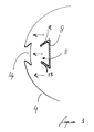
- Shown in Figure 3 is a cross sectional view from above of the portion of the side wall 4 of the container including the earthing strip 8.
- the earthing strip 8 includes a groove 11 having deformable side walls 12, 13. During manufacture the strip 8 is aligned with the corresponding ridge 14 on the inner face 6 of the side wall 4. The strip 8 is then urged in to contact with the ridge 14. This initially deforms the side walls 12, 13 outwards over the ridge 14 before they return to their original configuration so snapping the earthing strip 8 and ridge 14 into engagement.
- the container 1 In use the container 1 is filled with an explosive or flammable material such as petrol and the lid 2 closed and fastened. Before opening an electrically grounded earthing conductor is attached to the earthing strip 8. Since the earthing strip 8 is in electrical contact with the contents this discharges any static charge built up in the contents. The lid 2 can then be safely removed from the container 1.
- an explosive or flammable material such as petrol
- the lid 2 Before opening an electrically grounded earthing conductor is attached to the earthing strip 8. Since the earthing strip 8 is in electrical contact with the contents this discharges any static charge built up in the contents. The lid 2 can then be safely removed from the container 1.
- the earthing strip 8 is brass. In other embodiments other electrically conducting materials are possible.
- the container 1 is an oil drum. In alternative embodiments other containers are possible.
- the lid 2 is permanently connected to the side walls 4.
- the container is filled and emptied by means of a aperture (not shown) in the lid.
- the outer wall of the side wall also includes a ridge which can be snap fit into engagement with a corresponding groove or at least a portion of the outer portion of the earthing strip.
- the earthing strip 8 is sandwiched between the side wall and the base.
Landscapes
- Engineering & Computer Science (AREA)
- Mechanical Engineering (AREA)
- Chemical & Material Sciences (AREA)
- Chemical Kinetics & Catalysis (AREA)
- General Chemical & Material Sciences (AREA)
- Oil, Petroleum & Natural Gas (AREA)
- Closures For Containers (AREA)
- Coupling Device And Connection With Printed Circuit (AREA)
Applications Claiming Priority (2)
| Application Number | Priority Date | Filing Date | Title |
|---|---|---|---|
| GB0211685 | 2002-05-22 | ||
| GB0211685A GB0211685D0 (en) | 2002-05-22 | 2002-05-22 | A container |
Publications (2)
| Publication Number | Publication Date |
|---|---|
| EP1364882A2 true EP1364882A2 (fr) | 2003-11-26 |
| EP1364882A3 EP1364882A3 (fr) | 2004-02-04 |
Family
ID=9937114
Family Applications (1)
| Application Number | Title | Priority Date | Filing Date |
|---|---|---|---|
| EP02256797A Withdrawn EP1364882A3 (fr) | 2002-05-22 | 2002-09-30 | Conteneur |
Country Status (2)
| Country | Link |
|---|---|
| EP (1) | EP1364882A3 (fr) |
| GB (1) | GB0211685D0 (fr) |
Cited By (1)
| Publication number | Priority date | Publication date | Assignee | Title |
|---|---|---|---|---|
| WO2017021581A1 (fr) * | 2015-08-05 | 2017-02-09 | Zamora Fernando Martín | Conditionnement pour des fluides |
Family Cites Families (4)
| Publication number | Priority date | Publication date | Assignee | Title |
|---|---|---|---|---|
| JPS5993638A (ja) * | 1982-11-15 | 1984-05-30 | 東洋製罐株式会社 | 周状の側面継目を有する金属製容器 |
| GB2219270B (en) * | 1988-04-28 | 1992-05-06 | Harcostar Ltd | Containers |
| ATE236838T1 (de) * | 1995-08-14 | 2003-04-15 | Wuelfing & Hauck Gmbh & Co Kg | Innenauskleidung für flüssigkeits-, insbesondere benzintanks und damit hergestellter tank |
| DE20206435U1 (de) * | 2002-04-23 | 2002-08-08 | Schütz GmbH & Co. KGaA, 56242 Selters | Kunststoffaß |
-
2002
- 2002-05-22 GB GB0211685A patent/GB0211685D0/en not_active Ceased
- 2002-09-30 EP EP02256797A patent/EP1364882A3/fr not_active Withdrawn
Cited By (1)
| Publication number | Priority date | Publication date | Assignee | Title |
|---|---|---|---|---|
| WO2017021581A1 (fr) * | 2015-08-05 | 2017-02-09 | Zamora Fernando Martín | Conditionnement pour des fluides |
Also Published As
| Publication number | Publication date |
|---|---|
| GB0211685D0 (en) | 2002-07-03 |
| EP1364882A3 (fr) | 2004-02-04 |
Similar Documents
| Publication | Publication Date | Title |
|---|---|---|
| KR100944510B1 (ko) | 플라스틱 컨테이너 | |
| EP2806277B1 (fr) | Fermeture | |
| AU2586400A (en) | Explosion resistant aircraft cargo container | |
| US6265665B1 (en) | Gel-filled casing for an electrical connection and associated method | |
| US3138657A (en) | Splice insulating system | |
| WO2009136460A1 (fr) | Structure d’arrêt d’eau pour faisceau de câbles et procédé de formation de section d’arrêt d’eau | |
| US20090218132A1 (en) | device and method for universally leading through cables | |
| EP1364882A2 (fr) | Conteneur | |
| EP1387799A1 (fr) | Dispositif de transport et/ou de stockage | |
| US6540855B1 (en) | Method of interconnecting two elements | |
| CN1085416C (zh) | 筒形碱性电池 | |
| ES2106577T5 (es) | Procedimiento de fabricacion de un recipiente de material sintetico termoplastico para contener medios fluidos necesitados de seguridad. | |
| US4224385A (en) | Expandable battery case | |
| WO2001067527A2 (fr) | Pile seche au manganese | |
| EP1251572B1 (fr) | Boîte de batteries | |
| GB2219270A (en) | Containers of electrically insulating material | |
| EP0434655B1 (fr) | Système de fermeture et d'étanchéité réutilisable pour un récipient | |
| EP1346764B1 (fr) | Méthode de fabrication d'une connexion electroconductrice entre des composants métalliques comportant materiau de revetement non conducteur | |
| EP0620603B1 (fr) | Couvercle extérieur pour accumulateurs électriques muni des poignées | |
| US20070039962A1 (en) | Container lid removal facilitator | |
| KR20190087787A (ko) | 이차전지 및 이차전지 제조방법 | |
| AU638818B2 (en) | Electrical insulation apparatus | |
| AU2001241284A1 (en) | Battery of the type comprising a zinc can and a collector consisting of carbon for the cathode | |
| JPH0738136Y2 (ja) | 容器の口金 | |
| WO2001075995A1 (fr) | Batterie du type comprenant un boitier en zinc et un collecteur constitue de carbone pour la cathode |
Legal Events
| Date | Code | Title | Description |
|---|---|---|---|
| PUAI | Public reference made under article 153(3) epc to a published international application that has entered the european phase |
Free format text: ORIGINAL CODE: 0009012 |
|
| AK | Designated contracting states |
Kind code of ref document: A2 Designated state(s): AT BE BG CH CY CZ DE DK EE ES FI FR GB GR IE IT LI LU MC NL PT SE SK TR |
|
| AX | Request for extension of the european patent |
Extension state: AL LT LV MK RO SI |
|
| PUAL | Search report despatched |
Free format text: ORIGINAL CODE: 0009013 |
|
| AK | Designated contracting states |
Kind code of ref document: A3 Designated state(s): AT BE BG CH CY CZ DE DK EE ES FI FR GB GR IE IT LI LU MC NL PT SE SK TR |
|
| AX | Request for extension of the european patent |
Extension state: AL LT LV MK RO SI |
|
| RIC1 | Information provided on ipc code assigned before grant |
Ipc: 7B 65D 25/38 B Ipc: 7B 65D 8/04 A |
|
| 17P | Request for examination filed |
Effective date: 20040804 |
|
| AKX | Designation fees paid |
Designated state(s): AT BE BG CH CY CZ DE DK EE ES FI FR GB GR IE IT LI LU MC NL PT SE SK TR |
|
| 17Q | First examination report despatched |
Effective date: 20041006 |
|
| STAA | Information on the status of an ep patent application or granted ep patent |
Free format text: STATUS: THE APPLICATION IS DEEMED TO BE WITHDRAWN |
|
| 18D | Application deemed to be withdrawn |
Effective date: 20050419 |