EP1365105A1 - Reversierbare volumetrische Zahnradmaschine - Google Patents
Reversierbare volumetrische Zahnradmaschine Download PDFInfo
- Publication number
- EP1365105A1 EP1365105A1 EP03011045A EP03011045A EP1365105A1 EP 1365105 A1 EP1365105 A1 EP 1365105A1 EP 03011045 A EP03011045 A EP 03011045A EP 03011045 A EP03011045 A EP 03011045A EP 1365105 A1 EP1365105 A1 EP 1365105A1
- Authority
- EP
- European Patent Office
- Prior art keywords
- volumetric machine
- gear elements
- gear
- motor
- volumetric
- Prior art date
- Legal status (The legal status is an assumption and is not a legal conclusion. Google has not performed a legal analysis and makes no representation as to the accuracy of the status listed.)
- Withdrawn
Links
- 230000002441 reversible effect Effects 0.000 title claims abstract description 9
- 239000012530 fluid Substances 0.000 claims abstract description 32
- 230000002093 peripheral effect Effects 0.000 claims abstract description 9
- 230000003938 response to stress Effects 0.000 claims 1
- 239000008186 active pharmaceutical agent Substances 0.000 description 6
- 238000006073 displacement reaction Methods 0.000 description 5
- 238000010586 diagram Methods 0.000 description 4
- 230000003247 decreasing effect Effects 0.000 description 2
- 230000010349 pulsation Effects 0.000 description 2
- 101100361281 Caenorhabditis elegans rpm-1 gene Proteins 0.000 description 1
- 230000000712 assembly Effects 0.000 description 1
- 238000000429 assembly Methods 0.000 description 1
- 239000011324 bead Substances 0.000 description 1
- 230000002596 correlated effect Effects 0.000 description 1
- 238000012986 modification Methods 0.000 description 1
- 230000004048 modification Effects 0.000 description 1
- 238000011084 recovery Methods 0.000 description 1
- 125000006850 spacer group Chemical group 0.000 description 1
- XLYOFNOQVPJJNP-UHFFFAOYSA-N water Substances O XLYOFNOQVPJJNP-UHFFFAOYSA-N 0.000 description 1
Images




Classifications
-
- F—MECHANICAL ENGINEERING; LIGHTING; HEATING; WEAPONS; BLASTING
- F01—MACHINES OR ENGINES IN GENERAL; ENGINE PLANTS IN GENERAL; STEAM ENGINES
- F01C—ROTARY-PISTON OR OSCILLATING-PISTON MACHINES OR ENGINES
- F01C1/00—Rotary-piston machines or engines
- F01C1/08—Rotary-piston machines or engines of intermeshing engagement type, i.e. with engagement of co- operating members similar to that of toothed gearing
- F01C1/12—Rotary-piston machines or engines of intermeshing engagement type, i.e. with engagement of co- operating members similar to that of toothed gearing of other than internal-axis type
- F01C1/14—Rotary-piston machines or engines of intermeshing engagement type, i.e. with engagement of co- operating members similar to that of toothed gearing of other than internal-axis type with toothed rotary pistons
-
- B—PERFORMING OPERATIONS; TRANSPORTING
- B60—VEHICLES IN GENERAL
- B60C—VEHICLE TYRES; TYRE INFLATION; TYRE CHANGING; CONNECTING VALVES TO INFLATABLE ELASTIC BODIES IN GENERAL; DEVICES OR ARRANGEMENTS RELATED TO TYRES
- B60C25/00—Apparatus or tools adapted for mounting, removing or inspecting tyres
- B60C25/01—Apparatus or tools adapted for mounting, removing or inspecting tyres for removing tyres from or mounting tyres on wheels
- B60C25/05—Machines
- B60C25/132—Machines for removing and mounting tyres
- B60C25/135—Machines for removing and mounting tyres having a tyre support or a tool, movable along wheel axis
-
- B—PERFORMING OPERATIONS; TRANSPORTING
- B60—VEHICLES IN GENERAL
- B60C—VEHICLE TYRES; TYRE INFLATION; TYRE CHANGING; CONNECTING VALVES TO INFLATABLE ELASTIC BODIES IN GENERAL; DEVICES OR ARRANGEMENTS RELATED TO TYRES
- B60C25/00—Apparatus or tools adapted for mounting, removing or inspecting tyres
- B60C25/01—Apparatus or tools adapted for mounting, removing or inspecting tyres for removing tyres from or mounting tyres on wheels
- B60C25/05—Machines
- B60C25/132—Machines for removing and mounting tyres
- B60C25/135—Machines for removing and mounting tyres having a tyre support or a tool, movable along wheel axis
- B60C25/138—Machines for removing and mounting tyres having a tyre support or a tool, movable along wheel axis with rotary motion of tool or tyre support
-
- F—MECHANICAL ENGINEERING; LIGHTING; HEATING; WEAPONS; BLASTING
- F01—MACHINES OR ENGINES IN GENERAL; ENGINE PLANTS IN GENERAL; STEAM ENGINES
- F01C—ROTARY-PISTON OR OSCILLATING-PISTON MACHINES OR ENGINES
- F01C20/00—Control of, monitoring of, or safety arrangements for, machines or engines
- F01C20/02—Control of, monitoring of, or safety arrangements for, machines or engines specially adapted for several machines or engines connected in series or in parallel
-
- F—MECHANICAL ENGINEERING; LIGHTING; HEATING; WEAPONS; BLASTING
- F04—POSITIVE - DISPLACEMENT MACHINES FOR LIQUIDS; PUMPS FOR LIQUIDS OR ELASTIC FLUIDS
- F04C—ROTARY-PISTON, OR OSCILLATING-PISTON, POSITIVE-DISPLACEMENT MACHINES FOR LIQUIDS; ROTARY-PISTON, OR OSCILLATING-PISTON, POSITIVE-DISPLACEMENT PUMPS
- F04C2270/00—Control; Monitoring or safety arrangements
- F04C2270/01—Load
-
- F—MECHANICAL ENGINEERING; LIGHTING; HEATING; WEAPONS; BLASTING
- F04—POSITIVE - DISPLACEMENT MACHINES FOR LIQUIDS; PUMPS FOR LIQUIDS OR ELASTIC FLUIDS
- F04C—ROTARY-PISTON, OR OSCILLATING-PISTON, POSITIVE-DISPLACEMENT MACHINES FOR LIQUIDS; ROTARY-PISTON, OR OSCILLATING-PISTON, POSITIVE-DISPLACEMENT PUMPS
- F04C2270/00—Control; Monitoring or safety arrangements
- F04C2270/03—Torque
-
- F—MECHANICAL ENGINEERING; LIGHTING; HEATING; WEAPONS; BLASTING
- F04—POSITIVE - DISPLACEMENT MACHINES FOR LIQUIDS; PUMPS FOR LIQUIDS OR ELASTIC FLUIDS
- F04C—ROTARY-PISTON, OR OSCILLATING-PISTON, POSITIVE-DISPLACEMENT MACHINES FOR LIQUIDS; ROTARY-PISTON, OR OSCILLATING-PISTON, POSITIVE-DISPLACEMENT PUMPS
- F04C2270/00—Control; Monitoring or safety arrangements
- F04C2270/05—Speed
- F04C2270/052—Speed angular
Definitions
- the present invention relates to a fluid operated reversible volumetric machine, particularly, but not exclusively, for driving self-centring assemblies in tire assembling/disassembling machines.
- fluid operated volumetric machines are generally classified in three categories, each having specific structural and operative features, that depend on specific use-related requirements, namely: rotating vane machines, (axial as well as radial) piston machines, and gear, screw or special gearing machines.
- suction inlet E is set into communication with a working fluid (water, oil, air, etc.) source, not shown in Figure 1, the working fluid is sucked into housing C and delivered under pressure through the delivery outlet U.
- a pressurised working fluid be fed to inlet E, the volumetric machine becomes a motor with an output shaft formed by one of the axes of rotation of the pair of gear elements I.
- the volume of the spaces V between teeth D multiplied by the number of teeth gives the displacement of the volumetric machine that, as said, can be used as a pump or as a motor.
- Such a gear machine has, however, some disadvantageous shortcomings such as a relatively low yield, an excessive pulsations in the working fluid flow rate, a loud noise and high operation speeds within a very narrow range. Pulsations or volume variations in the working fluid and the noise are due to the fact that the number of gear teeth is very small generally speaking.
- the pair of gear elements is consistently subjected, in use, to a radial thrust, since the working fluid is subjected to different pressures at the suction inlet (fluid intake) and at the delivery outlet (fluid outlet) .
- a radial thrust is responsible for severe wear of the gears and low volumetric yield.
- each fluid conveyance spacer V at one gear element must be rotated through a 360° before being once again in meshing engagement with a tooth D of the other gear element. This means that it is inoperative throughout most of its circular path, i. e. it does not contribute to the working fluid displacement, as shown by the thrust or power diagram shown next to each gear element I 1 and I 2 in Fig. 1.
- the main object of the present invention is to obviate the shortcomings referred to above in connection with the prior art, by providing a reversible volumetric gear machine which, while having a simple structure typical of a machine of this type, makes it possible to vary its speed as a function of the load torque.
- Another object of the present invention is to provide a reversible volumetric gear machine with a high yield and very little wear in the gear elements.
- a further object of the present invention is to provide a tire disassembling equipment having a volumetric machine according to the present invention designed to be used as a motor..
- a reversible fluid operated machine comprising a receiving housing, at least two pairs of gear elements mounted for rotation in the receiving housing, so that each gear element is in meshing engagement with two adjoining gear elements equal thereto, an outer peripheral sequence with respect to the gear elements, of suction inlets alternating with as many delivery outlets formed in the receiving housing, and an inner peripheral sequence with respect to the gear elements, of delivery outlets, respectively, alternating with as many suction inlets formed in the receiving housing, each inner and outer sequence comprising a number of inlets and outlets equal to the number of gear elements.
- the volumetric machine comprises a receiving housing C and two, three or six pairs of gear elements I, respectively, mounted for rotation in the receiving housing C.
- Each gear element I is in a meshing engagement with two adjoining gear elements equal to it.
- an inlet opening E as well as an outlet opening U are provided for a working fluid fed from a fluid source P (Fig. 8).
- Opening U is arranged on the opposite side with respect to the inlet opening E with reference to the axes of its respective pair of gear elements.
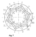
- the inlet openings E and outlet openings U are alternating according to a peripheral sequence outside the gear elements and a peripheral sequence inside the gear elements, as shown in the drawings.
- Each outer and inner sequence is formed by a number of inlet and outlet openings equal to the number of gear elements I.
- the various inlet openings E are in communication with each other because they are mutually connected by a manifold duct TE (Fig. 7) which is in communication with the fluid source P through an inlet mouth BE, whereas the various outlet openings U are in mutual communication through a collection duct TU leading to a working fluid recovery reservoir SE (Fig. 8) via an outlet opening BU, e.g by means of a standard circuit for a hydraulic unit driven by an electric motor,
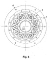
- Figs. 5 and 6 show some structural details of a volumetric machine according to the present invention, designed to operate as a motor M.
- each gear element I is keyed onto a respective rotating shaft RS, in turn mounted for rotation in an annular housing C.
- Shafts RS of the various gear elements I are arranged uniformly angularly spaced from each other along a circumference, and extend parallel to a driven shaft DS mounted for rotation on a pair of bearings K coaxially with housing C..
- the rotating shaft RS of one gear element I of each pair of gear elements also supports a respective pinion gear P keyed onto it, preferably located outside housing C, and in meshing engagement with a gear element G which is keyed onto driven shaft DS, whereby the rotation of the various pinion gears P results in the driven shaft DS (also referred to as the motor output shaft) being driven.
- a motor M such as that described above is particularly suitable for driving a hydraulic self-centring assembly GA on a tire assembling/disassembling machine MG (Fig. 9).
- the self-centring assembly GA on a tire assembling/disassembling machine MG has the drawback of being slow and at predetermined and fixed speeds it can operate at only two speeds of rotation at the most, both shortcomings being well known to the skilled in the art. Moreover, in some countries, legal restrictions exist on the power installed on board of tire assembling/disassembling machines, whereby monophase version of the motor is not permitted, and thus it would be necessary to resort to alternative costly solutions.
- a hydraulic motor M such as that described above is provided, which takes advantage of a hydraulic unit Cl comprising an electric motor ME, a pump PA drawing from a working fluid reservoir SE (Fig. 8) and designed to drive the self-centring assembly GA of a tire assembling/disassembling machine MG.
- the electric motor driven hydraulic unit is provided with air operated controls both to start electric motor ME and to drive the arrangement of valves usually provided in a tire assembling/disassembling machine MG.
- a hydraulic motor M In an embodiment of a hydraulic motor M according to the present invention, six pairs of gear elements I were used in mutual meshing engagement and with the axes of rotation of the gears arranged to be uniformly angularly spaced from one another along a circumference having a diameter of 121, 7 mm representing the middle line of an annular or ring-shaped housing C, as shown in Figs. 5 and 6.
- the pitch diameter of the gear elements I is 31.35 mm and the thrusting surface is 1.54 cm 2 , the working fluid must have is 65 bar.
- the power of the motor feeding pump will have to be increased accordingly.
- the electric motor With a 4 litre pump, the electric motor will need to have a power of about 0.5 kW.
- the six separate pairs of gear elements I will be sequentially fed by a delivery valve US -controlled by the pressure downstream of the motor M (i.e. a pressure correlated with the stress applied to motor M) as detected by a suitable pressure sensor SP which generates input signals to a programme control unit CU, e.g. consisting of an electronic card.
- valve US will feed a greater number of pairs of gear elements I as the control pressure builds up. Accordingly, the motor, when idle, will rotate at its maximum speed and its number of rotations per unit of time will be decreased as a function of the applied efford or stress (Figs. 10 and 11).
- each of the six outer inlet openings E 1 , E 3 , E 5 , E 7 , E 9 , E 11 , on one side, is connected only to one inner inlet opening E 2 , E 4 , E 6 , E 8 , E 10 , E 12 , respectively, and, on the other side, is fed by a respective feeding duct from a delivery valve US, whereas all the outlet openings are connected to a common duct TU communicating with a collection reservoir TU.
- Pump PA will thus become a variable fluid flow rate pump, e.g. in the range from a minimum of 4 litres to a maximum of 16 litres.. In this case the operating pressure will vary in a range from a maximum of 65 bar to a minimum of 16.5 bar, while keeping the power onboard the tire assembling/disassembling machine MG unchanged.
- the speed of the electric motor ME driving the pump PA is constantly controlled by the stress or force applied to shaft DS of motor M, thereby providing an intelligent system.
- a hydraulic motor M according to the present invention are particularly advantageous for a tire assembling/disassembling machine MG in that, if the motor speed were not decreased under stress, it would be necessary to provide a much greater power given by the maximum torque at the highest rpm on-board of a tire assembling/disassembling machine MG, which would be undesirable in a tire assembling/disassembling machine, if only because in a tire fitting step not enough time would be available for the bead to be inserted and fitted into the wheel-rim.
Landscapes
- Engineering & Computer Science (AREA)
- Mechanical Engineering (AREA)
- General Engineering & Computer Science (AREA)
- Rotary Pumps (AREA)
- Hydraulic Motors (AREA)
Applications Claiming Priority (2)
| Application Number | Priority Date | Filing Date | Title |
|---|---|---|---|
| IT2002VR000056A ITVR20020056A1 (it) | 2002-05-21 | 2002-05-21 | Macchina volumetrica reversibile |
| ITVR20020056 | 2002-05-21 |
Publications (1)
| Publication Number | Publication Date |
|---|---|
| EP1365105A1 true EP1365105A1 (de) | 2003-11-26 |
Family
ID=11462181
Family Applications (1)
| Application Number | Title | Priority Date | Filing Date |
|---|---|---|---|
| EP03011045A Withdrawn EP1365105A1 (de) | 2002-05-21 | 2003-05-19 | Reversierbare volumetrische Zahnradmaschine |
Country Status (5)
| Country | Link |
|---|---|
| US (1) | US20030219336A1 (de) |
| EP (1) | EP1365105A1 (de) |
| JP (1) | JP2004003483A (de) |
| CN (1) | CN1460607A (de) |
| IT (1) | ITVR20020056A1 (de) |
Cited By (3)
| Publication number | Priority date | Publication date | Assignee | Title |
|---|---|---|---|---|
| DE102005036711A1 (de) * | 2005-08-04 | 2006-07-27 | Daimlerchrysler Ag | Außenzahnradpumpe für Flüssigkeiten |
| CN104514699A (zh) * | 2013-09-30 | 2015-04-15 | 吴延勃 | 一种空压泵 |
| GB2523196A (en) * | 2014-02-18 | 2015-08-19 | Rolls Royce Controls & Data Services Ltd | Gear pump |
Families Citing this family (1)
| Publication number | Priority date | Publication date | Assignee | Title |
|---|---|---|---|---|
| KR101205379B1 (ko) | 2010-04-28 | 2012-11-28 | 삼성중공업 주식회사 | 정량 펌프 |
Citations (10)
| Publication number | Priority date | Publication date | Assignee | Title |
|---|---|---|---|---|
| FR569384A (fr) * | 1923-08-03 | 1924-04-11 | Perfectionnements aux moteurs hydrauliques à engrenages | |
| DE691592C (de) * | 1938-09-13 | 1940-05-31 | Westdeutsche Getriebewerke Boc | Umsteuerbarer Zahnradmotor fuer Druckluft |
| DE732701C (de) * | 1940-08-15 | 1943-03-10 | Eickhoff Geb | Zahnradmotor fuer Druckluftbetrieb |
| DE800097C (de) * | 1948-10-02 | 1950-09-01 | Heinrich Lanz Akt Ges | Raederpumpe mit mehreren Saug- und Druckstellen, insbesondere zum Foerdern von Schmieroel, z. B. fuer Mehrzylinder-Zweitaktmotoren |
| DE852658C (de) * | 1945-03-05 | 1952-10-16 | Sig Schweiz Industrieges | Regulierbares Pumpenaggregat |
| GB986830A (en) * | 1962-06-18 | 1965-03-24 | Thorvaid Loland | Improvements in rotor machines |
| US3627455A (en) * | 1970-02-05 | 1971-12-14 | Trw Inc | Multicycle self-balancing gear pump |
| JPS58204935A (ja) * | 1982-05-21 | 1983-11-29 | Kubota Ltd | 歯車内燃機関の燃焼室 |
| US5196772A (en) * | 1990-09-05 | 1993-03-23 | Hofmann Maschinenbau Gmbh | Apparatus for fitting tires on wheels |
| EP1040941A2 (de) * | 1999-04-02 | 2000-10-04 | BUTLER ENGINEERING & MARKETING S.r.l. | Reifenwechselvorrichtung für Nutzfahrzeuge |
Family Cites Families (7)
| Publication number | Priority date | Publication date | Assignee | Title |
|---|---|---|---|---|
| US2737020A (en) * | 1949-10-25 | 1956-03-06 | Oliver Iron And Steel Corp | Rotary pump and motor hydraulic transmission |
| US2765749A (en) * | 1955-03-09 | 1956-10-09 | Roper Corp Geo D | Fluid pump or motor |
| US3067691A (en) * | 1959-12-21 | 1962-12-11 | Reiners & Wiggermann Getriebe | Controllable hydraulic machine of the triple-gear type |
| US4530388A (en) * | 1983-06-30 | 1985-07-23 | Krueger Harold L | Tire handling device |
| US4578020A (en) * | 1984-01-30 | 1986-03-25 | Josef Bartos | Hydraulic motor |
| US4635439A (en) * | 1985-04-11 | 1987-01-13 | Caterpillar Industrial Inc. | Fluid operated system control |
| DE3623066A1 (de) * | 1986-07-09 | 1988-01-28 | Rexroth Mannesmann Gmbh | Schaltungsanordnung zur drehzahlregelung einer an eine leitung mit eingepraegtem druck angeschlossenen hydrostatischen maschine |
-
2002
- 2002-05-21 IT IT2002VR000056A patent/ITVR20020056A1/it unknown
-
2003
- 2003-05-19 EP EP03011045A patent/EP1365105A1/de not_active Withdrawn
- 2003-05-20 JP JP2003141817A patent/JP2004003483A/ja active Pending
- 2003-05-21 US US10/442,072 patent/US20030219336A1/en not_active Abandoned
- 2003-05-21 CN CN03136299.0A patent/CN1460607A/zh active Pending
Patent Citations (10)
| Publication number | Priority date | Publication date | Assignee | Title |
|---|---|---|---|---|
| FR569384A (fr) * | 1923-08-03 | 1924-04-11 | Perfectionnements aux moteurs hydrauliques à engrenages | |
| DE691592C (de) * | 1938-09-13 | 1940-05-31 | Westdeutsche Getriebewerke Boc | Umsteuerbarer Zahnradmotor fuer Druckluft |
| DE732701C (de) * | 1940-08-15 | 1943-03-10 | Eickhoff Geb | Zahnradmotor fuer Druckluftbetrieb |
| DE852658C (de) * | 1945-03-05 | 1952-10-16 | Sig Schweiz Industrieges | Regulierbares Pumpenaggregat |
| DE800097C (de) * | 1948-10-02 | 1950-09-01 | Heinrich Lanz Akt Ges | Raederpumpe mit mehreren Saug- und Druckstellen, insbesondere zum Foerdern von Schmieroel, z. B. fuer Mehrzylinder-Zweitaktmotoren |
| GB986830A (en) * | 1962-06-18 | 1965-03-24 | Thorvaid Loland | Improvements in rotor machines |
| US3627455A (en) * | 1970-02-05 | 1971-12-14 | Trw Inc | Multicycle self-balancing gear pump |
| JPS58204935A (ja) * | 1982-05-21 | 1983-11-29 | Kubota Ltd | 歯車内燃機関の燃焼室 |
| US5196772A (en) * | 1990-09-05 | 1993-03-23 | Hofmann Maschinenbau Gmbh | Apparatus for fitting tires on wheels |
| EP1040941A2 (de) * | 1999-04-02 | 2000-10-04 | BUTLER ENGINEERING & MARKETING S.r.l. | Reifenwechselvorrichtung für Nutzfahrzeuge |
Non-Patent Citations (1)
| Title |
|---|
| PATENT ABSTRACTS OF JAPAN vol. 008, no. 050 (M - 281) 7 March 1984 (1984-03-07) * |
Cited By (3)
| Publication number | Priority date | Publication date | Assignee | Title |
|---|---|---|---|---|
| DE102005036711A1 (de) * | 2005-08-04 | 2006-07-27 | Daimlerchrysler Ag | Außenzahnradpumpe für Flüssigkeiten |
| CN104514699A (zh) * | 2013-09-30 | 2015-04-15 | 吴延勃 | 一种空压泵 |
| GB2523196A (en) * | 2014-02-18 | 2015-08-19 | Rolls Royce Controls & Data Services Ltd | Gear pump |
Also Published As
| Publication number | Publication date |
|---|---|
| US20030219336A1 (en) | 2003-11-27 |
| CN1460607A (zh) | 2003-12-10 |
| ITVR20020056A1 (it) | 2003-11-21 |
| ITVR20020056A0 (it) | 2002-05-21 |
| JP2004003483A (ja) | 2004-01-08 |
Similar Documents
| Publication | Publication Date | Title |
|---|---|---|
| CN104379934B (zh) | 具有用于轴向推力平衡的液压系统、带有螺旋齿的齿轮泵或液压齿轮电动机 | |
| US7588431B2 (en) | Variable capacity pump/motor | |
| US4355542A (en) | Scavenging pump | |
| US7179070B2 (en) | Variable capacity pump/motor | |
| JP2019511672A (ja) | 遠心式圧縮段と容積形圧縮段との組合せを有する一体型ギア圧縮機 | |
| US20030219336A1 (en) | Reversible volumetric machine | |
| US10563654B2 (en) | Pump-motor combination having a single common rotor shaft | |
| GB2114228A (en) | A rotary gas-compressor | |
| US8292597B2 (en) | High-speed gear pump | |
| US8226382B2 (en) | Feed pump in a motor vehicle | |
| HK1062704A (en) | Reversible gearwheels volumetric machine | |
| CN112513464A (zh) | 流体输送装置 | |
| JPH03121346A (ja) | ミッションのオイル通路 | |
| JP2000074096A (ja) | 駆動連結装置 | |
| JPH02185682A (ja) | ジェロータポンプ | |
| GB2110759A (en) | Rotary positive-displacement fluid-machines | |
| CN213838887U (zh) | 一种并联集成式泛摆线齿轮泵装置 | |
| HK1059765A (en) | Reversible volumetric machine | |
| CN223317998U (zh) | 柱塞泵和柱塞泵组件 | |
| CN216477705U (zh) | 柱塞泵 | |
| CN216621234U (zh) | 配胶机进料检测机构 | |
| US11248602B2 (en) | Fluid delivery device with a forepump, a main pump, and bypass line with a check valve | |
| CN109209896A (zh) | 高扬程扬水装置 | |
| JPS59589A (ja) | 遠心多段ポンプ | |
| EP0365805A2 (de) | Vorrichtung zur Strömungsregelung und eine Hochdruckpumpe |
Legal Events
| Date | Code | Title | Description |
|---|---|---|---|
| PUAI | Public reference made under article 153(3) epc to a published international application that has entered the european phase |
Free format text: ORIGINAL CODE: 0009012 |
|
| AK | Designated contracting states |
Kind code of ref document: A1 Designated state(s): AT BE BG CH CY CZ DE DK EE ES FI FR GB GR HU IE IT LI LU MC NL PT RO SE SI SK TR |
|
| AX | Request for extension of the european patent |
Extension state: AL LT LV MK |
|
| AKX | Designation fees paid | ||
| REG | Reference to a national code |
Ref country code: DE Ref legal event code: 8566 |
|
| REG | Reference to a national code |
Ref country code: HK Ref legal event code: DE Ref document number: 1062704 Country of ref document: HK |
|
| STAA | Information on the status of an ep patent application or granted ep patent |
Free format text: STATUS: THE APPLICATION IS DEEMED TO BE WITHDRAWN |
|
| 18D | Application deemed to be withdrawn |
Effective date: 20040527 |
|
| REG | Reference to a national code |
Ref country code: HK Ref legal event code: WD Ref document number: 1062704 Country of ref document: HK |