EP1365108A2 - Aube pour un moteur à turbine à gaz et procedé de fabrication d'une telle aube - Google Patents
Aube pour un moteur à turbine à gaz et procedé de fabrication d'une telle aube Download PDFInfo
- Publication number
- EP1365108A2 EP1365108A2 EP03253238A EP03253238A EP1365108A2 EP 1365108 A2 EP1365108 A2 EP 1365108A2 EP 03253238 A EP03253238 A EP 03253238A EP 03253238 A EP03253238 A EP 03253238A EP 1365108 A2 EP1365108 A2 EP 1365108A2
- Authority
- EP
- European Patent Office
- Prior art keywords
- blade
- shank
- dovetail
- cooling cavity
- width
- Prior art date
- Legal status (The legal status is an assumption and is not a legal conclusion. Google has not performed a legal analysis and makes no representation as to the accuracy of the status listed.)
- Ceased
Links
- 238000000034 method Methods 0.000 title claims abstract description 16
- 238000004519 manufacturing process Methods 0.000 title claims description 8
- 238000001816 cooling Methods 0.000 claims abstract description 122
- 230000007704 transition Effects 0.000 claims abstract description 71
- 238000000576 coating method Methods 0.000 claims abstract description 41
- 239000011248 coating agent Substances 0.000 claims abstract description 40
- 230000007613 environmental effect Effects 0.000 claims abstract description 25
- 230000003647 oxidation Effects 0.000 claims abstract description 22
- 238000007254 oxidation reaction Methods 0.000 claims abstract description 22
- 238000004891 communication Methods 0.000 claims description 10
- 239000007789 gas Substances 0.000 description 25
- 230000035882 stress Effects 0.000 description 7
- 239000000919 ceramic Substances 0.000 description 6
- 239000012809 cooling fluid Substances 0.000 description 6
- 238000005336 cracking Methods 0.000 description 6
- 230000008646 thermal stress Effects 0.000 description 4
- 239000002002 slurry Substances 0.000 description 3
- 229910000951 Aluminide Inorganic materials 0.000 description 2
- 239000002184 metal Substances 0.000 description 2
- 239000000203 mixture Substances 0.000 description 2
- 230000002028 premature Effects 0.000 description 2
- OKTJSMMVPCPJKN-UHFFFAOYSA-N Carbon Chemical compound [C] OKTJSMMVPCPJKN-UHFFFAOYSA-N 0.000 description 1
- 239000000567 combustion gas Substances 0.000 description 1
- 238000010276 construction Methods 0.000 description 1
- 238000005137 deposition process Methods 0.000 description 1
- 239000000446 fuel Substances 0.000 description 1
- 229910002804 graphite Inorganic materials 0.000 description 1
- 239000010439 graphite Substances 0.000 description 1
- 239000007788 liquid Substances 0.000 description 1
- 239000000463 material Substances 0.000 description 1
- 238000005297 material degradation process Methods 0.000 description 1
- 238000005192 partition Methods 0.000 description 1
- 239000007787 solid Substances 0.000 description 1
- 239000012808 vapor phase Substances 0.000 description 1
Images



Classifications
-
- F—MECHANICAL ENGINEERING; LIGHTING; HEATING; WEAPONS; BLASTING
- F01—MACHINES OR ENGINES IN GENERAL; ENGINE PLANTS IN GENERAL; STEAM ENGINES
- F01D—NON-POSITIVE DISPLACEMENT MACHINES OR ENGINES, e.g. STEAM TURBINES
- F01D5/00—Blades; Blade-carrying members; Heating, heat-insulating, cooling or antivibration means on the blades or the members
- F01D5/02—Blade-carrying members, e.g. rotors
- F01D5/08—Heating, heat-insulating or cooling means
- F01D5/081—Cooling fluid being directed on the side of the rotor disc or at the roots of the blades
-
- F—MECHANICAL ENGINEERING; LIGHTING; HEATING; WEAPONS; BLASTING
- F01—MACHINES OR ENGINES IN GENERAL; ENGINE PLANTS IN GENERAL; STEAM ENGINES
- F01D—NON-POSITIVE DISPLACEMENT MACHINES OR ENGINES, e.g. STEAM TURBINES
- F01D5/00—Blades; Blade-carrying members; Heating, heat-insulating, cooling or antivibration means on the blades or the members
- F01D5/02—Blade-carrying members, e.g. rotors
- F01D5/08—Heating, heat-insulating or cooling means
- F01D5/085—Heating, heat-insulating or cooling means cooling fluid circulating inside the rotor
- F01D5/087—Heating, heat-insulating or cooling means cooling fluid circulating inside the rotor in the radial passages of the rotor disc
-
- F—MECHANICAL ENGINEERING; LIGHTING; HEATING; WEAPONS; BLASTING
- F01—MACHINES OR ENGINES IN GENERAL; ENGINE PLANTS IN GENERAL; STEAM ENGINES
- F01D—NON-POSITIVE DISPLACEMENT MACHINES OR ENGINES, e.g. STEAM TURBINES
- F01D5/00—Blades; Blade-carrying members; Heating, heat-insulating, cooling or antivibration means on the blades or the members
- F01D5/12—Blades
- F01D5/14—Form or construction
- F01D5/147—Construction, i.e. structural features, e.g. of weight-saving hollow blades
-
- F—MECHANICAL ENGINEERING; LIGHTING; HEATING; WEAPONS; BLASTING
- F01—MACHINES OR ENGINES IN GENERAL; ENGINE PLANTS IN GENERAL; STEAM ENGINES
- F01D—NON-POSITIVE DISPLACEMENT MACHINES OR ENGINES, e.g. STEAM TURBINES
- F01D5/00—Blades; Blade-carrying members; Heating, heat-insulating, cooling or antivibration means on the blades or the members
- F01D5/12—Blades
- F01D5/14—Form or construction
- F01D5/18—Hollow blades, i.e. blades with cooling or heating channels or cavities; Heating, heat-insulating or cooling means on blades
- F01D5/187—Convection cooling
-
- F—MECHANICAL ENGINEERING; LIGHTING; HEATING; WEAPONS; BLASTING
- F05—INDEXING SCHEMES RELATING TO ENGINES OR PUMPS IN VARIOUS SUBCLASSES OF CLASSES F01-F04
- F05B—INDEXING SCHEME RELATING TO WIND, SPRING, WEIGHT, INERTIA OR LIKE MOTORS, TO MACHINES OR ENGINES FOR LIQUIDS COVERED BY SUBCLASSES F03B, F03D AND F03G
- F05B2240/00—Components
- F05B2240/80—Platforms for stationary or moving blades
- F05B2240/801—Platforms for stationary or moving blades cooled platforms
-
- F—MECHANICAL ENGINEERING; LIGHTING; HEATING; WEAPONS; BLASTING
- F05—INDEXING SCHEMES RELATING TO ENGINES OR PUMPS IN VARIOUS SUBCLASSES OF CLASSES F01-F04
- F05D—INDEXING SCHEME FOR ASPECTS RELATING TO NON-POSITIVE-DISPLACEMENT MACHINES OR ENGINES, GAS-TURBINES OR JET-PROPULSION PLANTS
- F05D2240/00—Components
- F05D2240/80—Platforms for stationary or moving blades
- F05D2240/81—Cooled platforms
Definitions
- This invention relates generally to gas turbine engines, and more specifically to turbine blades used with gas turbine engines.
- At least some known gas turbine engines include a core engine having, in serial flow arrangement, a high pressure compressor which compresses airflow entering the engine, a combustor which burns a mixture of fuel and air, and a turbine which includes a plurality of rotor blades that extract rotational energy from airflow exiting the combustor the burned mixture. Because the turbine is subjected to high temperature airflow exiting the combustor, turbine components are cooled to reduce thermal stresses that may be induced by the high temperature airflow.
- the rotating blades include hollow airfoils that are supplied cooling air through cooling circuits.
- the airfoils include a cooling cavity bounded by sidewalls that define the cooling cavity. Cooling of engine components, such as components of the high pressure turbine, is necessary due to thermal stress limitations of materials used in construction of such components. Typically, cooling air is extracted air from an outlet of the compressor and the cooling air is used to cool, for example, turbine airfoils. The cooling air, after cooling the turbine airfoils, re-enters the gas path downstream of the combustor.
- At least some known turbine airfoils include cooling circuits which channel cooling air flows for cooling the airfoil. More particularly, internal cavities within the airfoil define flow paths for directing the cooling air. Such cavities may define, for example, a serpentine shaped path having multiple passes. Cooling air is directed through a root portion of the airfoil into the serpentine shaped path. In at least some known airfoil designs, an abrupt transition extends between the root portion and the airfoil portion to increase the cross-sectional area of the cooling cavity to facilitate increasing the volume of cooling air entering the airfoil portion. Because thermal stresses may be induced into the internal cavities, walls defining the cavities may be coated with a environmental coating to facilitate preventing oxidation within the cooling cavity. Because of the geometry of the cooling passages, during coating process, the coating is also deposited within the root portion of the airfoil.
- At least some known blades are coated with a layer of environmental coating that has a thickness approximately equal to 0.001 inches. Applying the environmental coating with such a thickness prevents oxidation of the cavity walls and facilitates the airfoil withstanding thermal and mechanical stresses that may be induced within the higher operating temperature areas of the blade.
- the coating is applied at a greater thickness, the combination of the increased thickness of the environmental coating and the abrupt transition within the dovetail may cause premature cracking in the root portion of the airfoil as stresses are induced into the transition area of the dovetail. Over time, continued operation may lead a premature failure of the blade within the engine.
- a method for manufacturing a blade for a gas turbine engine includes an airfoil, a platform, a shank, and a dovetail, wherein the platform extends between the airfoil and the shank, the shank extends between the dovetail and the platform, and the dovetail includes at least one tang for securing the blade within the engine.
- the method comprises defining a cooling cavity in the blade that extends through the airfoil the platform, the shank, and the dovetail, wherein the portion of the cavity defined within the dovetail includes a root passage portion having a first width, and a transition portion extends between the root passage and the portion of the cavity defined within the shank, and wherein the portion of the cavity defined within the shank has a second width that is larger than the root passage first width.
- the method also comprises coating at least a portion of an inner surface of the blade that defines the cooling cavity with a layer of an oxidation resistant environmental coating.
- a blade for a gas turbine engine in another aspect, includes a platform, a shank extending from the platform, and a dovetail extending between an end of the blade and the shank for mounting the blade within the gas turbine engine, wherein the dovetail includes at least one tang.
- the blade also includes an airfoil including a first sidewall and a second sidewall extending in radial span between the platform and a blade tip, and a cooling cavity defined within the blade by the dovetail, the shank, the platform, and the airfoil, the cooling cavity including a dovetail portion defined within the dovetail, a shank portion defined within the shank and the platform, and an airfoil portion defined within the airfoil, wherein the shank portion is coupled in flow communication between the airfoil portion and the dovetail portion, the dovetail portion includes a root passage and a transition passage, the root passage including a first width, the shank portion including a second width larger than the first width, and the transition passage coupled between the root passage and the shank portion.
- a gas turbine engine including a plurality of blades.
- Each blade includes an airfoil, a shank, and a platform extending therebetween.
- Each blade also includes a cooling cavity, and a dovetail including at least one tang configured to secure the blade within the engine.
- the shank extends between the platform and the dovetail, the cooling cavity is defined by the airfoil, the platform, the shank, and the dovetail, and includes a dovetail portion, a shank portion, and an airfoil portion coupled in flow communication.
- the dovetail portion includes a root passage including a first width, and a transition passage.
- the shank portion includes a second width that is larger than the root passage first width, and the transition passage is tapered between the root passage and the shank portion.
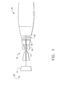
- Figure 1 is a schematic illustration of a gas turbine engine 10 including a fan assembly 12, a high pressure compressor 14, and a combustor 16.
- Engine 10 also includes a high pressure turbine 18 and a low pressure turbine 20.
- Engine 10 has an intake side 28 and an exhaust side 30.
- engine 10 is a CFM-56 engine commercially available from CFM International, Cincinnati, Ohio.
- Airflow from combustor 16 drives turbines 18 and 20, and turbine 20 drives fan assembly 12.
- Turbine 18 drives high pressure compressor 14.
- FIG 2 is a perspective view of a rotor assembly 40 that may be used with a gas turbine engine, such as gas turbine engine 10 (shown in Figure 1).
- Assembly 40 includes a plurality of rotor blades 42 mounted within a rotor disk 44.
- blades 42 form a high-pressure turbine rotor blade stage (not shown) of gas turbine engine 10.
- Rotor blades 42 extend radially outward from rotor disk 44, and each includes an airfoil 50, a platform 52, a shank 54, and a dovetail 56.
- Each airfoil 50 includes first sidewall 60 and a second sidewall 62.
- First sidewall 60 is convex and defines a suction side of airfoil 50
- second sidewall 62 is concave and defines a pressure side of airfoil 50.
- Sidewalls 60 and 62 are joined at a leading edge 64 and at an axially-spaced trailing edge 66 of airfoil 50. More specifically, airfoil trailing edge 66 is spaced chord-wise and downstream from airfoil leading edge 64.
- First and second sidewalls 60 and 62 extend longitudinally or radially outward in span from a blade root 68 positioned adjacent platform 52, to an airfoil tip 70.
- Airfoil tip 70 defines a radially outer boundary of an internal cooling chamber (not shown in Figure 2).
- the cooling chamber is bounded within airfoil 50 between sidewalls 60 and 62, and extends through platform 52 and through shank 54 and into dovetail 56. More specifically, airfoil 50 includes an inner surface (not shown in Figure 2) and an outer surface 74, and the cooling chamber is defined by the airfoil inner surface.
- Platform 52 extends between airfoil 50 and shank 54 such that each airfoil 50 extends radially outward from each respective platform 52.
- Shank 54 extends radially inwardly from platform 52 to dovetail 56.
- Dovetail 56 extends radially inwardly from shank 54 and facilitates securing rotor blade 42 to rotor disk 44. More specifically, each dovetail 56 includes at least one tang 80 that extends radially outwardly from dovetail 56 and facilitates mounting each dovetail 56 in a respective dovetail slot 82.
- dovetail 56 includes an upper pair of blade tangs 84, and a lower pair of blade tangs 86.
- FIG 3 is an exemplary partial leading edge cross-sectional view of rotor blade rotor blade 42.
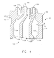
- Figure 4 is an exemplary partial side cross-sectional view of rotor blade 42.
- Figure 5 is an exemplary side cross-sectional view of a portion of a known rotor blade 100.
- Each blade 42 includes platform 52, shank 54, and dovetail 56. As described above, shank 54 extends between platform 52 and dovetail 56, and dovetail 56 extends radially inwardly from shank 54 to a radially inner end 101 of blade 42.
- Platform 52, shank 54, dovetail 56, and airfoil 50 are hollow, and define a cooling cavity 102 that extends therethrough.
- cooling cavity 102 is bounded within rotor blade 42 by an inner surface 104 of blade 42.
- Cooling cavity 102 includes a plurality of inner walls 106 which partition cooling cavity 102 into a plurality of cooling chambers 108.
- the geometry and interrelationship of chambers 108 to walls 106 varies with the intended use of blade 42.
- inner walls 106 are cast integrally with airfoil 50.
- Blade cooling cavity 102 also includes a dovetail portion 112, a shank portion 114, and an airfoil portion 116 coupled together in flow communication such that cooling fluid supplied to cooling cavity dovetail portion 112 is routed through portions 112 and 114 and into cooling cavity airfoil portion 116.
- Cooling cavity dovetail portion 112 includes a root passage section 120 and a transition passage section 122 coupled in flow communication. More specifically, root passage section 120 includes a plurality of root passages 124 that extend between blade end 101 and transition passage section 122, and transition passage section 122 extends between root passage section 120 and shank portion 114.
- Root passage section 120 has a substantially constant width D R measured between a suction sidewall 132 and a pressure sidewall 134 of cooling cavity 102. More specifically, width D R is substantially constant for a length 136 measured between a radially inner end 138 of root passage section 120 and a radially outer end 140 of root passage section 120. Root passage section radially inner end 138 is adjacent a cooling cavity throat 141 and root passage section radially outer end 140 is adjacent transition passage section 122. Cooling cavity throat 141 is defined at blade end 101 between lower blade tangs 86, and root passage section radially outer end 140 is defined between upper blade tangs 84. Accordingly, sidewalls 132 and 134 are substantially parallel within root passage section 120.
- Transition passage section 122 gradually tapers outwardly from root passage section 120 to cooling cavity shank portion 114, which has a width D S that is larger than root passage section width D R . Accordingly, a width D T of transition passage section 122 is variable between a radially inner end 142 and a radially outer end 144 of transition passage section 122. Variable transition passage section width D T is larger than root passage section width D R through transition passage section 122, and is equal shank portion width D S at transition passage radially outer end 144. Transition passage section 122 has a length 146 measured between measured between transition passage section ends 142 and 144.
- transition passage section length 146 and an arcuate interface 156, formed with a pre-defined radius and defined between transition passage section 122 and root section passage 120, enables transition passage section 122 to taper gradually outward between root section 120 and shank portion 114. Furthermore, transition passage section length 146 enables an arcuate interface 170 to be defined between transition passage section 122 and shank portion 114.
- Rotor blade 100 is known and is substantially similar to blade 42. Accordingly, blade 100 includes platform 52, shank 54, and dovetail 56. Additionally, blade 100 includes a cooling cavity 202 that is substantially similar to cooling cavity 102, and is bounded by an inner surface 204 of blade 100. Blade cooling cavity 202 also includes airfoil portion 116, a dovetail portion 212, and shank portion 114 coupled together in flow communication such that cooling fluid supplied to cooling cavity dovetail portion 212 is routed through portions 212 and 114 into cooling cavity airfoil portion 116. Cooling cavity dovetail portion 212 includes a root passage section 220 and a transition passage section 222 coupled in flow communication. More specifically, root passage section 220 extends between blade end 101 and transition passage section 222, and transition passage section 222 extends between root passage section 220 and shank portion 114.
- Root passage section radially inner end 138 is adjacent cooling cavity throat 141 and root passage section radially outer end 140 is adjacent transition passage section 222.
- Cooling cavity throat 138 is defined at blade end 101 between lower blade tangs 86, and root passage section radially outer end 140 is defined between upper blade tangs 84.
- Transition passage section 222 expands outwardly from root passage section 120 to cooling cavity shank portion 114. Accordingly, a width 240 of transition passage section 222 is variable between a radially inner end 242 and a radially outer end 244 of transition passage section 222. Transition passage section width 240 is larger than root passage section width D R . Transition passage section 222 has a length 246 measured between measured between transition passage section ends 242 and 244. Because length 246 is less than transition passage length 146, transition passage section 222 expands abruptly outwardly from root passage section 222 to shank portion 114, such that transition passage section width 240 is equal to shank portion width D S at transition passage section end 244.
- a lower corner 256 is formed between transition passage section 222 and root passage section 220, and an upper corner 258 is formed between transition passage section 222 and shank portion 114. Furthermore, because length 246 is less than transition passage length 146, upper corner 258 is defined between upper blade tangs 84.
- airfoil inner surface 104 is coated with a layer of an oxidation resistive environmental coating.
- the oxidation resistive environmental coating is an aluminide coating commercially available from Howmet Thermatech, Whitehall, Michigan.
- an oxidation resistive environmental coating is applied to airfoil inner surface by a vapor phase aluminide deposition process.
- the combination of arcuate interfaces 156 and 170, and transition passage section 122 enable the oxidation resistive environmental coating to be applied at thickness' that are greater than those acceptable within blade 100. Specifically, within blade 100 it is known to limit the thickness of environmental coating to less than 0.001 inches.
- the coating may be applied to a thickness of 0.015 inches.
- the increased thickness enables manufacturing coating controls that are used to limit a thickness of the coating applied to blade 100 to be reduced within blade 42, such that an overall manufacturing cost of blade 42 is reduced in comparison to blade 100.
- a core (not shown) is cast into blade 42.
- the core is fabricated by injecting a liquid ceramic and graphite slurry into a core die (not shown). The slurry is heated to form a solid ceramic airfoil core.
- the airfoil core is suspended in an airfoil die (not shown) and hot wax is injected into the airfoil die to surround the ceramic airfoil core. The hot wax solidifies and forms an airfoil (not shown) with the ceramic core suspended in the airfoil.
- the wax airfoil with the ceramic core is then dipped in a ceramic slurry and allowed to dry. This procedure is repeated several times such that a shell is formed over the wax airfoil.
- the wax is then melted out of the shell leaving a mold with a core suspended inside, and into which molten metal is poured. After the metal has solidified the shell is broken away and the core removed.
- cooling fluid is supplied into blade 42 through cooling cavity root passage section 120.
- the cooling fluid is supplied to blade 42 from a compressor, such as compressor 14 (shown in Figure 1). Cooling fluid entering blade dovetail 56 is channeled through root passage section 122 and through transition passage section 122 into cooling cavity shank portion 122. The cooling fluid is then channeled into cooling chambers 108 defined within cooling cavity airfoil portion 116. As hot combustion gases impinge upon blade 42, an operating temperature of blade internal surface 104. The oxidation resistive environmental coating facilitates reducing oxidation of blade internal surface 104 despite the increased operating temperature.
- arcuate interfaces 156 and 170 facilitate limiting cracking of the oxidation resistive environmental coating within blade dovetail 56 and, thus, extends a useful life of blade 42. Furthermore, during operation, arcuate interfaces 156 and 170 facilitate reducing operating stresses that may be induced into dovetail 56 in comparison to corners 256 and 258 of blade 100, and thus also facilitates extending a useful life of blade 42.
- the above-described blade is cost-effective and highly reliable.
- the blade includes a cooling cavity defined at least partially within a dovetail portion of the blade.
- the cooling cavity defined within the dovetail includes arcuate transitions between the various portions of the cooling cavity.
- the arcuate transitions facilitate reducing operating stresses that may be induced into the dovetail in comparison to known rotor blades.
- the arcuate transitions enable a thicker layer of oxidation resistive environmental coating to be applied to an inner surface of the blade in comparison to known blades.
- the arcuate transitions facilitate reduced cracking of the thicker layer of coating within the blade dovetail.
- the geometry design of the blade, in combination with the environmental coating facilitates maintaining thermal fatigue life and extending a useful life of the airfoil in a cost-effective and reliable manner.
Landscapes
- Engineering & Computer Science (AREA)
- Mechanical Engineering (AREA)
- General Engineering & Computer Science (AREA)
- Architecture (AREA)
- Turbine Rotor Nozzle Sealing (AREA)
Applications Claiming Priority (2)
| Application Number | Priority Date | Filing Date | Title |
|---|---|---|---|
| US155452 | 1993-11-19 | ||
| US10/155,452 US6932570B2 (en) | 2002-05-23 | 2002-05-23 | Methods and apparatus for extending gas turbine engine airfoils useful life |
Publications (2)
| Publication Number | Publication Date |
|---|---|
| EP1365108A2 true EP1365108A2 (fr) | 2003-11-26 |
| EP1365108A3 EP1365108A3 (fr) | 2004-10-06 |
Family
ID=29400578
Family Applications (1)
| Application Number | Title | Priority Date | Filing Date |
|---|---|---|---|
| EP03253238A Ceased EP1365108A3 (fr) | 2002-05-23 | 2003-05-23 | Aube pour un moteur à turbine à gaz et procedé de fabrication d'une telle aube |
Country Status (4)
| Country | Link |
|---|---|
| US (1) | US6932570B2 (fr) |
| EP (1) | EP1365108A3 (fr) |
| JP (1) | JP4458772B2 (fr) |
| CN (1) | CN100572757C (fr) |
Cited By (9)
| Publication number | Priority date | Publication date | Assignee | Title |
|---|---|---|---|---|
| EP1605137A1 (fr) * | 2004-05-27 | 2005-12-14 | United Technologies Corporation | Aube de rotor refroidie |
| EP1798374A2 (fr) | 2005-12-15 | 2007-06-20 | United Technologies Corporation | Aube de turbine refroidie |
| EP1832712A1 (fr) * | 2006-03-08 | 2007-09-12 | Snecma | Aube mobile de turbomachine à cavité commune d'alimentation en air de refroidissement |
| EP2808418A3 (fr) * | 2013-05-29 | 2015-03-11 | Mitsubishi Hitachi Power Systems, Ltd. | Procédé de fabrication d'aube de turbine à gaz et ladite aube |
| EP2896786A1 (fr) * | 2014-01-20 | 2015-07-22 | Honeywell International Inc. | Ensembles de rotor de turbine avec des cavités de fente améliorées |
| US9243502B2 (en) | 2012-04-24 | 2016-01-26 | United Technologies Corporation | Airfoil cooling enhancement and method of making the same |
| US9296039B2 (en) | 2012-04-24 | 2016-03-29 | United Technologies Corporation | Gas turbine engine airfoil impingement cooling |
| US9664051B2 (en) | 2011-06-16 | 2017-05-30 | Siemens Aktiengesellschaft | Rotor blade root section with cooling passage and method for supplying cooling fluid to a rotor blade |
| FR3087479A1 (fr) * | 2018-10-23 | 2020-04-24 | Safran Aircraft Engines | Aube de turbomachine |
Families Citing this family (10)
| Publication number | Priority date | Publication date | Assignee | Title |
|---|---|---|---|---|
| US8622702B1 (en) | 2010-04-21 | 2014-01-07 | Florida Turbine Technologies, Inc. | Turbine blade with cooling air inlet holes |
| US8764394B2 (en) | 2011-01-06 | 2014-07-01 | Siemens Energy, Inc. | Component cooling channel |
| US9017027B2 (en) | 2011-01-06 | 2015-04-28 | Siemens Energy, Inc. | Component having cooling channel with hourglass cross section |
| JP5713769B2 (ja) * | 2011-04-07 | 2015-05-07 | 三菱重工業株式会社 | シリンダジャケット |
| US8870525B2 (en) * | 2011-11-04 | 2014-10-28 | General Electric Company | Bucket assembly for turbine system |
| EP3059394B1 (fr) * | 2015-02-18 | 2019-10-30 | Ansaldo Energia Switzerland AG | Aube de turbine et ensemble d'aubes de turbine |
| US9733195B2 (en) * | 2015-12-18 | 2017-08-15 | General Electric Company | System and method for inspecting turbine blades |
| US11021961B2 (en) * | 2018-12-05 | 2021-06-01 | General Electric Company | Rotor assembly thermal attenuation structure and system |
| CN111156196B (zh) * | 2020-01-10 | 2021-10-29 | 中国航空制造技术研究院 | 一种航空发动机风扇/压气机转子叶片结构及其设计方法 |
| CN120608738A (zh) * | 2024-03-07 | 2025-09-09 | 通用电气公司 | 带有具有一组冷却导管的叶片组件的涡轮发动机 |
Family Cites Families (36)
| Publication number | Priority date | Publication date | Assignee | Title |
|---|---|---|---|---|
| US3369792A (en) * | 1966-04-07 | 1968-02-20 | Gen Electric | Airfoil vane |
| US3606572A (en) * | 1969-08-25 | 1971-09-20 | Gen Motors Corp | Airfoil with porous leading edge |
| US3810711A (en) * | 1972-09-22 | 1974-05-14 | Gen Motors Corp | Cooled turbine blade and its manufacture |
| US4134709A (en) * | 1976-08-23 | 1979-01-16 | General Electric Company | Thermosyphon liquid cooled turbine bucket |
| US4236870A (en) * | 1977-12-27 | 1980-12-02 | United Technologies Corporation | Turbine blade |
| US4390320A (en) * | 1980-05-01 | 1983-06-28 | General Electric Company | Tip cap for a rotor blade and method of replacement |
| US4650399A (en) * | 1982-06-14 | 1987-03-17 | United Technologies Corporation | Rotor blade for a rotary machine |
| JPH06102963B2 (ja) | 1983-12-22 | 1994-12-14 | 株式会社東芝 | ガスタ−ビン空冷翼 |
| US4726104A (en) * | 1986-11-20 | 1988-02-23 | United Technologies Corporation | Methods for weld repairing hollow, air cooled turbine blades and vanes |
| GB8830152D0 (en) * | 1988-12-23 | 1989-09-20 | Rolls Royce Plc | Cooled turbomachinery components |
| FR2678318B1 (fr) * | 1991-06-25 | 1993-09-10 | Snecma | Aube refroidie de distributeur de turbine. |
| US5370499A (en) * | 1992-02-03 | 1994-12-06 | General Electric Company | Film cooling of turbine airfoil wall using mesh cooling hole arrangement |
| FR2689176B1 (fr) * | 1992-03-25 | 1995-07-13 | Snecma | Aube refrigeree de turbo-machine. |
| US5387086A (en) * | 1993-07-19 | 1995-02-07 | General Electric Company | Gas turbine blade with improved cooling |
| US5480284A (en) * | 1993-12-20 | 1996-01-02 | General Electric Company | Self bleeding rotor blade |
| US5403158A (en) * | 1993-12-23 | 1995-04-04 | United Technologies Corporation | Aerodynamic tip sealing for rotor blades |
| JP3137527B2 (ja) * | 1994-04-21 | 2001-02-26 | 三菱重工業株式会社 | ガスタービン動翼チップ冷却装置 |
| US5503529A (en) * | 1994-12-08 | 1996-04-02 | General Electric Company | Turbine blade having angled ejection slot |
| US5503527A (en) * | 1994-12-19 | 1996-04-02 | General Electric Company | Turbine blade having tip slot |
| US5669759A (en) * | 1995-02-03 | 1997-09-23 | United Technologies Corporation | Turbine airfoil with enhanced cooling |
| US5498133A (en) * | 1995-06-06 | 1996-03-12 | General Electric Company | Pressure regulated film cooling |
| FR2743391B1 (fr) * | 1996-01-04 | 1998-02-06 | Snecma | Aube refrigeree de distributeur de turbine |
| US5772397A (en) * | 1996-05-08 | 1998-06-30 | Alliedsignal Inc. | Gas turbine airfoil with aft internal cooling |
| US5820774A (en) * | 1996-10-28 | 1998-10-13 | United Technologies Corporation | Ceramic core for casting a turbine blade |
| US5813836A (en) * | 1996-12-24 | 1998-09-29 | General Electric Company | Turbine blade |
| JPH1122404A (ja) | 1997-07-03 | 1999-01-26 | Hitachi Ltd | ガスタービン及びその動翼 |
| US5928725A (en) * | 1997-07-18 | 1999-07-27 | Chromalloy Gas Turbine Corporation | Method and apparatus for gas phase coating complex internal surfaces of hollow articles |
| CA2231988C (fr) * | 1998-03-12 | 2002-05-28 | Mitsubishi Heavy Industries, Ltd. | Pale de turbine a gaz |
| US6132169A (en) * | 1998-12-18 | 2000-10-17 | General Electric Company | Turbine airfoil and methods for airfoil cooling |
| US6174135B1 (en) * | 1999-06-30 | 2001-01-16 | General Electric Company | Turbine blade trailing edge cooling openings and slots |
| US6273678B1 (en) * | 1999-08-11 | 2001-08-14 | General Electric Company | Modified diffusion aluminide coating for internal surfaces of gas turbine components |
| US6390774B1 (en) * | 2000-02-02 | 2002-05-21 | General Electric Company | Gas turbine bucket cooling circuit and related process |
| EP1128023A1 (fr) | 2000-02-25 | 2001-08-29 | Siemens Aktiengesellschaft | Aube rotorique de turbine |
| US6497920B1 (en) | 2000-09-06 | 2002-12-24 | General Electric Company | Process for applying an aluminum-containing coating using an inorganic slurry mix |
| US6474946B2 (en) * | 2001-02-26 | 2002-11-05 | United Technologies Corporation | Attachment air inlet configuration for highly loaded single crystal turbine blades |
| US6485262B1 (en) | 2001-07-06 | 2002-11-26 | General Electric Company | Methods and apparatus for extending gas turbine engine airfoils useful life |
-
2002
- 2002-05-23 US US10/155,452 patent/US6932570B2/en not_active Expired - Lifetime
-
2003
- 2003-05-22 JP JP2003144217A patent/JP4458772B2/ja not_active Expired - Lifetime
- 2003-05-23 EP EP03253238A patent/EP1365108A3/fr not_active Ceased
- 2003-05-23 CN CNB031368883A patent/CN100572757C/zh not_active Expired - Lifetime
Cited By (16)
| Publication number | Priority date | Publication date | Assignee | Title |
|---|---|---|---|---|
| EP1605137A1 (fr) * | 2004-05-27 | 2005-12-14 | United Technologies Corporation | Aube de rotor refroidie |
| EP1798374A2 (fr) | 2005-12-15 | 2007-06-20 | United Technologies Corporation | Aube de turbine refroidie |
| EP1798374A3 (fr) * | 2005-12-15 | 2009-01-07 | United Technologies Corporation | Aube de turbine refroidie |
| US7632071B2 (en) | 2005-12-15 | 2009-12-15 | United Technologies Corporation | Cooled turbine blade |
| EP1798374B1 (fr) | 2005-12-15 | 2016-11-09 | United Technologies Corporation | Aube de turbine refroidie |
| EP1832712A1 (fr) * | 2006-03-08 | 2007-09-12 | Snecma | Aube mobile de turbomachine à cavité commune d'alimentation en air de refroidissement |
| US9664051B2 (en) | 2011-06-16 | 2017-05-30 | Siemens Aktiengesellschaft | Rotor blade root section with cooling passage and method for supplying cooling fluid to a rotor blade |
| US9296039B2 (en) | 2012-04-24 | 2016-03-29 | United Technologies Corporation | Gas turbine engine airfoil impingement cooling |
| US9243502B2 (en) | 2012-04-24 | 2016-01-26 | United Technologies Corporation | Airfoil cooling enhancement and method of making the same |
| US10500633B2 (en) | 2012-04-24 | 2019-12-10 | United Technologies Corporation | Gas turbine engine airfoil impingement cooling |
| EP2808418A3 (fr) * | 2013-05-29 | 2015-03-11 | Mitsubishi Hitachi Power Systems, Ltd. | Procédé de fabrication d'aube de turbine à gaz et ladite aube |
| US9732411B2 (en) | 2013-05-29 | 2017-08-15 | Mitsubishi Hitachi Power Systems, Ltd. | Method for manufacturing gas turbine blade, and gas turbine blade |
| EP2896786A1 (fr) * | 2014-01-20 | 2015-07-22 | Honeywell International Inc. | Ensembles de rotor de turbine avec des cavités de fente améliorées |
| US9777575B2 (en) | 2014-01-20 | 2017-10-03 | Honeywell International Inc. | Turbine rotor assemblies with improved slot cavities |
| FR3087479A1 (fr) * | 2018-10-23 | 2020-04-24 | Safran Aircraft Engines | Aube de turbomachine |
| US11156107B2 (en) | 2018-10-23 | 2021-10-26 | Safran Aircraft Engines | Turbomachine blade |
Also Published As
| Publication number | Publication date |
|---|---|
| JP4458772B2 (ja) | 2010-04-28 |
| CN100572757C (zh) | 2009-12-23 |
| US20030219338A1 (en) | 2003-11-27 |
| EP1365108A3 (fr) | 2004-10-06 |
| JP2004003486A (ja) | 2004-01-08 |
| US6932570B2 (en) | 2005-08-23 |
| CN1459550A (zh) | 2003-12-03 |
Similar Documents
| Publication | Publication Date | Title |
|---|---|---|
| US6932570B2 (en) | Methods and apparatus for extending gas turbine engine airfoils useful life | |
| US7131817B2 (en) | Method and apparatus for cooling gas turbine engine rotor blades | |
| US6485262B1 (en) | Methods and apparatus for extending gas turbine engine airfoils useful life | |
| EP1621727B1 (fr) | Aube de rotor de turbine et rotor de moteur à turbine à gaz comportant de telles aubes | |
| JP7455074B2 (ja) | 多空洞タービン翼用のセラミック中子 | |
| US6561758B2 (en) | Methods and systems for cooling gas turbine engine airfoils | |
| US6915840B2 (en) | Methods and apparatus for fabricating turbine engine airfoils | |
| US6132169A (en) | Turbine airfoil and methods for airfoil cooling | |
| EP1942251B1 (fr) | Aube refroidie ayant un flux réduit dans les fentes de bord de fuite et procédé de moulage associé | |
| US20090060714A1 (en) | Multi-part cast turbine engine component having an internal cooling channel and method of forming a multi-part cast turbine engine component | |
| EP1621725B1 (fr) | Aube de rotor de turbine et rotor de moteur à turbine à gaz comportant de telles aubes | |
| EP1367224A1 (fr) | Méthode et appareil pour le refroidisement des aubes statoriques pour les turbines à gaz | |
| EP1273758A2 (fr) | Méthode de refroidissement par pellicule d'une aube d'une turbomachine | |
| EP1326006A2 (fr) | Procédé et dispositif pour le refroidissement des aubes de guidage d'une turbine à gaz | |
| US7387492B2 (en) | Methods and apparatus for cooling turbine blade trailing edges |
Legal Events
| Date | Code | Title | Description |
|---|---|---|---|
| PUAI | Public reference made under article 153(3) epc to a published international application that has entered the european phase |
Free format text: ORIGINAL CODE: 0009012 |
|
| AK | Designated contracting states |
Kind code of ref document: A2 Designated state(s): AT BE BG CH CY CZ DE DK EE ES FI FR GB GR HU IE IT LI LU MC NL PT RO SE SI SK TR |
|
| AX | Request for extension of the european patent |
Extension state: AL LT LV MK |
|
| PUAL | Search report despatched |
Free format text: ORIGINAL CODE: 0009013 |
|
| AK | Designated contracting states |
Kind code of ref document: A3 Designated state(s): AT BE BG CH CY CZ DE DK EE ES FI FR GB GR HU IE IT LI LU MC NL PT RO SE SI SK TR |
|
| AX | Request for extension of the european patent |
Extension state: AL LT LV MK |
|
| 17P | Request for examination filed |
Effective date: 20050406 |
|
| AKX | Designation fees paid |
Designated state(s): DE FR GB |
|
| 17Q | First examination report despatched |
Effective date: 20051103 |
|
| APBK | Appeal reference recorded |
Free format text: ORIGINAL CODE: EPIDOSNREFNE |
|
| APBN | Date of receipt of notice of appeal recorded |
Free format text: ORIGINAL CODE: EPIDOSNNOA2E |
|
| APBR | Date of receipt of statement of grounds of appeal recorded |
Free format text: ORIGINAL CODE: EPIDOSNNOA3E |
|
| APAF | Appeal reference modified |
Free format text: ORIGINAL CODE: EPIDOSCREFNE |
|
| APBT | Appeal procedure closed |
Free format text: ORIGINAL CODE: EPIDOSNNOA9E |
|
| STAA | Information on the status of an ep patent application or granted ep patent |
Free format text: STATUS: THE APPLICATION HAS BEEN REFUSED |
|
| 18R | Application refused |
Effective date: 20120717 |