EP1621725B1 - Aube de rotor de turbine et rotor de moteur à turbine à gaz comportant de telles aubes - Google Patents
Aube de rotor de turbine et rotor de moteur à turbine à gaz comportant de telles aubes Download PDFInfo
- Publication number
- EP1621725B1 EP1621725B1 EP05254269A EP05254269A EP1621725B1 EP 1621725 B1 EP1621725 B1 EP 1621725B1 EP 05254269 A EP05254269 A EP 05254269A EP 05254269 A EP05254269 A EP 05254269A EP 1621725 B1 EP1621725 B1 EP 1621725B1
- Authority
- EP
- European Patent Office
- Prior art keywords
- plenum
- platform
- cast
- rotor blade
- channel
- Prior art date
- Legal status (The legal status is an assumption and is not a legal conclusion. Google has not performed a legal analysis and makes no representation as to the accuracy of the status listed.)
- Ceased
Links
- 238000001816 cooling Methods 0.000 claims description 43
- 238000011144 upstream manufacturing Methods 0.000 claims description 8
- 239000007787 solid Substances 0.000 claims description 6
- 230000005465 channeling Effects 0.000 claims 1
- 230000008878 coupling Effects 0.000 claims 1
- 238000010168 coupling process Methods 0.000 claims 1
- 238000005859 coupling reaction Methods 0.000 claims 1
- 239000007789 gas Substances 0.000 description 16
- 239000000919 ceramic Substances 0.000 description 6
- 238000000034 method Methods 0.000 description 6
- 238000005336 cracking Methods 0.000 description 3
- 239000002002 slurry Substances 0.000 description 3
- 230000000712 assembly Effects 0.000 description 2
- 238000000429 assembly Methods 0.000 description 2
- 239000002184 metal Substances 0.000 description 2
- 230000003647 oxidation Effects 0.000 description 2
- 238000007254 oxidation reaction Methods 0.000 description 2
- 230000035882 stress Effects 0.000 description 2
- 230000008646 thermal stress Effects 0.000 description 2
- OKTJSMMVPCPJKN-UHFFFAOYSA-N Carbon Chemical compound [C] OKTJSMMVPCPJKN-UHFFFAOYSA-N 0.000 description 1
- 238000005266 casting Methods 0.000 description 1
- 239000000567 combustion gas Substances 0.000 description 1
- 239000000112 cooling gas Substances 0.000 description 1
- 230000009429 distress Effects 0.000 description 1
- 230000000694 effects Effects 0.000 description 1
- 229910002804 graphite Inorganic materials 0.000 description 1
- 239000010439 graphite Substances 0.000 description 1
- 239000007788 liquid Substances 0.000 description 1
- 238000004519 manufacturing process Methods 0.000 description 1
- 239000000203 mixture Substances 0.000 description 1
- 230000000087 stabilizing effect Effects 0.000 description 1
Images





Classifications
-
- F—MECHANICAL ENGINEERING; LIGHTING; HEATING; WEAPONS; BLASTING
- F01—MACHINES OR ENGINES IN GENERAL; ENGINE PLANTS IN GENERAL; STEAM ENGINES
- F01D—NON-POSITIVE DISPLACEMENT MACHINES OR ENGINES, e.g. STEAM TURBINES
- F01D5/00—Blades; Blade-carrying members; Heating, heat-insulating, cooling or antivibration means on the blades or the members
- F01D5/02—Blade-carrying members, e.g. rotors
- F01D5/08—Heating, heat-insulating or cooling means
- F01D5/081—Cooling fluid being directed on the side of the rotor disc or at the roots of the blades
-
- F—MECHANICAL ENGINEERING; LIGHTING; HEATING; WEAPONS; BLASTING
- F05—INDEXING SCHEMES RELATING TO ENGINES OR PUMPS IN VARIOUS SUBCLASSES OF CLASSES F01-F04
- F05B—INDEXING SCHEME RELATING TO WIND, SPRING, WEIGHT, INERTIA OR LIKE MOTORS, TO MACHINES OR ENGINES FOR LIQUIDS COVERED BY SUBCLASSES F03B, F03D AND F03G
- F05B2240/00—Components
- F05B2240/80—Platforms for stationary or moving blades
- F05B2240/801—Platforms for stationary or moving blades cooled platforms
-
- F—MECHANICAL ENGINEERING; LIGHTING; HEATING; WEAPONS; BLASTING
- F05—INDEXING SCHEMES RELATING TO ENGINES OR PUMPS IN VARIOUS SUBCLASSES OF CLASSES F01-F04
- F05D—INDEXING SCHEME FOR ASPECTS RELATING TO NON-POSITIVE-DISPLACEMENT MACHINES OR ENGINES, GAS-TURBINES OR JET-PROPULSION PLANTS
- F05D2240/00—Components
- F05D2240/80—Platforms for stationary or moving blades
- F05D2240/81—Cooled platforms
Definitions
- This application relates generally to gas turbine engines and, more particularly, to methods and apparatus for cooling gas turbine engine rotor blades.
- At least some known rotor assemblies include at least one row of circumferentially-spaced rotor blades.
- Each rotor blade includes an airfoil that includes a pressure side, and a suction side connected together at leading and trailing edges.
- Each airfoil extends radially outward from a rotor blade platform to a tip, and also includes a dovetail that extends radially inward from a shank extending between the platform and the dovetail.
- the dovetail is used to couple the rotor blade within the rotor assembly to a rotor disk or spool.
- At least some known rotor blades are hollow such that an internal cooling cavity is defined at least partially by the airfoil, through the platform, the shank, and the dovetail.
- shank cavity air and/or a mixture of blade cooling air and shank cavity air is introduced into a region below the platform region to facilitate cooling the platform.
- the shank cavity air is significantly warmer than the blade cooling air.
- the cooling air may not be provided uniformly to all regions of the platform to facilitate reducing an operating temperature of the platform region.
- US-A-5 813 835 , US-A-3 066 910 , JP 08 246 802 A , US-A-4 312 625 and WO 96/06266 disclose air-cooled gas turbine blades with a plurality of platform cooling passages provided therein.
- a turbine rotor blade according to claim 1 is provided.
- a gas turbine engine in a further aspect of the invention, includes a turbine rotor, and a plurality of circumferentially-spaced rotor blades in accordance with the first aspect coupled to the turbine rotor.
- FIG. 1 is a schematic illustration of an exemplary gas turbine engine 10 including a rotor 11 that includes a low-pressure compressor 12, a high-pressure compressor 14, and a combustor 16.
- Engine 10 also includes a high-pressure turbine (HPT) 18, a low-pressure turbine 20, an exhaust frame 22 and a casing 24.
- a first shaft 26 couples low-pressure compressor 12 and low-pressure turbine 20, and a second shaft 28 couples high-pressure compressor 14 and high-pressure turbine 18.
- Engine 10 has an axis of symmetry 32 extending from an upstream side 34 of engine 10 aft to a downstream side 36 of engine 10.
- Rotor 11 also includes a fan 38, which includes at least one row of airfoil-shaped fan blades 40 attached to a hub member or disk 42.
- gas turbine engine 10 is a GE90 engine commercially available from General Electric Company, Cincinnati, Ohio.
- a high pressure turbine blade may be subjected to a relatively large thermal gradient through the platform, i.e. (hot on top, cool on the bottom) causing relatively high tensile stresses at a trailing edge root of the airfoil which may result in a mechanical failure of the high pressure turbine blade.
- Improved platform cooling facilitates reducing the thermal gradient and therefore reduces the trailing edge stresses. Rotor blades may also experience concave platform cracking and bowing from creep deformation due to the high platform temperatures. Improved platform cooling described herein facilitates reducing these distress modes as well.
- FIG 2 is an enlarged perspective view of a turbine rotor blade 50 that may be used with gas turbine engine 10 (shown in Figure 1 ).
- blade 50 has been modified to include the features described herein.
- each rotor blade 50 is coupled to a rotor disk 30 that is rotatably coupled to a rotor shaft, such as shaft 26 (shown in Figure 1 ).
- blades 50 are mounted within a rotor spool (not shown).
- circumferentially adjacent rotor blades 50 are identical and each extends radially outward from rotor disk 30 and includes an airfoil 60, a platform 62, a shank 64, and a dovetail 66.
- airfoil 60, platform 62, shank 64, and dovetail 66 are collectively known as a bucket.
- Each airfoil 60 includes a first sidewall 70 and a second sidewall 72.
- First sidewall 70 is convex and defines a suction side of airfoil 60
- second sidewall 72 is concave and defines a pressure side of airfoil 60.
- Sidewalls 70 and 72 are joined together at a leading edge 74 and at an axially-spaced trailing edge 76 of airfoil 60. More specifically, airfoil trailing edge 76 is spaced chord-wise and downstream from airfoil leading edge 74.
- First and second sidewalls 70 and 72 extend longitudinally or radially outward in span from a blade root 78 positioned adjacent platform 62, to an airfoil tip 80.
- Airfoil tip 80 defines a radially outer boundary of an internal cooling chamber (not shown) that is defined within blades 50. More specifically, the internal cooling chamber is bounded within airfoil 60 between sidewalls 70 and 72, and extends through platform 62 and through shank 64 and into dovetail 66 to facilitate cooling airfoil 60.
- Platform 62 extends between airfoil 60 and shank 64 such that each airfoil 60 extends radially outward from each respective platform 62.
- Shank 64 extends radially inwardly from platform 62 to dovetail 66, and dovetail 66 extends radially inwardly from shank 64 to facilitate securing rotor blades 50 to rotor disk 30.
- Platform 62 also includes an upstream side or skirt 90 and a downstream side or skirt 92 that are connected together with a pressure-side edge 94 and an opposite suction-side edge 96.
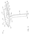
- Figure 3 is a perspective view of an exemplary cast-in plenum 100.
- Figure 4 is a side perspective view of an exemplary gas turbine rotor blade 50 that includes cast-in plenum 100.
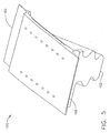
- Figure 5 is a top perspective view of gas turbine rotor blade 50 including cast-in plenum 100.
- Figure 6 is a bottom perspective view of gas turbine rotor blade 50 including cast-in plenum 100.
- platform 62 includes an outer surface 102 and an inner surface 104 that defines cast-in plenum 100. More specifically, following casting and coring of turbine rotor blade 50, inner surface 104 defines a substantially U-shaped cast-in plenum 100 entirely within outer surface 102. Accordingly, in the exemplary embodiment, cast-in plenum 100 is formed unitarily with and completely enclosed within platform 62.
- Cast-in plenum 100 includes a first plenum portion 106, a second plenum portion 108, and a third plenum portion 110 coupled in flow communication with plenums 106 and 108.
- First plenum portion 106 includes an upper surface 120, a lower surface 122, a first side 124, and a second side 126 that are each defined by inner surface 104.
- first side 124 has a generally concave shape that substantially mirrors a contour of second sidewall 72.
- Second plenum portion 108 includes an upper surface 130, a lower surface 132, a first side 134, and a second side 136 each defined by inner surface 104.
- first side 134 has a generally convex shape that substantially mirrors a contour of first sidewall 70.
- platform 62 includes a substantially solid portion 140 that extends between first plenum portion 106, second plenum portion 108, and third plenum portion 110 such that portion 140 is bounded by first plenum portion 106, second plenum portion 108, and third plenum portion 110.
- turbine rotor blade 50 is cored between first plenum portion 106, second plenum portion 108, and third plenum portion 110 such that a substantially solid base 140 is defined between airfoil 60, platform 62, and shank 64. Accordingly, fabricating rotor blade 50 such that cast-in plenum 100 is contained entirely within platform 62 facilitates increasing a structural integrity of turbine rotor blade 50.
- Turbine rotor blade 50 also includes a channel 150 that extends from a lower surface 152 of dovetail 66 to cast-in plenum 100. More specifically, channel 150 includes an opening 154 that extends through shank 64 such that lower surface 152 is coupled in flow communication with cast-in plenum 100. Channel 150 includes a first end 156 and a second end 158. Second end 158 is coupled in flow communication to third plenum portion 110.
- Turbine rotor blade 50 also include a plurality of openings 160 formed in flow communication with cast-in plenum 100 and extending between cast-in plenum 100 and platform outer surface 102. Openings 160 facilitate cooling platform 62.
- openings 160 extend between cast-in plenum 100 and platform outer surface 102.
- openings 160 extend between cast-in plenum 100 and a side 162 of platform outer surface 102.
- openings 160 extend between cast-in plenum 100 and a lower portion 164 of platform outer surface 102.
- openings 160 are sized to enable a predetermined amount of cooling airflow to be discharged therethrough to facilitate cooling platform 62.
- a core (not shown) is cast into turbine blade 50.
- the core is fabricated by injecting a liquid ceramic and graphite slurry into a core die (not shown). The slurry is heated to form a solid ceramic plenum core.
- the core is suspended in an turbine blade die (not shown) and hot wax is injected into the turbine blade die to surround the ceramic core. The hot wax solidifies and forms a turbine blade with the ceramic core suspended in the blade platform.
- the wax turbine blade with the ceramic core is then dipped in a ceramic slurry and allowed to dry. This procedure is repeated several times such that a shell is formed over the wax turbine blade.
- the wax is then melted out of the shell leaving a mold with a core suspended inside, and into which molten metal is poured. After the metal has solidified the shell is broken away and the core removed.
- cooling air entering channel first end 156 is channeled through channel 150 and discharged into cast-in plenum 100.
- the cooling air is then channeled from cast-in plenum 100 through openings 160 and around platform outer surface 102 to facilitate reducing an operating temperature of platform 62.
- the cooling air discharged from openings 160 facilitates reducing thermal strains induced to platform 62.
- Openings 160 are selectively positioned around an outer periphery 170 of platform 62 to facilitate compressor cooling air being channeled towards selected areas of platform 62 to facilitate optimizing the cooling of platform 62. Accordingly, when rotor blades 50 are coupled within the rotor assembly, channel 150 enables compressor discharge air to flow into cast-in plenum 100 and through openings 160 to facilitate reducing an operating temperature of platform 62.
- Figure 7 is a perspective view of an exemplary cast-in plenum 200.
- cast-in plenum 200 is formed unitarily with and completely enclosed within platform 62.
- Cast-in plenum 200 includes a first plenum portion 206, a second plenum portion 208.
- First plenum portion 206 includes an upper surface 220, a lower surface 222, a first side 224, and a second side 226 that are each defined by inner surface 204.
- first side 224 has a generally concave shape that substantially mirrors a contour of second sidewall 72.
- Second plenum portion 208 includes an upper surface 230, a lower surface 232, a first side 234, and a second side 236 each defined by inner surface 204.
- first side 234 has a generally convex shape that substantially mirrors a contour of first sidewall 70.
- Turbine rotor blade 50 also includes a first channel 250 that extends from a lower surface 252 of dovetail 66 to first plenum portion 206 and a second channel 251 that extends from lower surface 252 of dovetail 66 to second plenum portion 208.
- first and second channels 250, 251 are formed unitarily.
- first and second channels 250, 251 are formed as separate components such that first channel 250 channels cooling air to first plenum portion 206 and second channel 251 channels cooling air to second plenum portion 208.
- first and second channels 250, 251 are positioned along at least one of upstream side or skirt 90 and downstream side or skirt 92.
- channel 250 includes an opening 254 that extends through shank 64 such that lower surface 252 is coupled in flow communication with first plenum portion 206 and channel 251 includes an opening 255 that extends through shank 64 such that lower surface 252 is coupled in flow communication with second plenum portion 208.
- cooling air entering a first channel 250 and second channel 251 are channeled through channels 250 and 251 respectively and discharged into first plenum portion 206 and second plenum portion 208 respectively.
- the cooling air is then channeled from each respective plenum portion through openings 260 and around platform outer surface 102 to facilitate reducing an operating temperature of platform 62.
- the cooling air discharged from openings 260 facilitates reducing thermal strains induced to platform 62.
- Openings 260 are selectively positioned around an outer periphery 170 of platform 62 to facilitate compressor cooling air being channeled towards selected areas of platform 62 to facilitate optimizing the cooling of platform 62. Accordingly, when rotor blades 50 are coupled within the rotor assembly, channels 250 and 251 enable compressor discharge air to flow into cast-in plenums 206 and 208 and through openings 260 to facilitate reducing an operating temperature of platform 62.
- Figure 8 is a perspective view of an exemplary cast-in plenum 300.
- cast-in plenum 300 is formed unitarily with and completely enclosed within platform 62.
- Cast-in plenum 300 includes a first plenum portion 306 and a second plenum portion 308.
- First plenum portion 306 includes an upper surface 320, a lower surface 322, a first side 324, and a second side 326 that are each defined by inner surface 304.
- first side 324 has a generally concave shape that substantially mirrors a contour of second sidewall 72.
- Second plenum portion 308 includes an upper surface 330, a lower surface 332, a first side 334, and a second side 336 each defined by inner surface 304.
- first side 334 has a generally convex shape that substantially mirrors a contour of first sidewall 70.
- Turbine rotor blade 50 also includes a first channel 350 that extends from a lower surface 352 of dovetail 66 to first plenum portion 306 and a second channel 351 that extends from lower surface 352 of dovetail 66 to second plenum portion 308.
- first and second channels 350, 351 are formed as separate components such that first channel 350 channels cooling air to first plenum portion 306 and second channel 351 channels cooling air to second plenum portion 308.
- first channel 350 is positioned along at least one of upstream side or skirt 90 and downstream side or skirt 92
- second channel 351 is positioned along at least one of upstream side or skirt 90 and downstream side or skirt 92 opposite first channel 350.
- channel 350 includes an opening 354 that extends through shank 64 such that lower surface 352 is coupled in flow communication with first plenum portion 306, and second channel 351 includes an opening 355 that extends through shank 64 such that lower surface 352 is coupled in flow communication with second plenum portion 308.
- cooling air entering a first channel 350 and second channel 351 are channeled through channels 350 and 351 respectively and discharged into first plenum portion 306 and second plenum portion 308 respectively.
- the cooling air is then channeled from each respective plenum portion through openings 360 and around platform outer surface 302 to facilitate reducing an operating temperature of platform 62.
- the cooling air discharged from openings 360 facilitates reducing thermal strains induced to platform 62.
- Openings 360 are selectively positioned around an outer periphery 170 of platform 62 to facilitate compressor cooling air being channeled towards selected areas of platform 62 to facilitate optimizing the cooling of platform 62. Accordingly, when rotor blades 50 are coupled within the rotor assembly, channels 350 and 351 enable compressor discharge air to flow into cast-in plenums 306 and 308 and through openings 360 to facilitate reducing an operating temperature of platform 62.
- the above-described rotor blades provide a cost-effective and reliable method for supplying cooling air to facilitate reducing an operating temperature of the rotor blade platform. More specifically, through cooling flow, thermal stresses induced within the platform, and the operating temperature of the platform is facilitated to be reduced. Accordingly, platform oxidation, platform cracking, and platform creep deflection is also facilitated to be reduced. As a result, the rotor blade cooling cast-in plenums facilitate extending a useful life of the rotor blades and improving the operating efficiency of the gas turbine engine in a cost-effective and reliable manner.
- the method and apparatus described herein facilitate stabilizing platform hole cooling flow levels because the air is provided directly to the cast-in plenum via a dedicated channel, rather than relying on secondary airflows and/or leakages to facilitate cooling platform 62. Accordingly, the method and apparatus described herein facilitates eliminating the need for fabricating shank holes in the rotor blade.
- each rotor blade cooling circuit component can also be used in combination with other rotor blades, and is not limited to practice with only rotor blade 50 as described herein. Rather, the present invention can be implemented and utilized in connection with many other blade and cooling circuit configurations. For example, the methods and apparatus can be equally applied to rotor vanes such as, but not limited to an HPT vanes.
Landscapes
- Engineering & Computer Science (AREA)
- Mechanical Engineering (AREA)
- General Engineering & Computer Science (AREA)
- Turbine Rotor Nozzle Sealing (AREA)
- Molds, Cores, And Manufacturing Methods Thereof (AREA)
Claims (8)
- Aube de rotor de turbine (50) comprenant :une queue d'aronde (66) ;une plate-forme (62) couplée à ladite queue d'aronde, ladite plate-forme comprenant un collecteur intégré par moulage (100) formé à l'intérieur de ladite plate-forme ;une ailette (60) couplée à ladite plate-forme ; caractérisée en ce que ledit collecteur intégré par moulage comprenant au moins un canal dédié (150) s'étendant à partir d'une entrée (154) positionnée sur une surface inférieure en queue d'aronde (152) afin d'assurer le couplage d'une source de refroidissement en communication fluidique avec ledit collecteur intégré par moulage.
- Aube de rotor de turbine (50) selon la revendication 1, dans laquelle ledit collecteur intégré par moulage (100) comprend une première partie de collecteur (106), une deuxième partie de collecteur (108) et une troisième partie de collecteur (110) couplée en communication fluidique avec lesdites première et deuxième parties de collecteur.
- Aube de rotor de turbine (50) selon la revendication 1, comprenant, en outre, une première partie de collecteur (206), une deuxième partie de collecteur (208), un premier canal (250) qui s'étend entre une surface inférieure en queue d'aronde (252) et ladite première partie de collecteur intégré par moulage, et un second canal (201) qui s'étend entre la surface inférieure en queue d'aronde et ladite seconde partie de collecteur intégré par moulage.
- Aube de rotor de turbine (50) selon la revendication 2, dans laquelle lesdits premier et second canaux s'étendent le long d'au moins un côté amont de plate-forme (90) et d'un côté aval de plate-forme (92).
- Aube de rotor de turbine (50) selon la revendication 4, dans laquelle ledit premier canal s'étend le long d'au moins un côté amont de plate-forme (90) et d'un côté aval de plate-forme (92), ledit second canal s'étend le long d'au moins l'un dudit côté amont de plate-forme et dudit côté aval de plate-forme à l'opposé dudit premier canal.
- Aube de rotor de turbine (50) selon la revendication 1, dans laquelle ledit collecteur intégré par moulage (100) comprenant, en outre une première partie de collecteur (106) comprenant un premier côté (124) qui comporte un profil sensiblement concave, une deuxième partie de collecteur (108) comprenant un premier côté (134) qui comporte un profil sensiblement convexe, et une pluralité d'ouvertures (160) s'étendant entre ledit collecteur intégré par moulage et une surface externe de plate-forme (102), ladite pluralité d'ouvertures dimensionnées afin de faciliter la canalisation d'une quantité prédéterminée d'air de refroidissement vers ladite surface externe de plate-forme.
- Aube de rotor de turbine (50) selon la revendication 1, dans laquelle ladite plate-forme (62) comprend une partie sensiblement pleine (140) et un collecteur intégré par moulage, sensiblement en forme de U (100) s'étendant autour de ladite partie pleine, dans laquelle ladite partie pleine facilite l'augmentation de l'intégrité structurelle de ladite aube de rotor de turbine.
- Ensemble formant rotor de turbomoteur à gaz comprenant :un rotor (11) ; etune pluralité d'aubes de rotor (50) selon l'une quelconque des revendications précédentes, espacées circonférentiellement et couplées audit rotor.
Applications Claiming Priority (1)
| Application Number | Priority Date | Filing Date | Title |
|---|---|---|---|
| US10/903,414 US7144215B2 (en) | 2004-07-30 | 2004-07-30 | Method and apparatus for cooling gas turbine engine rotor blades |
Publications (2)
| Publication Number | Publication Date |
|---|---|
| EP1621725A1 EP1621725A1 (fr) | 2006-02-01 |
| EP1621725B1 true EP1621725B1 (fr) | 2008-05-28 |
Family
ID=34941822
Family Applications (1)
| Application Number | Title | Priority Date | Filing Date |
|---|---|---|---|
| EP05254269A Ceased EP1621725B1 (fr) | 2004-07-30 | 2005-07-07 | Aube de rotor de turbine et rotor de moteur à turbine à gaz comportant de telles aubes |
Country Status (4)
| Country | Link |
|---|---|
| US (1) | US7144215B2 (fr) |
| EP (1) | EP1621725B1 (fr) |
| JP (1) | JP4731237B2 (fr) |
| DE (1) | DE602005007115D1 (fr) |
Families Citing this family (20)
| Publication number | Priority date | Publication date | Assignee | Title |
|---|---|---|---|---|
| WO2009121716A1 (fr) * | 2008-03-31 | 2009-10-08 | Alstom Technology Ltd | Aube pour turbine à gaz |
| EP2243574A1 (fr) * | 2009-04-20 | 2010-10-27 | Siemens Aktiengesellschaft | Dispositif de coulée destiné à la fabrication d'une aube directrice de turbine d'une turbine à gaz et aube directrice de turbine |
| US9630277B2 (en) * | 2010-03-15 | 2017-04-25 | Siemens Energy, Inc. | Airfoil having built-up surface with embedded cooling passage |
| US8647064B2 (en) | 2010-08-09 | 2014-02-11 | General Electric Company | Bucket assembly cooling apparatus and method for forming the bucket assembly |
| US9416666B2 (en) | 2010-09-09 | 2016-08-16 | General Electric Company | Turbine blade platform cooling systems |
| US8636470B2 (en) | 2010-10-13 | 2014-01-28 | Honeywell International Inc. | Turbine blades and turbine rotor assemblies |
| GB2486488A (en) | 2010-12-17 | 2012-06-20 | Ge Aviat Systems Ltd | Testing a transient voltage protection device |
| US8628300B2 (en) | 2010-12-30 | 2014-01-14 | General Electric Company | Apparatus and methods for cooling platform regions of turbine rotor blades |
| US8840370B2 (en) | 2011-11-04 | 2014-09-23 | General Electric Company | Bucket assembly for turbine system |
| US8858160B2 (en) | 2011-11-04 | 2014-10-14 | General Electric Company | Bucket assembly for turbine system |
| US8870525B2 (en) | 2011-11-04 | 2014-10-28 | General Electric Company | Bucket assembly for turbine system |
| US8845289B2 (en) | 2011-11-04 | 2014-09-30 | General Electric Company | Bucket assembly for turbine system |
| US9022735B2 (en) | 2011-11-08 | 2015-05-05 | General Electric Company | Turbomachine component and method of connecting cooling circuits of a turbomachine component |
| US9039382B2 (en) | 2011-11-29 | 2015-05-26 | General Electric Company | Blade skirt |
| BR112014031269A2 (pt) | 2012-06-15 | 2017-08-08 | Gen Electric | aparelho de aerofólio de turbina e método de formação de um padrão de orifício de resfriamento. |
| US10041374B2 (en) * | 2014-04-04 | 2018-08-07 | United Technologies Corporation | Gas turbine engine component with platform cooling circuit |
| FR3065661B1 (fr) * | 2017-04-28 | 2019-06-14 | Safran Aircraft Engines | Noyau pour la fabrication par moulage a la cire perdue d'une aube de turbomachine |
| US20190323361A1 (en) * | 2018-04-20 | 2019-10-24 | United Technologies Corporation | Blade with inlet orifice on forward face of root |
| US11021966B2 (en) * | 2019-04-24 | 2021-06-01 | Raytheon Technologies Corporation | Vane core assemblies and methods |
| US11401819B2 (en) | 2020-12-17 | 2022-08-02 | Solar Turbines Incorporated | Turbine blade platform cooling holes |
Family Cites Families (35)
| Publication number | Priority date | Publication date | Assignee | Title |
|---|---|---|---|---|
| GB860126A (en) * | 1956-06-20 | 1961-02-01 | Wiggin & Co Ltd Henry | Improvements relating to the production of hollow metal articles |
| US3066910A (en) | 1958-07-09 | 1962-12-04 | Thompson Ramo Wooldridge Inc | Cooled turbine blade |
| US4312625A (en) | 1969-06-11 | 1982-01-26 | The United States Of America As Represented By The Secretary Of The Air Force | Hydrogen cooled turbine |
| CH580750A5 (fr) * | 1974-07-17 | 1976-10-15 | Bbc Sulzer Turbomaschinen | |
| US4156582A (en) * | 1976-12-13 | 1979-05-29 | General Electric Company | Liquid cooled gas turbine buckets |
| US4183456A (en) * | 1977-04-06 | 1980-01-15 | General Electric Company | Method of fabricating liquid cooled gas turbine components |
| US4244676A (en) * | 1979-06-01 | 1981-01-13 | General Electric Company | Cooling system for a gas turbine using a cylindrical insert having V-shaped notch weirs |
| GB2165315B (en) | 1984-10-04 | 1987-12-31 | Rolls Royce | Improvements in or relating to hollow fluid cooled turbine blades |
| GB2228540B (en) | 1988-12-07 | 1993-03-31 | Rolls Royce Plc | Cooling of turbine blades |
| US5122033A (en) * | 1990-11-16 | 1992-06-16 | Paul Marius A | Turbine blade unit |
| US5813835A (en) | 1991-08-19 | 1998-09-29 | The United States Of America As Represented By The Secretary Of The Air Force | Air-cooled turbine blade |
| US5382135A (en) | 1992-11-24 | 1995-01-17 | United Technologies Corporation | Rotor blade with cooled integral platform |
| JPH07119405A (ja) * | 1993-10-26 | 1995-05-09 | Hitachi Ltd | ガスタービン冷却翼 |
| DE69505407T2 (de) | 1994-08-24 | 1999-05-27 | Westinghouse Electric Corp., Pittsburgh, Pa. | Gasturbinenschaufel mit gekühlter plattform |
| KR100364183B1 (ko) | 1994-10-31 | 2003-02-19 | 웨스팅하우스 일렉트릭 코포레이션 | 냉각된플랫폼을구비한가스터빈블레이드 |
| JP3110275B2 (ja) | 1995-03-15 | 2000-11-20 | 三菱重工業株式会社 | ガスタービン動翼のプラットフォーム冷却装置 |
| JP2851578B2 (ja) * | 1996-03-12 | 1999-01-27 | 三菱重工業株式会社 | ガスタービン翼 |
| US5848876A (en) | 1997-02-11 | 1998-12-15 | Mitsubishi Heavy Industries, Ltd. | Cooling system for cooling platform of gas turbine moving blade |
| JP3457831B2 (ja) | 1997-03-17 | 2003-10-20 | 三菱重工業株式会社 | ガスタービン動翼の冷却プラットフォーム |
| CA2262064C (fr) | 1998-02-23 | 2002-09-03 | Mitsubishi Heavy Industries, Ltd. | Plate-forme d'aubes mobiles de turbine a gaz |
| JP3546135B2 (ja) * | 1998-02-23 | 2004-07-21 | 三菱重工業株式会社 | ガスタービン動翼のプラットフォーム |
| JPH11241602A (ja) | 1998-02-26 | 1999-09-07 | Toshiba Corp | ガスタービン翼 |
| US6092991A (en) | 1998-03-05 | 2000-07-25 | Mitsubishi Heavy Industries, Ltd. | Gas turbine blade |
| CA2231988C (fr) | 1998-03-12 | 2002-05-28 | Mitsubishi Heavy Industries, Ltd. | Pale de turbine a gaz |
| US6210111B1 (en) | 1998-12-21 | 2001-04-03 | United Technologies Corporation | Turbine blade with platform cooling |
| DE19926949B4 (de) | 1999-06-14 | 2011-01-05 | Alstom | Kühlungsanordnung für Schaufeln einer Gasturbine |
| US6254345B1 (en) | 1999-09-07 | 2001-07-03 | General Electric Company | Internally cooled blade tip shroud |
| US6402471B1 (en) | 2000-11-03 | 2002-06-11 | General Electric Company | Turbine blade for gas turbine engine and method of cooling same |
| US6416284B1 (en) | 2000-11-03 | 2002-07-09 | General Electric Company | Turbine blade for gas turbine engine and method of cooling same |
| DE50009497D1 (de) | 2000-11-16 | 2005-03-17 | Siemens Ag | Filmkühlung von Gasturbinenschaufeln mittels Schlitzen für Kühlluft |
| DE10059997B4 (de) | 2000-12-02 | 2014-09-11 | Alstom Technology Ltd. | Kühlbare Schaufel für eine Gasturbinenkomponente |
| DE10064265A1 (de) | 2000-12-22 | 2002-07-04 | Alstom Switzerland Ltd | Vorrichtung und Verfahren zur Kühlung einer Plattform einer Turbinenschaufel |
| EP1247939A1 (fr) | 2001-04-06 | 2002-10-09 | Siemens Aktiengesellschaft | Aube de turbine et son procédé de production |
| US6508620B2 (en) | 2001-05-17 | 2003-01-21 | Pratt & Whitney Canada Corp. | Inner platform impingement cooling by supply air from outside |
| US6945749B2 (en) * | 2003-09-12 | 2005-09-20 | Siemens Westinghouse Power Corporation | Turbine blade platform cooling system |
-
2004
- 2004-07-30 US US10/903,414 patent/US7144215B2/en not_active Expired - Lifetime
-
2005
- 2005-07-07 DE DE602005007115T patent/DE602005007115D1/de not_active Expired - Lifetime
- 2005-07-07 EP EP05254269A patent/EP1621725B1/fr not_active Ceased
- 2005-07-29 JP JP2005219799A patent/JP4731237B2/ja not_active Expired - Fee Related
Also Published As
| Publication number | Publication date |
|---|---|
| DE602005007115D1 (de) | 2008-07-10 |
| US20060024163A1 (en) | 2006-02-02 |
| US7144215B2 (en) | 2006-12-05 |
| JP2006046338A (ja) | 2006-02-16 |
| JP4731237B2 (ja) | 2011-07-20 |
| EP1621725A1 (fr) | 2006-02-01 |
Similar Documents
| Publication | Publication Date | Title |
|---|---|---|
| EP1621727B1 (fr) | Aube de rotor de turbine et rotor de moteur à turbine à gaz comportant de telles aubes | |
| US7131817B2 (en) | Method and apparatus for cooling gas turbine engine rotor blades | |
| EP1621725B1 (fr) | Aube de rotor de turbine et rotor de moteur à turbine à gaz comportant de telles aubes | |
| US6915840B2 (en) | Methods and apparatus for fabricating turbine engine airfoils | |
| US7976281B2 (en) | Turbine rotor blade and method of assembling the same | |
| US6062817A (en) | Apparatus and methods for cooling slot step elimination | |
| US6132169A (en) | Turbine airfoil and methods for airfoil cooling | |
| US7513738B2 (en) | Methods and apparatus for cooling gas turbine rotor blades | |
| US6485262B1 (en) | Methods and apparatus for extending gas turbine engine airfoils useful life | |
| US6932570B2 (en) | Methods and apparatus for extending gas turbine engine airfoils useful life | |
| EP1106280B1 (fr) | Noyau pour contrôler l'épaisseur d'une aube d'une turbine et méthode | |
| JP2003214108A (ja) | 改善された温度特性を有する後縁を備えた高圧タービンのための動翼 | |
| US7387492B2 (en) | Methods and apparatus for cooling turbine blade trailing edges | |
| JP2003193804A (ja) | 高圧タービンブレードの後縁の高温状態の改良 | |
| KR102764478B1 (ko) | 내부 교차 통로 및 핀 어레이를 갖는 에어포일 | |
| JP2016540150A (ja) | ガスタービンエンジンのベーンセグメント用のインベストメント鋳造法 | |
| US6957948B2 (en) | Turbine blade attachment lightening holes |
Legal Events
| Date | Code | Title | Description |
|---|---|---|---|
| PUAI | Public reference made under article 153(3) epc to a published international application that has entered the european phase |
Free format text: ORIGINAL CODE: 0009012 |
|
| AK | Designated contracting states |
Kind code of ref document: A1 Designated state(s): AT BE BG CH CY CZ DE DK EE ES FI FR GB GR HU IE IS IT LI LT LU LV MC NL PL PT RO SE SI SK TR |
|
| AX | Request for extension of the european patent |
Extension state: AL BA HR MK YU |
|
| 17P | Request for examination filed |
Effective date: 20060801 |
|
| AKX | Designation fees paid |
Designated state(s): DE GB GR |
|
| 17Q | First examination report despatched |
Effective date: 20060831 |
|
| GRAP | Despatch of communication of intention to grant a patent |
Free format text: ORIGINAL CODE: EPIDOSNIGR1 |
|
| RBV | Designated contracting states (corrected) |
Designated state(s): DE FR GB |
|
| GRAS | Grant fee paid |
Free format text: ORIGINAL CODE: EPIDOSNIGR3 |
|
| GRAA | (expected) grant |
Free format text: ORIGINAL CODE: 0009210 |
|
| AK | Designated contracting states |
Kind code of ref document: B1 Designated state(s): DE FR GB |
|
| REG | Reference to a national code |
Ref country code: GB Ref legal event code: FG4D |
|
| REF | Corresponds to: |
Ref document number: 602005007115 Country of ref document: DE Date of ref document: 20080710 Kind code of ref document: P |
|
| PLBE | No opposition filed within time limit |
Free format text: ORIGINAL CODE: 0009261 |
|
| STAA | Information on the status of an ep patent application or granted ep patent |
Free format text: STATUS: NO OPPOSITION FILED WITHIN TIME LIMIT |
|
| 26N | No opposition filed |
Effective date: 20090303 |
|
| REG | Reference to a national code |
Ref country code: FR Ref legal event code: PLFP Year of fee payment: 12 |
|
| REG | Reference to a national code |
Ref country code: FR Ref legal event code: PLFP Year of fee payment: 13 |
|
| PGFP | Annual fee paid to national office [announced via postgrant information from national office to epo] |
Ref country code: GB Payment date: 20170727 Year of fee payment: 13 Ref country code: DE Payment date: 20170727 Year of fee payment: 13 Ref country code: FR Payment date: 20170726 Year of fee payment: 13 |
|
| REG | Reference to a national code |
Ref country code: DE Ref legal event code: R119 Ref document number: 602005007115 Country of ref document: DE |
|
| GBPC | Gb: european patent ceased through non-payment of renewal fee |
Effective date: 20180707 |
|
| PG25 | Lapsed in a contracting state [announced via postgrant information from national office to epo] |
Ref country code: GB Free format text: LAPSE BECAUSE OF NON-PAYMENT OF DUE FEES Effective date: 20180707 Ref country code: FR Free format text: LAPSE BECAUSE OF NON-PAYMENT OF DUE FEES Effective date: 20180731 Ref country code: DE Free format text: LAPSE BECAUSE OF NON-PAYMENT OF DUE FEES Effective date: 20190201 |