EP1365119A2 - Plasmabrennstoffverfahren zur NOX Kontrolle von magerbetriebenen Brennkraftmaschinen - Google Patents
Plasmabrennstoffverfahren zur NOX Kontrolle von magerbetriebenen Brennkraftmaschinen Download PDFInfo
- Publication number
- EP1365119A2 EP1365119A2 EP03077728A EP03077728A EP1365119A2 EP 1365119 A2 EP1365119 A2 EP 1365119A2 EP 03077728 A EP03077728 A EP 03077728A EP 03077728 A EP03077728 A EP 03077728A EP 1365119 A2 EP1365119 A2 EP 1365119A2
- Authority
- EP
- European Patent Office
- Prior art keywords
- fuel
- gas
- catalyst
- reducing
- reactive
- Prior art date
- Legal status (The legal status is an assumption and is not a legal conclusion. Google has not performed a legal analysis and makes no representation as to the accuracy of the status listed.)
- Withdrawn
Links
Images


Classifications
-
- F—MECHANICAL ENGINEERING; LIGHTING; HEATING; WEAPONS; BLASTING
- F01—MACHINES OR ENGINES IN GENERAL; ENGINE PLANTS IN GENERAL; STEAM ENGINES
- F01N—GAS-FLOW SILENCERS OR EXHAUST APPARATUS FOR MACHINES OR ENGINES IN GENERAL; GAS-FLOW SILENCERS OR EXHAUST APPARATUS FOR INTERNAL-COMBUSTION ENGINES
- F01N3/00—Exhaust or silencing apparatus having means for purifying, rendering innocuous, or otherwise treating exhaust
- F01N3/08—Exhaust or silencing apparatus having means for purifying, rendering innocuous, or otherwise treating exhaust for rendering innocuous
- F01N3/10—Exhaust or silencing apparatus having means for purifying, rendering innocuous, or otherwise treating exhaust for rendering innocuous by thermal or catalytic conversion of noxious components of exhaust
- F01N3/18—Exhaust or silencing apparatus having means for purifying, rendering innocuous, or otherwise treating exhaust for rendering innocuous by thermal or catalytic conversion of noxious components of exhaust characterised by methods of operation; Control
- F01N3/20—Exhaust or silencing apparatus having means for purifying, rendering innocuous, or otherwise treating exhaust for rendering innocuous by thermal or catalytic conversion of noxious components of exhaust characterised by methods of operation; Control specially adapted for catalytic conversion
- F01N3/206—Adding periodically or continuously substances to exhaust gases for promoting purification, e.g. catalytic material in liquid form, NOx reducing agents
- F01N3/2066—Selective catalytic reduction [SCR]
-
- B—PERFORMING OPERATIONS; TRANSPORTING
- B01—PHYSICAL OR CHEMICAL PROCESSES OR APPARATUS IN GENERAL
- B01D—SEPARATION
- B01D53/00—Separation of gases or vapours; Recovering vapours of volatile solvents from gases; Chemical or biological purification of waste gases, e.g. engine exhaust gases, smoke, fumes, flue gases, aerosols
- B01D53/34—Chemical or biological purification of waste gases
- B01D53/92—Chemical or biological purification of waste gases of engine exhaust gases
- B01D53/94—Chemical or biological purification of waste gases of engine exhaust gases by catalytic processes
- B01D53/9404—Removing only nitrogen compounds
- B01D53/9409—Nitrogen oxides
- B01D53/9431—Processes characterised by a specific device
-
- B—PERFORMING OPERATIONS; TRANSPORTING
- B01—PHYSICAL OR CHEMICAL PROCESSES OR APPARATUS IN GENERAL
- B01D—SEPARATION
- B01D53/00—Separation of gases or vapours; Recovering vapours of volatile solvents from gases; Chemical or biological purification of waste gases, e.g. engine exhaust gases, smoke, fumes, flue gases, aerosols
- B01D53/34—Chemical or biological purification of waste gases
- B01D53/92—Chemical or biological purification of waste gases of engine exhaust gases
- B01D53/94—Chemical or biological purification of waste gases of engine exhaust gases by catalytic processes
- B01D53/9495—Controlling the catalytic process
-
- F—MECHANICAL ENGINEERING; LIGHTING; HEATING; WEAPONS; BLASTING
- F01—MACHINES OR ENGINES IN GENERAL; ENGINE PLANTS IN GENERAL; STEAM ENGINES
- F01N—GAS-FLOW SILENCERS OR EXHAUST APPARATUS FOR MACHINES OR ENGINES IN GENERAL; GAS-FLOW SILENCERS OR EXHAUST APPARATUS FOR INTERNAL-COMBUSTION ENGINES
- F01N13/00—Exhaust or silencing apparatus characterised by constructional features
- F01N13/009—Exhaust or silencing apparatus characterised by constructional features having two or more separate purifying devices arranged in series
-
- F—MECHANICAL ENGINEERING; LIGHTING; HEATING; WEAPONS; BLASTING
- F01—MACHINES OR ENGINES IN GENERAL; ENGINE PLANTS IN GENERAL; STEAM ENGINES
- F01N—GAS-FLOW SILENCERS OR EXHAUST APPARATUS FOR MACHINES OR ENGINES IN GENERAL; GAS-FLOW SILENCERS OR EXHAUST APPARATUS FOR INTERNAL-COMBUSTION ENGINES
- F01N13/00—Exhaust or silencing apparatus characterised by constructional features
- F01N13/009—Exhaust or silencing apparatus characterised by constructional features having two or more separate purifying devices arranged in series
- F01N13/0093—Exhaust or silencing apparatus characterised by constructional features having two or more separate purifying devices arranged in series the purifying devices are of the same type
-
- F—MECHANICAL ENGINEERING; LIGHTING; HEATING; WEAPONS; BLASTING
- F01—MACHINES OR ENGINES IN GENERAL; ENGINE PLANTS IN GENERAL; STEAM ENGINES
- F01N—GAS-FLOW SILENCERS OR EXHAUST APPARATUS FOR MACHINES OR ENGINES IN GENERAL; GAS-FLOW SILENCERS OR EXHAUST APPARATUS FOR INTERNAL-COMBUSTION ENGINES
- F01N3/00—Exhaust or silencing apparatus having means for purifying, rendering innocuous, or otherwise treating exhaust
- F01N3/08—Exhaust or silencing apparatus having means for purifying, rendering innocuous, or otherwise treating exhaust for rendering innocuous
- F01N3/0807—Exhaust or silencing apparatus having means for purifying, rendering innocuous, or otherwise treating exhaust for rendering innocuous by using absorbents or adsorbents
- F01N3/0814—Exhaust or silencing apparatus having means for purifying, rendering innocuous, or otherwise treating exhaust for rendering innocuous by using absorbents or adsorbents combined with catalytic converters, e.g. NOx absorption/storage reduction catalysts
-
- F—MECHANICAL ENGINEERING; LIGHTING; HEATING; WEAPONS; BLASTING
- F01—MACHINES OR ENGINES IN GENERAL; ENGINE PLANTS IN GENERAL; STEAM ENGINES
- F01N—GAS-FLOW SILENCERS OR EXHAUST APPARATUS FOR MACHINES OR ENGINES IN GENERAL; GAS-FLOW SILENCERS OR EXHAUST APPARATUS FOR INTERNAL-COMBUSTION ENGINES
- F01N3/00—Exhaust or silencing apparatus having means for purifying, rendering innocuous, or otherwise treating exhaust
- F01N3/08—Exhaust or silencing apparatus having means for purifying, rendering innocuous, or otherwise treating exhaust for rendering innocuous
- F01N3/0807—Exhaust or silencing apparatus having means for purifying, rendering innocuous, or otherwise treating exhaust for rendering innocuous by using absorbents or adsorbents
- F01N3/0828—Exhaust or silencing apparatus having means for purifying, rendering innocuous, or otherwise treating exhaust for rendering innocuous by using absorbents or adsorbents characterised by the absorbed or adsorbed substances
- F01N3/0842—Nitrogen oxides
-
- B—PERFORMING OPERATIONS; TRANSPORTING
- B01—PHYSICAL OR CHEMICAL PROCESSES OR APPARATUS IN GENERAL
- B01D—SEPARATION
- B01D2255/00—Catalysts
- B01D2255/10—Noble metals or compounds thereof
- B01D2255/102—Platinum group metals
- B01D2255/1021—Platinum
-
- B—PERFORMING OPERATIONS; TRANSPORTING
- B01—PHYSICAL OR CHEMICAL PROCESSES OR APPARATUS IN GENERAL
- B01D—SEPARATION
- B01D2255/00—Catalysts
- B01D2255/50—Zeolites
- B01D2255/504—ZSM 5 zeolites
-
- B—PERFORMING OPERATIONS; TRANSPORTING
- B01—PHYSICAL OR CHEMICAL PROCESSES OR APPARATUS IN GENERAL
- B01D—SEPARATION
- B01D2259/00—Type of treatment
- B01D2259/80—Employing electric, magnetic, electromagnetic or wave energy, or particle radiation
- B01D2259/818—Employing electrical discharges or the generation of a plasma
-
- F—MECHANICAL ENGINEERING; LIGHTING; HEATING; WEAPONS; BLASTING
- F01—MACHINES OR ENGINES IN GENERAL; ENGINE PLANTS IN GENERAL; STEAM ENGINES
- F01N—GAS-FLOW SILENCERS OR EXHAUST APPARATUS FOR MACHINES OR ENGINES IN GENERAL; GAS-FLOW SILENCERS OR EXHAUST APPARATUS FOR INTERNAL-COMBUSTION ENGINES
- F01N2240/00—Combination or association of two or more different exhaust treating devices, or of at least one such device with an auxiliary device, not covered by indexing codes F01N2230/00 or F01N2250/00, one of the devices being
- F01N2240/28—Combination or association of two or more different exhaust treating devices, or of at least one such device with an auxiliary device, not covered by indexing codes F01N2230/00 or F01N2250/00, one of the devices being a plasma reactor
-
- F—MECHANICAL ENGINEERING; LIGHTING; HEATING; WEAPONS; BLASTING
- F01—MACHINES OR ENGINES IN GENERAL; ENGINE PLANTS IN GENERAL; STEAM ENGINES
- F01N—GAS-FLOW SILENCERS OR EXHAUST APPARATUS FOR MACHINES OR ENGINES IN GENERAL; GAS-FLOW SILENCERS OR EXHAUST APPARATUS FOR INTERNAL-COMBUSTION ENGINES
- F01N2240/00—Combination or association of two or more different exhaust treating devices, or of at least one such device with an auxiliary device, not covered by indexing codes F01N2230/00 or F01N2250/00, one of the devices being
- F01N2240/30—Combination or association of two or more different exhaust treating devices, or of at least one such device with an auxiliary device, not covered by indexing codes F01N2230/00 or F01N2250/00, one of the devices being a fuel reformer
-
- F—MECHANICAL ENGINEERING; LIGHTING; HEATING; WEAPONS; BLASTING
- F01—MACHINES OR ENGINES IN GENERAL; ENGINE PLANTS IN GENERAL; STEAM ENGINES
- F01N—GAS-FLOW SILENCERS OR EXHAUST APPARATUS FOR MACHINES OR ENGINES IN GENERAL; GAS-FLOW SILENCERS OR EXHAUST APPARATUS FOR INTERNAL-COMBUSTION ENGINES
- F01N2570/00—Exhaust treating apparatus eliminating, absorbing or adsorbing specific elements or compounds
- F01N2570/14—Nitrogen oxides
-
- F—MECHANICAL ENGINEERING; LIGHTING; HEATING; WEAPONS; BLASTING
- F01—MACHINES OR ENGINES IN GENERAL; ENGINE PLANTS IN GENERAL; STEAM ENGINES
- F01N—GAS-FLOW SILENCERS OR EXHAUST APPARATUS FOR MACHINES OR ENGINES IN GENERAL; GAS-FLOW SILENCERS OR EXHAUST APPARATUS FOR INTERNAL-COMBUSTION ENGINES
- F01N2610/00—Adding substances to exhaust gases
- F01N2610/03—Adding substances to exhaust gases the substance being hydrocarbons, e.g. engine fuel
-
- F—MECHANICAL ENGINEERING; LIGHTING; HEATING; WEAPONS; BLASTING
- F01—MACHINES OR ENGINES IN GENERAL; ENGINE PLANTS IN GENERAL; STEAM ENGINES
- F01N—GAS-FLOW SILENCERS OR EXHAUST APPARATUS FOR MACHINES OR ENGINES IN GENERAL; GAS-FLOW SILENCERS OR EXHAUST APPARATUS FOR INTERNAL-COMBUSTION ENGINES
- F01N2610/00—Adding substances to exhaust gases
- F01N2610/06—Adding substances to exhaust gases the substance being in the gaseous form
-
- F—MECHANICAL ENGINEERING; LIGHTING; HEATING; WEAPONS; BLASTING
- F01—MACHINES OR ENGINES IN GENERAL; ENGINE PLANTS IN GENERAL; STEAM ENGINES
- F01N—GAS-FLOW SILENCERS OR EXHAUST APPARATUS FOR MACHINES OR ENGINES IN GENERAL; GAS-FLOW SILENCERS OR EXHAUST APPARATUS FOR INTERNAL-COMBUSTION ENGINES
- F01N2610/00—Adding substances to exhaust gases
- F01N2610/08—Adding substances to exhaust gases with prior mixing of the substances with a gas, e.g. air
-
- F—MECHANICAL ENGINEERING; LIGHTING; HEATING; WEAPONS; BLASTING
- F01—MACHINES OR ENGINES IN GENERAL; ENGINE PLANTS IN GENERAL; STEAM ENGINES
- F01N—GAS-FLOW SILENCERS OR EXHAUST APPARATUS FOR MACHINES OR ENGINES IN GENERAL; GAS-FLOW SILENCERS OR EXHAUST APPARATUS FOR INTERNAL-COMBUSTION ENGINES
- F01N3/00—Exhaust or silencing apparatus having means for purifying, rendering innocuous, or otherwise treating exhaust
- F01N3/08—Exhaust or silencing apparatus having means for purifying, rendering innocuous, or otherwise treating exhaust for rendering innocuous
- F01N3/0807—Exhaust or silencing apparatus having means for purifying, rendering innocuous, or otherwise treating exhaust for rendering innocuous by using absorbents or adsorbents
-
- F—MECHANICAL ENGINEERING; LIGHTING; HEATING; WEAPONS; BLASTING
- F02—COMBUSTION ENGINES; HOT-GAS OR COMBUSTION-PRODUCT ENGINE PLANTS
- F02M—SUPPLYING COMBUSTION ENGINES IN GENERAL WITH COMBUSTIBLE MIXTURES OR CONSTITUENTS THEREOF
- F02M26/00—Engine-pertinent apparatus for adding exhaust gases to combustion-air, main fuel or fuel-air mixture, e.g. by exhaust gas recirculation [EGR] systems
- F02M26/13—Arrangement or layout of EGR passages, e.g. in relation to specific engine parts or for incorporation of accessories
- F02M26/36—Arrangement or layout of EGR passages, e.g. in relation to specific engine parts or for incorporation of accessories with means for adding fluids other than exhaust gas to the recirculation passage; with reformers
-
- Y—GENERAL TAGGING OF NEW TECHNOLOGICAL DEVELOPMENTS; GENERAL TAGGING OF CROSS-SECTIONAL TECHNOLOGIES SPANNING OVER SEVERAL SECTIONS OF THE IPC; TECHNICAL SUBJECTS COVERED BY FORMER USPC CROSS-REFERENCE ART COLLECTIONS [XRACs] AND DIGESTS
- Y02—TECHNOLOGIES OR APPLICATIONS FOR MITIGATION OR ADAPTATION AGAINST CLIMATE CHANGE
- Y02A—TECHNOLOGIES FOR ADAPTATION TO CLIMATE CHANGE
- Y02A50/00—TECHNOLOGIES FOR ADAPTATION TO CLIMATE CHANGE in human health protection, e.g. against extreme weather
- Y02A50/20—Air quality improvement or preservation, e.g. vehicle emission control or emission reduction by using catalytic converters
-
- Y—GENERAL TAGGING OF NEW TECHNOLOGICAL DEVELOPMENTS; GENERAL TAGGING OF CROSS-SECTIONAL TECHNOLOGIES SPANNING OVER SEVERAL SECTIONS OF THE IPC; TECHNICAL SUBJECTS COVERED BY FORMER USPC CROSS-REFERENCE ART COLLECTIONS [XRACs] AND DIGESTS
- Y02—TECHNOLOGIES OR APPLICATIONS FOR MITIGATION OR ADAPTATION AGAINST CLIMATE CHANGE
- Y02C—CAPTURE, STORAGE, SEQUESTRATION OR DISPOSAL OF GREENHOUSE GASES [GHG]
- Y02C20/00—Capture or disposal of greenhouse gases
- Y02C20/10—Capture or disposal of greenhouse gases of nitrous oxide (N2O)
-
- Y—GENERAL TAGGING OF NEW TECHNOLOGICAL DEVELOPMENTS; GENERAL TAGGING OF CROSS-SECTIONAL TECHNOLOGIES SPANNING OVER SEVERAL SECTIONS OF THE IPC; TECHNICAL SUBJECTS COVERED BY FORMER USPC CROSS-REFERENCE ART COLLECTIONS [XRACs] AND DIGESTS
- Y02—TECHNOLOGIES OR APPLICATIONS FOR MITIGATION OR ADAPTATION AGAINST CLIMATE CHANGE
- Y02T—CLIMATE CHANGE MITIGATION TECHNOLOGIES RELATED TO TRANSPORTATION
- Y02T10/00—Road transport of goods or passengers
- Y02T10/10—Internal combustion engine [ICE] based vehicles
- Y02T10/12—Improving ICE efficiencies
Definitions
- This invention relates generally to a system (method and apparatus) for removing emissions from the exhaust gases of a vehicle's internal combustion engine and more particularly to the reduction of nitrogen oxides to free nitrogen.
- the invention is particularly applicable to and will be described with specific reference to a system for the removal of nitrogen oxides from diesel engines operating at lean air/fuel ratios which promote the formation of NO x .
- a system for the removal of nitrogen oxides from diesel engines operating at lean air/fuel ratios which promote the formation of NO x are particularly applicable.
- the invention has broader application and could be applied, for example, to gasoline engines operated at lean burn conditions, or any engine exhaust stream containing oxygen.
- This invention is directed to the removal of nitrogen oxides, NO x , from the exhaust gases of internal combustion engines, particularly diesel engines, which operate at combustion conditions with air in excess of that required for stoichiometric combustion, i.e., lean. It is well known that fuel efficiency improvements in excess of 10% can be achieved in gasoline engines operated at "lean burn” conditions when compared to today's engines which cycle the air to fuel ratio about stoichiometric. Diesel engines, by their nature, operate at lean conditions and have always achieved high fuel efficiencies.
- a catalytic reduction method essentially comprises passing the exhaust gas over a catalyst bed in the presence of a reducing gas to convert NO x into nitrogen.
- Two types of catalytic reduction are practiced. The first type is non-selective catalyst reduction and the second type is selective catalyst reduction (SCR). This invention relates to SCR systems.
- a reducing agent or reductant is supplied to the exhaust stream and the mixture is then contacted with a catalyst.
- Typical reducing agents used in industrial processes for removal of NO x from waste streams, such as urea or ammonia, are not suited for vehicular applications because of the large quantities of the reducing agent required. Any SCR method using a separate reducing agent is simply not practical for vehicle applications. Additional storage tanks have to be provided. Also, measures have to be taken to account for the environmental affects on the reducing agent such as freezing. In addition, space limitations for the reactor have to be addressed.
- the NO x plasma art has also utilized a reducing agent with the plasma.
- diesel fuel is injected upstream of a NO x plasma reactor to produce. N 2 .
- diesel fuel is injected into the exhaust gas prior to entering a two stage microwave converter.
- diesel fuel is passed through a plasma prior to mixing with the exhaust gas and the entire mixture is passed through a second plasma reactor. See also European patent application 0 366 876 B1 published May 12, 1993, and the '876 patent for injecting other reducing agents, i.e., ammonia, into the exhaust gas passing through the plasma.
- plasma has been generated in air to react with or oxidize coke inherently produced by diesel engines.
- the '677 and the '876 patents illustrate plasma reactors burning soot with air introduced in a metallic bed situated in a plasma field, i.e., thermal plasma or a ferro-electric bed in the plasma, i.e., non-thermal plasma.
- a system for converting noxious emissions in the exhaust stream produced by an internal combustion engine operating at lean air/fuel ratios into benign emissions
- a system for converting noxious emissions in the exhaust stream produced by an internal combustion engine operating at lean air/fuel ratios into benign emissions
- the highly reactive mixture is introduced into the exhaust stream upstream of a reducing catalyst whereby a small quantity of fuel produced with little energy expenditure effectively disposes of oxides of nitrogen resulting from lean burn engine conditions.
- the reactive mixture is characterized as substantially comprising (i.e., more than 50%) one or more HC reductants selected from the group consisting of i) normal, unbranched aliphatics having a chain length where the number of carbon atoms per organic molecule is equal to or greater than 7, ii) olefins and iii) oxygenates.
- HC reductants selected from the group consisting of i) normal, unbranched aliphatics having a chain length where the number of carbon atoms per organic molecule is equal to or greater than 7, ii) olefins and iii) oxygenates.
- Branched aliphatic and aromatic organic molecules typically present in significant quantities when diesel fuel or fuel oil is injected into the exhaust stream are minimized.
- a specific species of the reactive mixture can be generated having a significant quantity (which may be less than 50%) of short chain HC, such as oxygenated organic molecules whereby the reactive mixture is able to permeate conventional catalyst beds having microporous crystallite structures such as catalysts containing zeolites to significantly increase the contact area of the catalyst and improve the efficiency of the catalyst to reduce oxides of nitrogen to free nitrogen.
- the low weight or short chain oxygenated organic molecules having few carbon atoms (i.e. 3) would include at least one oxygen atom for every three carbon atoms to produce reactive reducing compounds.
- the highly reactive mixture such as a conventional cracking unit producing short chain HC molecules which are further reacted with oxygen over an oxidation catalyst to produce the reactive mixture.
- an especially important feature of the invention is the utilization of a non-thermal plasma reactor which is particularly suited to generate the highly reactive mixture in the presence of oxygen in an effective and an energy efficient manner.
- the efficiencies of the plasma reactor for generating a reducing gas and its suitability for use in the harsh environment which the vehicle is exposed to provide a stand alone inventive feature even if the plasma reactor was operated to simply produce a reducing agent which would parallel the reactivity of conventional reducing agents generated from the engine fuel and not the highly reactive reducing mixture discussed above.
- the fuel is diesel fuel and a carrier gas having some oxygen content is admitted with the fuel into the non-thermal plasma reactor chamber.
- the oxygen has a high probability for disassociation within the plasma with the result that oxygen atoms are simultaneously incorporated into organic molecules produced by the dissociation of the fuel oil caused in good part by the plasma.
- the organic molecules thus produced are to a significant extent short chain, unbranched, reactive organic molecules which are generated in a most energy efficient manner.
- the non-thermal plasma reactor chamber includes spaced electrodes and a bed of dielectric particles between the spaced electrodes so that the reaction chamber is a dielectric barrier plasma reaction chamber with the plasma generated by an AC potential thus avoiding arc discharge occurrences otherwise requiring sophisticated electronic circuits sensing and controlling voltage pulsing to the reaction chamber.
- the carrier gas is either a portion of the exhaust gas (i.e., EGR) or air whereby coking within the pellet bed is avoided by the presence of oxygen in the carrier gas which can react with any free carbon over a large effective surface area resulting from the dielectric bed.
- EGR exhaust gas
- the dielectric particles in the bed not only cause a uniform plasma throughout the bed but may be optionally coated with oxidation catalysts to speed the desired reactions.
- the plasma reactor can simply receive the oxygen and fuel oil to produce the reactive material as stated above or optionally, a partial oxidation catalyst may be provided upstream of the plasma reactor to trim the reactive mixture to a desired composition or optionally a thermal cracking unit can be provided downstream of the plasma reactor such that a small sized plasma reactor with oxygen will further reduce the diesel fuel while forming the reactive gas material whereby a number of different systems with specific attributes can be configured utilizing the benefits obtained in a reducing gas produced by free radical oxidation reactions caused by the plasma reactor.
- An important general object of the invention is to provide a plasma reactor through which fuel and a carrier gas are passed to produce a reducing agent for an SCR catalyst system.
- Yet another more specific object of the invention is the provision of a plasma reactor for cracking of diesel fuel in a plasma reactor which avoids coke.
- Another specific but important object of the invention is a system (method and apparatus) which utilizes a plasma reactor to produce from diesel fuel a highly reactive reducing gas characterized by a short chain molecular structure able to permeate a catalyst bed to achieve high NO x reduction efficiencies thereby permitting less fuel to be used as a reducing gas when compared to other conventional arrangements using diesel fuel as a reducing gas in an SCR system.
- a more specific object of the invention is the provision of an SCR system for removing noxious emissions produced by lean burn engines which uses a plasma reactor to produce a reducing agent having desired reactive organic molecular structures by generating strong energetic plasmas on a minor portion of the engine's fuel without imposing excessive energy loads on the engine.
- a more subtle but important object of the invention is to generate a highly reactive reducing gas for internal combustion engines operating at lean burn conditions whereby downstream NO x catalysts can be developed or existing catalysts can be utilized without the deactivation or thermal degradation concerns which must currently be addressed.
- An important object of the invention is the utilization of a carrier gas with diesel fuel in a plasma reactor to produce a highly reactive reducing gas at lower temperatures than required for conventional thermal cracking of diesel fuel.
- a more subtle but important object of the invention is to provide, from the engine's fuel, a highly reactive reducing gas mixture for use in an SCR system which is able to maintain its reactivity notwithstanding the harsh vehicular environment, especially the cold temperature limits, which it is subjected to.
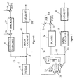
- FIG. 1 An internal combustion engine whether of the diesel or gasoline fuel type, is indicated by block 10.
- Engine 10 is operated lean or with a "lean-burn" engine fuel strategy.
- gasoline engines with lean-burn strategies indicate an overall fuel savings of 10% when compared to gasoline engines which use fuel control strategies which cycle the engine about stoichiometric.
- a "lean” engine as used herein and in the claims is an engine that operates at an A/F ratio such that the nitrogen oxide emissions cannot be continuously treated by conventional three way catalysts (TWC).
- TWCs are able to treat gasoline powered engines using fueling strategies that cycle lambda (A/F / A/F necessary to produce stoichiometric combustion) at lean conditions as high as 1.05.
- this invention introduces a reducing gas having a particular reactive mixture through a reactive mixture duct 12 into the exhaust gas stream in exhaust gas stream duct 13.
- the reactive mixture and the exhaust gas stream are passed over a deNO x reducing catalyst 15 whereby NO x is converted to free or elemental nitrogen, N 2 and the stream is then passed over a second oxidizing catalyst 16 for oxidizing any unconverted emissions such as HC and CO.
- the benign gaseous emissions are then exhausted to atmosphere.
- Reducing and oxidizing catalyst 15, 16 can be formed into one catalytic converter or be different coatings on the same monolithic block.
- the invention as described thus far is a conventional SCR system with the exception that the reactive mixture in duct 12 is highly reactive and ideally suited for reducing NO x and reducing catalyst 15.
- a reactive mixture somewhat similar to that produced in the preferred embodiment, can be produced by passing a liquid fuel from a fuel duct 17 mixed with air as a carrier gas from a carrier duct 18 through a cracking unit 19 which could be a zeolite catalyst at an elevated temperature to produce the desired short chain organic molecules as described in the Thermal Cracking article.
- a metered quantity of air at air duct 20 is then added to the cracked fuel and the mixture is passed over an oxidation catalyst 22 to provide formulation of desired aldehydes and ketones making up a portion of the reactive mixture in duct 12.
- Oxidation catalyst 22 as well as catalyst 16 is a base metal oxide such as an oxide of copper, cobalt, chromium, cerium, etc., or a noble metal catalyst containing palladium or platinum supported on Al 2 0 3 , Ti0 2 , CeO 2 etc.
- the reactive gas mixture of the invention may be best defined by reference to the graphs illustrated in Figure 7, 8, 9 and 10.
- Figures 7-10 show the ability of various classes of pure HCs which can be produced from fuel oil to reduce NO x .
- the NO x conversion percentage is plotted on the y-axis and the temperature of the exhaust gas at the inlet for the catalyst is plotted on the x-axis for each graph.
- the exhaust gases were passed over a Pt/Zeolite lean NO x catalyst (reducing catalyst 15) and all HC reductants were run at approximately the same C/N (carbon/nitrogen) ratio.
- the activity of the HC classes investigated is compared to the reducing activity of No. 2 diesel fuel injected into the exhaust stream at the catalyst inlet.
- the NO x conversion reactivity for No. 2 fuel oil for each graph is shown by the trace passing through triangles and designated by reference numeral 100.
- the test data plotted shows that normal or unbranched aliphatic HCs are very good reductants as long as the chain length is greater than C7, i.e., the organic molecules have more than 7 carbon atoms.
- the reactivity of dodecane (C12) is shown by the plot passing through triangles designated by reference numeral 101.
- the reactivity of N-hexadecane (C16) is shown by the plot passing through X's designated by reference numeral 102.
- the reactivity of N-heptane (C7) is shown by the plot passing through squares designated by reference numeral 103.
- propane (C3) is inactive because of its stability to oxidation and the fact that a 3-carbon chain provides insufficient heat of absorption for good affinity to a catalyst surface. Ethane and methane would be even worse.
- Decane and dodecane are very good reductants. These long chain alaphatics are desirable for their reactivity even though they may have a down side of condensability at low ambient temperatures. It should also be noted that Fisher-Tropsch liquids would be expected to be very good reductants.
- FIG. 7 the plots shown therein indicate that olefins and oxygenates are good reductants.
- the reactivity of propylene (C3) is illustrated by the plot passing through squares designated by reference numeral 105.
- the reactivity of 1-octene (C3) is shown by the plot passing through triangles designated by reference numeral 106.
- Not shown in Figure 7 for drawing clarity purposes are plots showing the reactivity of 1-propanol (C3) and 2-propanol (C3) which would fall in a family of curves between propane plot 105 and the No. 2 fuel oil plot 100.
- the plots in Figure 7 support the conclusion that olefins are good reductants regardless of chain length with the possible exception of ethylene.
- Olefins are highly oxidizable and the double bond gives them affinity for catalyst surfaces.
- Propylene has been one of the key HC reductants in studies reported in the literature and it is demonstrated as a good reductant in the test data reported in Figure 7.
- Testing of longer olefin, 1-octene as shown in plot 106 shows it to be the equivalent propylene. Oxygenates are also good reductants.
- Testing 1- and 2-propanol (not shown in Figure 7) show it to be essentially the same as propylene trace 105.
- the hydroxyl group makes the oxygenate adsorbable at the catalyst surface. It is also possible that propanol simply dehydrates to propylene at the catalyst surface or that propylene oxidizes so that they both give the same active species. Less experimentation has been performed with aldehydes and ketones, but they are expected to produce similar results as that illustrated in Figure 7.
- FIG. 10 the plots shown therein demonstrate that branched alaphatic HCs are poor reductants.
- iso-octane (C8) is shown by the plot passing through squares designated by reference numeral 108.
- Reactivity of heptamethyl-nonane (C16) is shown by the trace passing through triangles designated by reference numeral 109.
- the branched alaphatic HCs along with cyclic alaphatics are prevalent in diesel fuel. These are the HC classes that especially need conversion or breakdown to more active HC species as provided for in the present invention.
- FIG 8 illustrates that HC aromatics are not the best HC reductants because of their stability although they are much better than the branched alaphatics discussed with reference to Figure 10.
- Aromatic HCs also absorb well on the catalyst surface so they can be positioned where they can be effectively utilized. The down side is the tendency of aromatics to form coke which then foul the catalyst surface. Conversion of aromatics, especially poly-aromatics, to more active HC reductants is desirable.
- the reactive mixture produced in the invention is characterized as substantially comprising, i.e., more than 50%, one or more classes of HC reductants selected from the group consisting of i) normal, unbranched alaphatics having a chain length for the number of carbon atoms per molecule is equal to or greater than 7, ii) olefins with the possible exception of ethylene and iii) oxygenates.
- Branched alaphatics and aromatic HC reductants which are typically present when fuel oil is injected into the exhaust gases in significant quantities are minimized.
- Figure 1 illustrates the broad inventive concept of a reactive mixture formed, in part, from an oxygenated hydrocarbon feed stock
- Figure 2 illustrates the preferred embodiment of the invention utilizing a plasma reactor to generate the reactive mixture.
- the invention is suitable for gasoline as well as diesel engines
- the preferred embodiment of Figure 2 is specific to a diesel engine 25 utilizing high grade diesel fuel such as No. 2 distillate fuel oil or its common equivalents.
- Diesel engine 25 is under the control of a conventional, programmable engine control unit, or ECU, 26.
- ECU 26 receives input from a number of sensors such asa temperature sensor illustrated schematically for drawing clarity by reference numeral 27.
- ECU 26 After receiving sensor inputs, ECU 26 interpolates the data and performs programmed routines to generate a number of signals outputted to various actuators such as actuator 28 which controls, for example, the fuel injectors within engine 25.
- ECU performs conventional open loop control for each engine by mapping routines using look-up tables and data taken by a number of sensors, such as those indicative of temperature, oxygen content of the products of combustion, fueling, speed, etc. to determine the NO x content in the products of combustion, exhaust gas temperature, exhaust gas space velocity, etc. while engine 25 operates.
- ECU 26 will use the sensed NO x content of the products of combustion in place of the mapped routines.
- ECU 26 the control of the system described herein is effected by ECU 26 or by a separate command module interconnected with ECU 26.
- ECU 26 will determine from the existing NO x content in the products of combustion (mapped or sensed) and other variables the signals to be sent to actuators controlling metering valves and the like described herein which, in turn, control the make up and quantity of the reactive mixture.
- Engine 25 is equipped with a conventional exhaust gas recirculation system designated by reference numeral 30.
- a slip stream of the exhaust gas in the EGR loop is variably metered on line 31.
- the system of Figure 2 is similar to the system illustrated in Figure 1 in that a reactive mixture through reactive mixture duct 12 is introduced into the exhaust gas stream in exhaust gas stream duct 13 upstream of reducing catalyst 15. Any emissions not converted in reducing catalyst 15 are converted in oxidizing catalyst 16.
- Oxidation catalyst 16 can be a catalyst of the type described for oxidation catalyst 22.
- Reducing catalyst 15 is preferably a deNO x catalyst or a lean catalyst.
- lean NO x catalysts are of two types: 1) low temperature lean NO x catalysts which are platinum based (Pt-based) and 2) high temperature lean NO x which have base metal/zeolite compositions, for example Cu/ZSM-5.
- the Pt in the low temperature type 1 catalyst is best atomically dispersed and would produce an amorphous and not crystalline structure.
- the Pt catalyst does not have to have a zeolite present to be active but Pt/zeolite catalysts are better and appear to have better selectivity against formation of N 2 O as a byproduct than other catalysts, i.e., Pt/alumina.
- Zeolite alone e.g.
- H-ZSM-5) has some activity for NO x reduction but is not a good lean NO x catalyst. When exchanged with copper it constitutes an active catalyst. However, the assignee has determined that the copper does not have to be ion-exchanged and a single admixture of Cu 2 O and H-ZSM-5 produces just as good a catalyst. While the above fairly defines a reducing catalyst for lean engine, the invention can have application to emission control systems which utilize conventional NO x absorber catalysts, i.e., having an absorbing component such as an alkaline in combination with a TWC.
- reducing catalyst can mean conventional NO x absorbing catalysts as-well as lean catalyst and a "lean reducing catalyst” can mean catalysts of the two types discussed above.
- a carrier gas on EGR line 31 is metered such as by valve 32 with diesel fuel into a non-thermal plasma reactor 34.
- the carrier gas as shown is a slip stream of the exhaust gas, preferably taken from the vehicle's EGR system 30.
- Carrier gas from EGR system 30 is utilized because it has a limited amount of oxygen, when compared to air.
- the oxygen content of the carrier gas can be precisely controlled by optionally metering air as shown by dashed arrow 33 at an optional metering valve 35 with the EGR gas.
- the carrier gas could comprise air or any other gas mixture having some amount of oxygen.
- the presence of other emissions such as HC in the EGR stream contribute to the reactivity of the reactive mixture although this is not significant.
- valve 32 meters the carrier gas and fuel at appropriate pressure to produce a fine mist of gas/fuel droplets which enter plasma reactor 34. That is, the fuel droplets are preferably minimized in size. It is potentially possible for occasional large fuel droplets to enter plasma reactor 34 and leave as smaller fuel droplets.
- the reactive mixture is defined herein as a gas but it is to be understood that the use of "gas” herein (and in the claims) includes insignificant or trace amounts of small liquid fuel droplets. If such droplets are present, they will evaporate when mixed with the exhaust gas and do not affect the gaseous mixture formed in the plasma reactor 34.
- plasma reactor 34 can comprise any known system for generating a non-thermal plasma by any number of methods such as electrical fields, electron beams, and irradiation with electro magnetic energy of appropriate intensity and wave length.
- Non-thermal plasma reactors which could be employed in the invention include any of the following known reactors: i) corona discharge, ii) microwave radiation, iii) ultra violet radiation, iv) radio frequency discharge, v) dielectric barrier, vi) electrified pack bed, vii) flow discharge, viii) surface discharge and ix) plasma jet.
- the plasma reactor is connected to the power supply which generates a high voltage electrical field which in turn causes an acceleration of electrons.
- the electrons accelerate rapidly within the electrical field and strike or impact other molecules resulting in disassociation and ionization of gas molecules within their path.
- the zone of the ionized molecules and electrons is commonly referred to as a "streamer". If the streamer passes across the gap between the electrodes, arcing or arc discharge occurs, which, if severe enough, will short the reactor.
- Conventional control techniques pulse the power so the voltage is stopped before the streamer crosses the gap.
- Conventional control techniques typically employ in the pulsing circuit sensing means for detecting imminent arc discharges and control of the voltage pulses accordingly.
- the electron impact results in disassociation and ionization of material between the electrodes and the energetic electrons produce free radicals, ions and additional electrons which, in turn, react with the carrier gas and fuel to oxidize, reduce and/or decompose fuel and gas molecules.
- the plasma reactor is sufficiently warm so that when the fuel is introduced into the reactor it evaporates into gaseous molecules.
- the fuel molecules immediately undergo free radical chemistry reactions with a significant amount of ozone and atomic oxygen present in the reactor.
- the oxygen electron and ion collisions with the fuel molecules introduce an unsatisfied valency which cleaves the fuel molecule somewhere down its chain thus breaking up or reducing the molecular fuel chain. A number of reactions are simultaneously occurring within the plasma. Aromatic rings are broken and opened up.
- the reducing gas is highly reactive and more so than what can be obtained by simply spraying diesel fuel into an exhaust gas;
- the low weight molecular structure provides significant enhancement to the reducing catalyst when compared to prior art arrangements which simply pass a reducing gas and exhaust stream over the surface of the catalyst;
- the oxygenated reducing gas is able to withstand harsh cold operating environments which otherwise cause i) condensation of elements in the reductants of conventional SCR systems in turn adversely affecting the reduction reactions over the reducing catalyst, and ii) additional, practical operational problems.
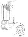
- reaction chamber 40 can be of almost any symmetrical configuration but preferably is tubular or cylindrical in shape as shown.
- Reaction chamber 40 has an inlet 41 at one end for receiving the mixture of fuel and carrier gas and a spaced outlet 42 at its other end for discharging the reactive mixture through reactive mixture duct 12.
- Reaction chamber 40 is connected to ground 44 and functions as an electrode to which power supply 45 is connected and is similar in function to a cathode in a vacuum ion furnace.
- the second electrode is shown as a wire 47 connected to power supply 45 and extending between insulators 48 in reaction chamber 40 and is similar to the anode in a vacuum ion discharge furnace.
- the dielectric particles are zeolites or alternatively (and somewhat preferred), the dielectric particles comprise ferro-electric particles such as barium titanate.
- the particles are placed in a bed and, in the preferred embodiment, are of generally small uniform size. (It is within the concept of the invention to vary the size of the particles through the bed. For example, by means of screens or grids at various bed length positions, different sized particles can be used as the reactive mixture and gas/fuel travels through the bed. Also, inlets and outlets can be staggered along the bed length.)
- the dielectric bed is preferred because, among other reasons, it generates a uniform plasma throughout the bed.
- the dielectric particles 50 function by analogy as capacitors which, when fully charged, prevent the streamers from progressing to the walls of reaction chamber 40 causing arc discharge but in the process of being charged, give off electrons which contribute to the reactions discussed above.
- An AC current supplied by power supply diagrammatically illustrated as reference numeral Figure 51, is sufficient to alternately charge and discharge the capacitive nature of dielectric particles 50 as a function of the frequency of the AC cycle.
- This arrangement alleviates any sophisticated pulsing/arc detect circuit otherwise required in plasma reactors which do not have dielectric particle beds or electrified beds. While such controls are suitable in industrial applications, it is believed they do not lend themselves well to a vehicular environment.
- AC power supply 45 lends itself readily to power increases on demand to vary the plasma intensity, if needed. At the same time, because of the low volume of fuel being processed, there is little energy drain on the vehicle. It is conceptually possible that the load placed on engine 25 by power supply 45 is equivalent to the load placed on the vehicle by its present electrical system. This is an insignificant power drain.
- dielectric particles 50 effectively prevent the formation of petroleum coke when the fuel oil reacts within plasma reaction chamber 40.
- Dielectric particles 50 provide a large effective surface area over which free carbon that forms coke must pass. Accordingly, molecular reactions will likely occur with any free carbon by active oxygen forming volatile materials.
- Plasma reaction chamber 40 can be continuously operated in the preferred embodiment without having to regenerate the bed to rid the bed of coke deposits.
- reaction chamber 40 Surrounding reaction chamber 40 is a heater chamber 60 containing electrically powered heater element 62 for raising and/or maintaining reaction chamber 40 at a desired set temperature. Alternatively, a portion of the exhaust gas can be circulated through heater housing 60 for heating reaction chamber 40 or a combination thereof can be provided. Use of electrical heating elements is preferred.
- the temperature at which diesel fuel is cracked is a function of the space velocity and the catalyst over which the fuel is passed, but, typically speaking, the fuel is cracked at about 500°C.
- the temperature of the plasma reactor is significantly reduced.
- the temperature of reaction chamber 40 does not exceed approximately 300°C and preferably does not exceed temperatures above 200°C.
- One of the primary purposes of heater 62 is to insure the viscosity of the fuel is at a set level as it enters reaction chamber 40 where it can be readily evaporated to gaseous form. If the heat from reaction chamber 40 is insufficient to control the fuel viscosity, heater element 62 will be extended to wrap about the fuel duct leading to reaction chamber 40.
- the oxygen in the carrier gas readily ionizes to react with free carbon to avoid formation of coke.
- the dielectric particles provide a large surface area to assure the reaction.
- the intensity of the plasma and the ratio of the carrier gas and fuel can be variably controlled depending on the NO X emissions produced by engine 25.
- the preferred embodiment of the invention simply sets the carrier gas and fuel at a set ratio with a set plasma intensity to produce a highly reactive mixture, the invention contemplates a variable control depending on engine conditions (mapped or sensed) to produce a specific reactive gas mixture especially suited for NO x reduction based on actual engine operation and emissions.
- reducing catalyst 15 is broadly defined as a lean reducing catalyst as well as NO x absorber catalyst.
- particularly preferred reducing catalysts are composites of zeolites with base metals or platinum (i.e., precious metals group).
- the zeolites within the preferred group can be any of the conventional zeolites but preferred is ZSM-5. While the metal may or may not be crystalline, the zeolites have a crystalline structure exhibiting porosity. Reference can be had to assignee's United States patent Nos. 4,961,917 and 5,516,497 incorporated by reference herein.
- the crystalline structures of zeolites exhibits a complex pore structure having more or less recurring connections, intersections and the like in dimensional planes.
- Preferred zeolites for use in NO catalyst 15 are those which have relatively large diameter pores interconnected within all three crystallographic dimensions, typically about 7-8 Angstroms.
- the invention will function with any zeolite catalyst bed having a porosity of 2-3 angstroms to about 8-10 angstroms.
- An important aspect of a specific feature of the invention is that the reactive gas mixture can be adjusted within the definition of the reactive gas mixture to produce a significant quantity of unbranched, short chain organic molecules which are within the porosity size of the NO catalyst such that a substantial portion of the reactive mixture is able to permeate the catalyst bed increasing the reactive area of the catalyst to enhance NO x reduction.
- the short chain organic molecules are HC oxygenates resulting, in good part, from conversion of branched aliphatic and aromatic by plasma reactor 34.
- the reactive mixture improves the SCR system even for longer chain components of a size which will not permeate the zeolite.
- the invention utilizes a plasma reactor to generate a reducing gas from diesel fuel used by the vehicle.
- the plasma reactor efficiently produces the reducing gas in the harsh vehicular operating environment for use in an SCR system and no additional steps are needed. That is a subsequent plasma treatment of the exhaust gas is not needed.
- the reducing catalyst and producing gas is conventional.
- the plasma reactor is ideally suited to produce the desired reactive mixture defined above. This mixture is more reactive than reducing agents conventionally produced from diesel fuel.
- the system using the reactive gas mixture can use any type of reducing catalyst but a lean catalyst is preferred.
- a species of the reactive gas mixture can be produced by the plasma reactor characterized by having a significant amount of short chain organic molecules able to permeate the porosity of the zeolite bed.
- a still more specific inventive aspect is that the short chain molecules are oxygenated organic molecules having no more than about 3 carbon atoms per molecule.
- the reactive gas mixture as defined above, can be produced by a non-plasma arrangement in which the diesel fuel is reacted in separate stages (i.e., thermal cracking followed by oxidation reactions) to produce the desired mixture.
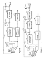
- Oxidation catalyst 22 functions to trim the reactive mixture produced in plasma reactor 34 to produce a substantial amount of desired reactive gas composition. This is accomplished by adding a set quantity of oxygen, either by the addition of EGR gas at duct branch 70, or alternatively, air (or other gas containing oxygen) or alternatively, a metered quantity of air and EGR gas by metering valve 72. Plasma reactor 34 is sized accordingly.
- FIG. 4 a still further embodiment of the invention is disclosed in that conventional thermal cracking unit 19 is applied upstream of plasma reactor 34.
- Oxygen is metered to the cracked fuel leaving cracking unit 19 and the cracked fuel with added oxygen will be subjected to the plasma produced in plasma reactor 34.
- the oxygen can be metered into the cracked fuel either by the direct injection of air, or EGR or combination of EGR and air.
- the plasma produces the oxidated reactive mixture as described with reference to Figure 2. Because the HC chain is cracked in cracking unit 19, the size of plasma reactor unit 34 can be reduced in the Figure 4 embodiment.
- the reactive gas mixture leaving plasma reactor 34 can be directly metered to the exhaust stream through duct 12.
- partial oxidation catalyst 22 can be inserted downstream of plasma reactor 34 and upstream of NO catalyst 15 as shown in Figure 4 and function for the purposes discussed with reference to Figure 3.
- the hydrocarbon reductant is processed in a dedicated plasma reactor or plasma reactor stage to render it a more suitable feedstock for participation in the catalyzed NO x reduction.
- the plasma reactor will importantly serve to cleave the aromatic, long chain, and branched long chain diesel fuel constituents into shorter fragments of greater volatility and of sufficiently reduced molecular dimensions to allow their ready participation.
- Catalyst activity for NO x reduction will be considerably enhanced if the hydrocarbon feedstock is an oxygenated material, particularly a ketone or aldehyde.
- the fuel processor operating conditions are manipulated to maximize the yield of these more reactive materials. This can be done in the plasma reactor itself, particularly with plasma reactors which contain particulate dielectric materials.
- An alternative means to accomplish the desired conversion of diesel fuel or the like into more volatile and reactive components is to employ one or more catalytic reaction stages as part of the fuel processor. The plasma stage would convert the hydrocarbon into a form which would then be brought to the final produce mix composition by the action of the catalytic stage(s).
- the fuel processing of this type offers the considerable advantage that only a very small gas volume containing the hydrocarbon reductant need be treated in the plasma reactor rather than the entire engine exhaust stream. Because the hydrocarbon stream is relatively small, high plasma energy densities and electrical heating of the fuel to accomplish initial evaporation are practical without an onerous consumption of engine output energy. This advantage can be exploited if it is desired to operate one or more stages of the fuel processor at temperatures well above ambient or the internal combustion engine exhaust temperature.
- the plasma fuel processing and any related catalytic stages could readily be incorporated as stages within a larger plasma reactor which treats the entire exhaust stream.
Landscapes
- Engineering & Computer Science (AREA)
- Chemical & Material Sciences (AREA)
- Combustion & Propulsion (AREA)
- Mechanical Engineering (AREA)
- General Engineering & Computer Science (AREA)
- Chemical Kinetics & Catalysis (AREA)
- Health & Medical Sciences (AREA)
- Analytical Chemistry (AREA)
- Environmental & Geological Engineering (AREA)
- General Chemical & Material Sciences (AREA)
- Oil, Petroleum & Natural Gas (AREA)
- Biomedical Technology (AREA)
- Toxicology (AREA)
- Exhaust Gas After Treatment (AREA)
- Exhaust Gas Treatment By Means Of Catalyst (AREA)
- Electrical Control Of Air Or Fuel Supplied To Internal-Combustion Engine (AREA)
- Superconductors And Manufacturing Methods Therefor (AREA)
Applications Claiming Priority (3)
| Application Number | Priority Date | Filing Date | Title |
|---|---|---|---|
| US191697 | 1994-02-04 | ||
| US09/191,697 US6176078B1 (en) | 1998-11-13 | 1998-11-13 | Plasma fuel processing for NOx control of lean burn engines |
| EP99956913A EP1135580B1 (de) | 1998-11-13 | 1999-11-04 | Selektive katalytische reduktion system und verfahren |
Related Parent Applications (1)
| Application Number | Title | Priority Date | Filing Date |
|---|---|---|---|
| EP99956913A Division EP1135580B1 (de) | 1998-11-13 | 1999-11-04 | Selektive katalytische reduktion system und verfahren |
Publications (2)
| Publication Number | Publication Date |
|---|---|
| EP1365119A2 true EP1365119A2 (de) | 2003-11-26 |
| EP1365119A3 EP1365119A3 (de) | 2003-12-10 |
Family
ID=22706573
Family Applications (2)
| Application Number | Title | Priority Date | Filing Date |
|---|---|---|---|
| EP03077728A Withdrawn EP1365119A3 (de) | 1998-11-13 | 1999-11-04 | Plasmabrennstoffverfahren zur NOX Kontrolle von magerbetriebenen Brennkraftmaschinen |
| EP99956913A Expired - Lifetime EP1135580B1 (de) | 1998-11-13 | 1999-11-04 | Selektive katalytische reduktion system und verfahren |
Family Applications After (1)
| Application Number | Title | Priority Date | Filing Date |
|---|---|---|---|
| EP99956913A Expired - Lifetime EP1135580B1 (de) | 1998-11-13 | 1999-11-04 | Selektive katalytische reduktion system und verfahren |
Country Status (6)
| Country | Link |
|---|---|
| US (2) | US6176078B1 (de) |
| EP (2) | EP1365119A3 (de) |
| AT (1) | ATE249576T1 (de) |
| AU (1) | AU1342000A (de) |
| DE (1) | DE69911242T2 (de) |
| WO (1) | WO2000029727A1 (de) |
Cited By (7)
| Publication number | Priority date | Publication date | Assignee | Title |
|---|---|---|---|---|
| EP1479430A1 (de) * | 2003-05-20 | 2004-11-24 | Toyota Jidosha Kabushiki Kaisha | Vorrichtung und Verfahren zur Reinigung von Abgasen |
| DE10337901A1 (de) * | 2003-08-18 | 2005-03-24 | Audi Ag | Verfahren und Vorrichtung zur Synthese von Ammoniak und Verfahren zur Reinigung von Abgasen einer Brennkraftmaschine |
| EP1566525A1 (de) * | 2004-02-19 | 2005-08-24 | General Motors Corporation | Extrem niedriges Leistungsplasmareactorsystem zur Kraftfahrtzeuge Stickoxidausstossüberwachung |
| US7485271B2 (en) | 2003-08-09 | 2009-02-03 | Johnson Matthey Public Limited Company | Catalyst structure for treating NOx containing exhaust gas from a lean burn engine |
| EP1959109A4 (de) * | 2005-12-01 | 2010-11-10 | Toyota Motor Co Ltd | Abgasreiniger für verbrennungsmotor |
| EP1891309A4 (de) * | 2005-06-17 | 2011-02-23 | Gen Motors Global Technology | Kontinuierliche reformierung von dieselkraftstoff für nox-reduktion |
| US8387367B2 (en) | 2005-11-14 | 2013-03-05 | Johnson Matthey Public Limited Company | Reducing coking over Ag/Al2O3 HC-SCR catalyst |
Families Citing this family (161)
| Publication number | Priority date | Publication date | Assignee | Title |
|---|---|---|---|---|
| US6038853A (en) * | 1996-08-19 | 2000-03-21 | The Regents Of The University Of California | Plasma-assisted catalytic storage reduction system |
| DK1017477T3 (da) * | 1997-09-09 | 2001-08-06 | Aea Technology Plc | Behandling af afgasser |
| US6634168B1 (en) * | 1998-10-19 | 2003-10-21 | Nissan Motor Co., Ltd. | Exhaust gas purification system |
| US6560958B1 (en) | 1998-10-29 | 2003-05-13 | Massachusetts Institute Of Technology | Emission abatement system |
| US6176078B1 (en) * | 1998-11-13 | 2001-01-23 | Engelhard Corporation | Plasma fuel processing for NOx control of lean burn engines |
| DE19903533A1 (de) * | 1999-01-29 | 2000-08-10 | Degussa | Verfahren zur selektiven katalytischen Reduktion von Stickoxiden in sauerstoffhaltigen Abgasen |
| AU7823300A (en) * | 1999-06-08 | 2001-01-31 | Bechtel Bwxt Idaho, Llc | Plasma reforming and partial oxidation of hydrocarbon fuel vapor to produce synthesis gas and/or hydrogen gas |
| JP3642273B2 (ja) * | 1999-10-21 | 2005-04-27 | 日産自動車株式会社 | 排気ガス浄化システム |
| GB9924999D0 (en) * | 1999-10-22 | 1999-12-22 | Aea Technology Plc | Reactor for the plasma treatment of gases |
| US6685897B1 (en) * | 2000-01-06 | 2004-02-03 | The Regents Of The University Of California | Highly-basic large-pore zeolite catalysts for NOx reduction at low temperatures |
| US6606856B1 (en) * | 2000-03-03 | 2003-08-19 | The Lubrizol Corporation | Process for reducing pollutants from the exhaust of a diesel engine |
| EP1287242A1 (de) * | 2000-06-01 | 2003-03-05 | Blue Planet Co., Ltd | Vorrichtung zur beseitigung von russ und nox in dieselauslassgas |
| US6363714B1 (en) * | 2000-06-09 | 2002-04-02 | Ford Global Technologies, Inc. | Plasma-catalyst control system |
| US20030084658A1 (en) | 2000-06-20 | 2003-05-08 | Brown Kevin F | Process for reducing pollutants from the exhaust of a diesel engine using a water diesel fuel in combination with exhaust after-treatments |
| JP3398862B2 (ja) * | 2000-07-06 | 2003-04-21 | 本田技研工業株式会社 | 燃料蒸発器の暖機方法 |
| US6557342B2 (en) * | 2000-09-19 | 2003-05-06 | Nissan Motor Co., Ltd. | Exhaust gas purifying system |
| US6729125B2 (en) | 2000-09-19 | 2004-05-04 | Nissan Motor Co., Ltd. | Exhaust gas purifying system |
| US6758036B1 (en) | 2000-10-27 | 2004-07-06 | Delphi Technologies, Inc. | Method for sulfur protection of NOx adsorber |
| US6655130B1 (en) * | 2000-10-30 | 2003-12-02 | Delphi Technologies, Inc. | System and controls for near zero cold start tailpipe emissions in internal combustion engines |
| JP3685052B2 (ja) * | 2000-11-30 | 2005-08-17 | 日産自動車株式会社 | 内燃機関の排気浄化装置 |
| DE10065473A1 (de) * | 2000-12-28 | 2002-07-04 | Basf Ag | Verfahren und Konverter zur katalytischen Umwandlung von Kraftstoff |
| DE10106503A1 (de) * | 2001-02-13 | 2002-08-29 | Bosch Gmbh Robert | Vorrichtung und Verfahren zur nachmotorischen Einbringung eines Hilfsmittels in einen Abgasstrom |
| JP2002292273A (ja) * | 2001-04-02 | 2002-10-08 | Canon Inc | プラズマ反応装置及びプラズマ反応方法 |
| JP3981915B2 (ja) | 2001-04-03 | 2007-09-26 | 日産自動車株式会社 | 排気ガス浄化システム |
| DE10120097B4 (de) * | 2001-04-25 | 2005-07-21 | Daimlerchrysler Ag | Abgasreinigungsanlage und Verfahren zum Betreiben der Anlage |
| US7011790B2 (en) * | 2001-05-07 | 2006-03-14 | Regents Of The University Of Minnesota | Non-thermal disinfection of biological fluids using non-thermal plasma |
| US6562386B2 (en) | 2001-05-07 | 2003-05-13 | Regents Of The University Of Minnesota | Method and apparatus for non-thermal pasteurization |
| US6911225B2 (en) * | 2001-05-07 | 2005-06-28 | Regents Of The University Of Minnesota | Method and apparatus for non-thermal pasteurization of living-mammal-instillable liquids |
| DE10124549A1 (de) * | 2001-05-19 | 2002-11-28 | Degussa | Verfahren zur selektiven katalytischen Reduktion von Stickoxiden mit Ammoniak im mageren Abgas eines Verbrennungsprozesses |
| US6893617B2 (en) * | 2001-06-14 | 2005-05-17 | Delphi Technologies, Inc. | Apparatus and method for retention of non-thermal plasma reactor |
| US7078000B2 (en) * | 2001-06-14 | 2006-07-18 | Delphi Technologies, Inc. | Apparatus and method for mat protection of non-thermal plasma reactor |
| US20030007901A1 (en) * | 2001-07-03 | 2003-01-09 | John Hoard | Method and system for reduction of NOx in automotive vehicle exhaust systems |
| DE10142800A1 (de) * | 2001-08-31 | 2003-03-20 | Bosch Gmbh Robert | Vorrichtung und Verfahren zur Abgasnachbehandlung |
| US20030047146A1 (en) * | 2001-09-10 | 2003-03-13 | Daniel Michael J. | Plasmatron-internal combustion engine system having an independent electrical power source |
| US7165393B2 (en) * | 2001-12-03 | 2007-01-23 | Catalytica Energy Systems, Inc. | System and methods for improved emission control of internal combustion engines |
| US7082753B2 (en) * | 2001-12-03 | 2006-08-01 | Catalytica Energy Systems, Inc. | System and methods for improved emission control of internal combustion engines using pulsed fuel flow |
| DE10161696A1 (de) * | 2001-12-15 | 2003-06-26 | Bayerische Motoren Werke Ag | Verfahren zur katalytischen Abgasnachbehandlung von motorischen Verbrennungsabgasen |
| US20030113249A1 (en) * | 2001-12-18 | 2003-06-19 | Hepburn Jeffrey Scott | System and method for removing SOx and particulate matter from an emission control device |
| US20030118960A1 (en) * | 2001-12-21 | 2003-06-26 | Balmer-Millar Mari Lou | Lean NOx aftertreatment system |
| US6976353B2 (en) * | 2002-01-25 | 2005-12-20 | Arvin Technologies, Inc. | Apparatus and method for operating a fuel reformer to provide reformate gas to both a fuel cell and an emission abatement device |
| US6959542B2 (en) | 2002-01-25 | 2005-11-01 | Arvin Technologies, Inc. | Apparatus and method for operating a fuel reformer to regenerate a DPNR device |
| US7021048B2 (en) * | 2002-01-25 | 2006-04-04 | Arvin Technologies, Inc. | Combination emission abatement assembly and method of operating the same |
| US7014930B2 (en) * | 2002-01-25 | 2006-03-21 | Arvin Technologies, Inc. | Apparatus and method for operating a fuel reformer to generate multiple reformate gases |
| US6810658B2 (en) * | 2002-03-08 | 2004-11-02 | Daimlerchrysler Ag | Exhaust-gas purification installation and exhaust-gas purification method for purifying an exhaust gas from an internal combustion engine |
| US6651597B2 (en) * | 2002-04-23 | 2003-11-25 | Arvin Technologies, Inc. | Plasmatron having an air jacket and method for operating the same |
| WO2003091551A1 (en) * | 2002-04-24 | 2003-11-06 | Arvin Technologies, Inc. | Apparatus and method for regenerating a particulate filter of an exhaust system of an internal combustion engine |
| DE10218232A1 (de) * | 2002-04-24 | 2003-11-06 | Opel Adam Ag | Verfahren und Katalysator zur Verbesserung der Wiksamkeit des zur NOx-Reduktion eingedüsten Dieselkraftstoffes |
| US6895746B2 (en) | 2002-05-31 | 2005-05-24 | Utc Fuel Cells, Llc | Reducing oxides of nitrogen using hydrogen generated from engine fuel and exhaust |
| US20030226350A1 (en) * | 2002-06-11 | 2003-12-11 | Ke Liu | Reducing oxides of nitrogen using reformate generated from engine fuel, water and/or air |
| US20040000475A1 (en) * | 2002-06-27 | 2004-01-01 | Cho Byong Kwon | Plasma reactor having regions of active and passive electric field |
| US20040042947A1 (en) * | 2002-08-28 | 2004-03-04 | John Hoard | Method for NOx reduction |
| CA2536864C (en) * | 2002-08-29 | 2014-01-28 | Paul Rudolf | Associative memory device and method based on wave propagation |
| DE10241065A1 (de) * | 2002-09-05 | 2004-03-11 | Robert Bosch Gmbh | Abgasnachbehandlungsanordnung und Verfahren hierzu |
| DE10241063A1 (de) * | 2002-09-05 | 2004-03-11 | Robert Bosch Gmbh | Verfahren zur Abgasnachbehandlung und Vorrichtung hierzu |
| US20040052693A1 (en) * | 2002-09-18 | 2004-03-18 | Crane Samuel N. | Apparatus and method for removing NOx from the exhaust gas of an internal combustion engine |
| US6758035B2 (en) * | 2002-09-18 | 2004-07-06 | Arvin Technologies, Inc. | Method and apparatus for purging SOX from a NOX trap |
| DE10243269A1 (de) * | 2002-09-18 | 2004-03-25 | Robert Bosch Gmbh | Verfahren zur Abgasnachbehandlung und Vorrichtung hierzu |
| CA2406386C (en) * | 2002-10-02 | 2004-05-18 | Westport Research Inc. | Method and apparatus for regenerating nox adsorbers |
| US6702991B1 (en) | 2002-11-12 | 2004-03-09 | Arvin Technologies, Inc. | Apparatus and method for reducing power consumption of a plasma fuel reformer |
| US6739125B1 (en) * | 2002-11-13 | 2004-05-25 | Collier Technologies, Inc. | Internal combustion engine with SCR and integrated ammonia production |
| WO2004046514A1 (en) * | 2002-11-15 | 2004-06-03 | Catalytica Energy Systems, Inc. | Devices and methods for reduction of nox emissions from lean burn engines |
| US6834498B2 (en) * | 2002-11-21 | 2004-12-28 | Ford Global Technologies, Llc | Diesel aftertreatment systems |
| US6832473B2 (en) * | 2002-11-21 | 2004-12-21 | Delphi Technologies, Inc. | Method and system for regenerating NOx adsorbers and/or particulate filters |
| US6903259B2 (en) * | 2002-12-06 | 2005-06-07 | Arvin Technologies, Inc. | Thermoelectric device for use with fuel reformer and associated method |
| US6959538B2 (en) * | 2002-12-06 | 2005-11-01 | General Motors Corporation | Ultra low power plasma reactor system for automotive NOx emission control |
| US7040084B2 (en) * | 2002-12-16 | 2006-05-09 | General Motors Corporation | Exhaust emission aftertreatment |
| US20040139730A1 (en) * | 2003-01-16 | 2004-07-22 | William Taylor | Method and apparatus for directing exhaust gas and reductant fluid in an emission abatement system |
| US6843054B2 (en) * | 2003-01-16 | 2005-01-18 | Arvin Technologies, Inc. | Method and apparatus for removing NOx and soot from engine exhaust gas |
| US20040144030A1 (en) * | 2003-01-23 | 2004-07-29 | Smaling Rudolf M. | Torch ignited partial oxidation fuel reformer and method of operating the same |
| US7131264B2 (en) * | 2003-01-29 | 2006-11-07 | Delphi Technologies, Inc. | Method of operating a reformer and a vehicle |
| US6851398B2 (en) | 2003-02-13 | 2005-02-08 | Arvin Technologies, Inc. | Method and apparatus for controlling a fuel reformer by use of existing vehicle control signals |
| US7043902B2 (en) * | 2003-03-07 | 2006-05-16 | Honda Motor Co., Ltd. | Exhaust gas purification system |
| JP2004346772A (ja) * | 2003-05-20 | 2004-12-09 | Toyota Motor Corp | 排気浄化装置及び方法 |
| BRPI0411322A (pt) * | 2003-06-12 | 2006-07-18 | Donaldson Co Inc | método de distribuir combustìvel em fluxo transiente de um sistema de descarga |
| US8361404B2 (en) * | 2003-06-20 | 2013-01-29 | Drexel University | Cyclonic reactor with non-equilibrium gliding discharge and plasma process for reforming of solid hydrocarbons |
| WO2004112950A2 (en) * | 2003-06-20 | 2004-12-29 | Drexel University | Plasma reactor for the production of hydrogen-rich gas |
| US8110155B2 (en) | 2003-06-20 | 2012-02-07 | Drexel University | Vortex reactor and method of using it |
| US7000382B2 (en) * | 2003-07-02 | 2006-02-21 | General Motors Corporation | Partial oxidation of alcohols |
| US7413583B2 (en) * | 2003-08-22 | 2008-08-19 | The Lubrizol Corporation | Emulsified fuels and engine oil synergy |
| US7244281B2 (en) | 2003-10-24 | 2007-07-17 | Arvin Technologies, Inc. | Method and apparatus for trapping and purging soot from a fuel reformer |
| US7285247B2 (en) | 2003-10-24 | 2007-10-23 | Arvin Technologies, Inc. | Apparatus and method for operating a fuel reformer so as to purge soot therefrom |
| US7785527B1 (en) | 2003-11-06 | 2010-08-31 | Drexel University | Method of making mixed metal oxide ceramics |
| US20050135977A1 (en) * | 2003-12-19 | 2005-06-23 | Caterpillar Inc. | Multi-part catalyst system for exhaust treatment elements |
| US7541010B2 (en) * | 2003-12-19 | 2009-06-02 | Caterpillar Inc. | Silver doped catalysts for treatment of exhaust |
| US7249455B2 (en) * | 2003-12-23 | 2007-07-31 | Arvin Technologies, Inc. | Method and apparatus for regenerating a nitrogen oxides absorber |
| US20080028754A1 (en) * | 2003-12-23 | 2008-02-07 | Prasad Tumati | Methods and apparatus for operating an emission abatement assembly |
| US7240484B2 (en) * | 2003-12-29 | 2007-07-10 | Delphi Technologies, Inc. | Exhaust treatment systems and methods for using the same |
| US7188469B2 (en) * | 2003-12-29 | 2007-03-13 | Delphi Technologies, Inc. | Exhaust system and methods of reducing contaminants in an exhaust stream |
| US7377101B2 (en) * | 2004-02-13 | 2008-05-27 | Fleetguard, Inc. | Plasma fuel converter NOx adsorber system for exhaust aftertreatment |
| DE102004013165A1 (de) * | 2004-03-17 | 2005-10-06 | Adam Opel Ag | Verfahren zur Verbesserung der Wirksamkeit der NOx-Reduktion in Kraftfahrzeugen |
| US7776265B2 (en) * | 2004-03-18 | 2010-08-17 | Cummins Filtration Ip, Inc. | System for diagnosing reagent solution quality |
| US7454895B2 (en) * | 2004-03-19 | 2008-11-25 | Ford Global Technologies, Llc | Diagnosing an aftertreatment system with a nonthermal plasma discharge device coupled to a lean burn engine |
| US7114324B2 (en) * | 2004-03-19 | 2006-10-03 | Ford Global Technologies, Llc | Method for operating a lean burn engine with an aftertreatment system including nonthermal plasma discharge device |
| US7767163B2 (en) * | 2004-04-20 | 2010-08-03 | Umicore Ag & Co. Kg | Exhaust treatment devices |
| US7153810B2 (en) * | 2004-06-24 | 2006-12-26 | Caterpillar Inc | Silver doped catalysts for treatment of exhaust |
| US7213395B2 (en) * | 2004-07-14 | 2007-05-08 | Eaton Corporation | Hybrid catalyst system for exhaust emissions reduction |
| US7240483B2 (en) * | 2004-08-02 | 2007-07-10 | Eaton Corporation | Pre-combustors for internal combustion engines and systems and methods therefor |
| US7498009B2 (en) * | 2004-08-16 | 2009-03-03 | Dana Uv, Inc. | Controlled spectrum ultraviolet radiation pollution control process |
| US20060043027A1 (en) * | 2004-09-01 | 2006-03-02 | Nguyen Ledu Q | Automotive fluid filter with sintered pellet filter medium and associated method |
| US20060053774A1 (en) * | 2004-09-15 | 2006-03-16 | Kabasin Daniel F | Exhaust treatment system and methods using the same |
| AT501091B1 (de) * | 2004-11-15 | 2006-12-15 | Pankl Emission Control Systems | Abgasreinigungsvorrichtung |
| US20060101810A1 (en) * | 2004-11-15 | 2006-05-18 | Angelo Theodore G | System for dispensing fuel into an exhaust system of a diesel engine |
| JP4151645B2 (ja) * | 2004-11-29 | 2008-09-17 | トヨタ自動車株式会社 | 排ガス浄化装置及びその制御方法 |
| US8006484B2 (en) * | 2005-02-14 | 2011-08-30 | Eaton Corporation | Systems and methods for reducing emissions of internal combustion engines using a fuel processor bypass |
| DE102005017402A1 (de) * | 2005-04-15 | 2006-10-19 | Emitec Gesellschaft Für Emissionstechnologie Mbh | Verfahren und Vorrichtung zur dosierten Bereitstellung eines, insbesondere als Feststoff vorliegenden, Reduktionsmittels für Abgassysteme |
| US7776280B2 (en) * | 2005-05-10 | 2010-08-17 | Emcon Technologies Llc | Method and apparatus for selective catalytic reduction of NOx |
| US20060283176A1 (en) * | 2005-06-17 | 2006-12-21 | Arvinmeritor Emissions Technologies Gmbh | Method and apparatus for regenerating a NOx trap and a particulate trap |
| US7698887B2 (en) * | 2005-06-17 | 2010-04-20 | Emcon Technologies Llc | Method and apparatus for determining local emissions loading of emissions trap |
| US7803338B2 (en) * | 2005-06-21 | 2010-09-28 | Exonmobil Research And Engineering Company | Method and apparatus for combination catalyst for reduction of NOx in combustion products |
| US7743602B2 (en) * | 2005-06-21 | 2010-06-29 | Exxonmobil Research And Engineering Co. | Reformer assisted lean NOx catalyst aftertreatment system and method |
| US7435275B2 (en) * | 2005-08-11 | 2008-10-14 | Delphi Technologies, Inc. | System and method of heating an exhaust treatment device |
| US20070033929A1 (en) * | 2005-08-11 | 2007-02-15 | Arvinmeritor Emissions Technologies Gmbh | Apparatus with in situ fuel reformer and associated method |
| JP4285460B2 (ja) * | 2005-08-24 | 2009-06-24 | トヨタ自動車株式会社 | 内燃機関の排気浄化装置 |
| US7622088B2 (en) * | 2005-09-15 | 2009-11-24 | Gm Global Technology Operations, Inc. | Rapid activation catalyst system in a non-thermal plasma catalytic reactor |
| JP4263711B2 (ja) * | 2005-09-16 | 2009-05-13 | トヨタ自動車株式会社 | 内燃機関の排気浄化装置 |
| US8568662B2 (en) * | 2005-10-10 | 2013-10-29 | Korea Institute Of Machinery And Materials | Plasma reaction apparatus, plasma reaction method using the same, plasma reaction method of persistent gas, and apparatus for decreasing NOx by occlusion catalyst |
| US20070084116A1 (en) * | 2005-10-13 | 2007-04-19 | Bayerische Motoren Werke Aktiengesellschaft | Reformer system having electrical heating devices |
| US7272925B2 (en) * | 2005-10-25 | 2007-09-25 | Gm Global Technology Operations, Inc. | NOx reduction in lean burn engine exhaust |
| US20070095053A1 (en) * | 2005-10-31 | 2007-05-03 | Arvin Technologies, Inc. | Method and apparatus for emissions trap regeneration |
| DE102006043099A1 (de) * | 2005-11-14 | 2007-06-28 | Robert Bosch Gmbh | Luftmengensteuerung für eine Einrichtung zur Erzeugung von Reduktionsmittel |
| US8156732B2 (en) * | 2006-03-24 | 2012-04-17 | Fleetguard, Inc. | Apparatus, system, and method for regenerating an exhaust gas treatment device |
| US7398643B2 (en) * | 2006-05-16 | 2008-07-15 | Dana Canada Corporation | Combined EGR cooler and plasma reactor |
| EP1960639B1 (de) * | 2006-08-01 | 2015-06-17 | Korea Institute Of Machinery & Materials | Reduktionssystem von teilchen in abgasen |
| US7802423B2 (en) * | 2006-08-21 | 2010-09-28 | General Electric Company | Condenser unit for NOx emission reduction system |
| US7587890B2 (en) * | 2006-08-21 | 2009-09-15 | Cummins Inc. | Reductant injection rate shaping method for regeneration of aftertreatment systems |
| US7931811B2 (en) * | 2006-10-27 | 2011-04-26 | Regents Of The University Of Minnesota | Dielectric barrier reactor having concentrated electric field |
| KR100836367B1 (ko) * | 2006-11-21 | 2008-06-09 | 현대자동차주식회사 | 디젤엔진의 입자상물질과 질소산화물 저감을 위한 정화장치 |
| US7891171B2 (en) * | 2006-12-05 | 2011-02-22 | GM Global Technology Operations LLC | Hybrid catalyst for NOx reduction using fuel hydrocarbons as reductant |
| DE102006060471A1 (de) * | 2006-12-19 | 2008-06-26 | J. Eberspächer GmbH & Co. KG | Abgasanlage für eine Brennkraftmaschine |
| US20100018476A1 (en) * | 2007-05-31 | 2010-01-28 | Svetlana Mikhailovna Zemskova | On-board hydrogen generator |
| US8789363B2 (en) | 2007-06-13 | 2014-07-29 | Faurecia Emissions Control Technologies, Usa, Llc | Emission abatement assembly having a mixing baffle and associated method |
| JP2009156063A (ja) * | 2007-12-25 | 2009-07-16 | Toyota Industries Corp | 内燃機関の排ガス処理システム |
| US20090178395A1 (en) * | 2008-01-15 | 2009-07-16 | Huffmeyer Christopher R | Method and Apparatus for Regenerating a Particulate Filter of an Emission Abatement Assembly |
| US20090178391A1 (en) * | 2008-01-15 | 2009-07-16 | Parrish Tony R | Method and apparatus for operating an emission abatement assembly |
| US20090180937A1 (en) * | 2008-01-15 | 2009-07-16 | Nohl John P | Apparatus for Directing Exhaust Flow through a Fuel-Fired Burner of an Emission Abatement Assembly |
| US20090178389A1 (en) * | 2008-01-15 | 2009-07-16 | Crane Jr Samuel N | Method and Apparatus for Controlling a Fuel-Fired Burner of an Emission Abatement Assembly |
| US8776498B2 (en) * | 2008-04-16 | 2014-07-15 | Ford Global Technologies, Llc | Air-injection system to improve effectiveness of selective catalytic reduction catalyst for gasoline engines |
| US20100146947A1 (en) * | 2008-12-16 | 2010-06-17 | General Electric Company | Emissions control system and method |
| WO2010108083A1 (en) * | 2009-03-20 | 2010-09-23 | Basf Catalysts Llc | EMISSIONS TREATMENT SYSTEM WITH LEAN NOx TRAP |
| KR20110012498A (ko) * | 2009-07-30 | 2011-02-09 | 현대자동차주식회사 | 배기 시스템 |
| CN102132019B (zh) * | 2009-09-18 | 2014-05-14 | 光星(株) | 具有旁路系统的选择性催化剂还原系统 |
| US8984886B2 (en) * | 2010-02-12 | 2015-03-24 | General Electric Company | Systems and methods of operating a catalytic reforming assembly for use with a gas turbine engine system |
| US9834442B2 (en) | 2010-03-25 | 2017-12-05 | Drexel University | Gliding arc plasmatron reactor with reverse vortex for the conversion of hydrocarbon fuel into synthesis gas |
| US10920637B2 (en) * | 2012-11-05 | 2021-02-16 | Paradigm Of Ny, Llc | Calibrated non-thermal plasma systems for control of engine emissions |
| US8794217B1 (en) | 2013-02-07 | 2014-08-05 | Thrival Tech, LLC | Coherent-structure fuel treatment systems and methods |
| US9505503B2 (en) * | 2013-03-27 | 2016-11-29 | Lockheed Martin Corporation | Reactants sprayed into plasma flow for rocket propulsion |
| JP6107748B2 (ja) * | 2014-06-20 | 2017-04-05 | 株式会社デンソー | 還元剤添加装置 |
| JP6052257B2 (ja) * | 2014-09-18 | 2016-12-27 | 株式会社デンソー | 還元剤添加装置 |
| DE102014226652A1 (de) | 2014-12-19 | 2016-06-23 | Robert Bosch Gmbh | Abgasnachbehandlungssystem und Verfahren zur Abgasnachbehandlung für eine Brennkraftmaschine |
| DE102014226656A1 (de) * | 2014-12-19 | 2016-06-23 | Robert Bosch Gmbh | Verfahren zum Betreiben eines Abgasnachbehandlungssystems für eine Brennkraftmaschine |
| KR102421531B1 (ko) * | 2015-01-26 | 2022-07-20 | 주식회사 대동 | 배기가스 후처리 장치 및 이를 포함하는 콤바인 |
| JP6376088B2 (ja) * | 2015-09-08 | 2018-08-22 | 株式会社デンソー | オゾン供給装置 |
| US9903248B2 (en) * | 2016-04-13 | 2018-02-27 | GM Global Technology Operations LLC | Method and apparatus for exhaust purification for an internal combustion engine |
| US9926825B2 (en) * | 2016-04-19 | 2018-03-27 | GM Global Technology Operations LLC | Method and apparatus for exhaust purification for an internal combustion engine |
| CN106955585A (zh) * | 2017-03-02 | 2017-07-18 | 海湾环境科技(北京)股份有限公司 | 气体处理方法及系统 |
| US10293303B2 (en) * | 2017-07-28 | 2019-05-21 | Thrivaltech, Llc | Modular plasma reformer treatment system |
| DE102019210413B4 (de) * | 2019-07-15 | 2021-02-18 | Fraunhofer-Gesellschaft zur Förderung der angewandten Forschung e.V. | Abgasnachbehandlung |
| US10914274B1 (en) * | 2019-09-11 | 2021-02-09 | General Electric Company | Fuel oxygen reduction unit with plasma reactor |
| US12115470B2 (en) | 2021-04-27 | 2024-10-15 | General Electric Company | Fuel oxygen reduction unit |
| KR20240038658A (ko) | 2021-06-02 | 2024-03-25 | 리메르, 엘엘씨 | 마이크로파를 이용한 플라즈마 생성 시스템 및 방법 |
| CN114931848B (zh) * | 2022-05-31 | 2023-09-26 | 华南理工大学 | 一种基于低温等离子体的sf6循环降解装置与方法 |
Family Cites Families (28)
| Publication number | Priority date | Publication date | Assignee | Title |
|---|---|---|---|---|
| DE68906508T2 (de) | 1988-10-05 | 1993-09-09 | Mitsubishi Heavy Ind Ltd | Abgasbehandlungsapparat. |
| US5024981A (en) | 1989-04-20 | 1991-06-18 | Engelhard Corporation | Staged metal-promoted zeolite catalysts and method for catalytic reduction of nitrogen oxides using the same |
| US4961917A (en) | 1989-04-20 | 1990-10-09 | Engelhard Corporation | Method for reduction of nitrogen oxides with ammonia using promoted zeolite catalysts |
| US5189876A (en) | 1990-02-09 | 1993-03-02 | Toyota Jidosha Kabushiki Kaisha | Exhaust gas purification system for an internal combustion engine |
| US5343702A (en) | 1990-11-30 | 1994-09-06 | Mitsubishi Jidosha Kokyo Kabushiki Kaisha | Zeolite converter for diesel engine |
| JPH04243525A (ja) | 1991-01-22 | 1992-08-31 | Toyota Motor Corp | 内燃機関の排気浄化装置 |
| EP0679427A1 (de) * | 1991-07-23 | 1995-11-02 | Kabushiki Kaisha Riken | Abgasreiniger |
| US5534237A (en) * | 1991-07-23 | 1996-07-09 | Kubushiki Kaisha Riken | Method of cleaning an exhaust gas and exhaust gas cleaner therefor |
| US5208205A (en) | 1991-10-07 | 1993-05-04 | Ford Motor Company | Catalyst system for converting emissions of a lean-burn engine |
| JP2850689B2 (ja) * | 1993-01-14 | 1999-01-27 | 三菱自動車工業株式会社 | 排気ガス浄化装置 |
| GB9301433D0 (en) | 1993-01-20 | 1993-03-17 | Atomic Energy Authority Uk | Gas purification |
| DE4404617C2 (de) | 1994-02-14 | 1998-11-05 | Daimler Benz Ag | Vorrichtung zur selektiven katalysierten NO¶x¶-Reduktion in sauerstoffhaltigen Abgasen von Brennkraftmaschinen |
| DE4416676C2 (de) * | 1994-05-11 | 2002-11-07 | Siemens Ag | Vorrichtung zur Entgiftung von Abgasen aus mobilen Anlagen |
| DE19510804A1 (de) | 1995-03-24 | 1996-09-26 | Dornier Gmbh | Verfahren und Vorrichtung zur Stickoxidminderung in Abgasen von Verbrennungsmaschinen |
| JPH0913955A (ja) | 1995-06-27 | 1997-01-14 | Komatsu Ltd | ディーゼルエンジンの排気ガス浄化装置 |
| US5746984A (en) | 1996-06-28 | 1998-05-05 | Low Emissions Technologies Research And Development Partnership | Exhaust system with emissions storage device and plasma reactor |
| US5891409A (en) | 1996-08-19 | 1999-04-06 | The Regents Of The University Of California | Pre-converted nitric oxide gas in catalytic reduction system |
| US6038853A (en) * | 1996-08-19 | 2000-03-21 | The Regents Of The University Of California | Plasma-assisted catalytic storage reduction system |
| US5711147A (en) | 1996-08-19 | 1998-01-27 | The Regents Of The University Of California | Plasma-assisted catalytic reduction system |
| US5807466A (en) | 1996-08-19 | 1998-09-15 | Hughes Electronics | Fuel injection system and method for treatment of NOx in a corona discharge pollutant destruction apparatus |
| US5715677A (en) | 1996-11-13 | 1998-02-10 | The Regents Of The University Of California | Diesel NOx reduction by plasma-regenerated absorbend beds |
| US6047543A (en) * | 1996-12-18 | 2000-04-11 | Litex, Inc. | Method and apparatus for enhancing the rate and efficiency of gas phase reactions |
| US5767470A (en) | 1997-01-06 | 1998-06-16 | Cha; Chang Yul | Process and device for removal of combustion pollutants under high oxygen conditions |
| DK0988104T3 (da) | 1997-05-16 | 2002-11-18 | Siemens Ag | Fremgangsmåder og indretning til tilintetgørelse af skadelige oxidstoffer i en oxygenholdig røggas samt dermed drevet motor |
| GB9715409D0 (en) | 1997-07-23 | 1997-09-24 | Aea Technology Plc | Gas purification |
| DK1017477T3 (da) | 1997-09-09 | 2001-08-06 | Aea Technology Plc | Behandling af afgasser |
| GB9801775D0 (en) | 1998-01-29 | 1998-03-25 | Aea Technology Plc | Gas purification |
| US6176078B1 (en) * | 1998-11-13 | 2001-01-23 | Engelhard Corporation | Plasma fuel processing for NOx control of lean burn engines |
-
1998
- 1998-11-13 US US09/191,697 patent/US6176078B1/en not_active Expired - Fee Related
-
1999
- 1999-11-04 DE DE69911242T patent/DE69911242T2/de not_active Expired - Fee Related
- 1999-11-04 EP EP03077728A patent/EP1365119A3/de not_active Withdrawn
- 1999-11-04 AT AT99956913T patent/ATE249576T1/de not_active IP Right Cessation
- 1999-11-04 WO PCT/US1999/026043 patent/WO2000029727A1/en not_active Ceased
- 1999-11-04 EP EP99956913A patent/EP1135580B1/de not_active Expired - Lifetime
- 1999-11-04 AU AU13420/00A patent/AU1342000A/en not_active Abandoned
-
2000
- 2000-11-07 US US09/707,594 patent/US6363716B1/en not_active Expired - Fee Related
Cited By (7)
| Publication number | Priority date | Publication date | Assignee | Title |
|---|---|---|---|---|
| EP1479430A1 (de) * | 2003-05-20 | 2004-11-24 | Toyota Jidosha Kabushiki Kaisha | Vorrichtung und Verfahren zur Reinigung von Abgasen |
| US7485271B2 (en) | 2003-08-09 | 2009-02-03 | Johnson Matthey Public Limited Company | Catalyst structure for treating NOx containing exhaust gas from a lean burn engine |
| DE10337901A1 (de) * | 2003-08-18 | 2005-03-24 | Audi Ag | Verfahren und Vorrichtung zur Synthese von Ammoniak und Verfahren zur Reinigung von Abgasen einer Brennkraftmaschine |
| EP1566525A1 (de) * | 2004-02-19 | 2005-08-24 | General Motors Corporation | Extrem niedriges Leistungsplasmareactorsystem zur Kraftfahrtzeuge Stickoxidausstossüberwachung |
| EP1891309A4 (de) * | 2005-06-17 | 2011-02-23 | Gen Motors Global Technology | Kontinuierliche reformierung von dieselkraftstoff für nox-reduktion |
| US8387367B2 (en) | 2005-11-14 | 2013-03-05 | Johnson Matthey Public Limited Company | Reducing coking over Ag/Al2O3 HC-SCR catalyst |
| EP1959109A4 (de) * | 2005-12-01 | 2010-11-10 | Toyota Motor Co Ltd | Abgasreiniger für verbrennungsmotor |
Also Published As
| Publication number | Publication date |
|---|---|
| DE69911242T2 (de) | 2004-07-08 |
| US6176078B1 (en) | 2001-01-23 |
| DE69911242D1 (de) | 2003-10-16 |
| US6363716B1 (en) | 2002-04-02 |
| ATE249576T1 (de) | 2003-09-15 |
| AU1342000A (en) | 2000-06-05 |
| EP1365119A3 (de) | 2003-12-10 |
| WO2000029727A1 (en) | 2000-05-25 |
| EP1135580B1 (de) | 2003-09-10 |
| EP1135580A1 (de) | 2001-09-26 |
Similar Documents
| Publication | Publication Date | Title |
|---|---|---|
| US6363716B1 (en) | Plasma fuel processing for NOx control lean burn engines | |
| EP1309390B1 (de) | Verfahren und vorrichtung zur entfernung von stickoxiden im abgas einer brennkraftmaschine | |
| KR100818681B1 (ko) | 디젤엔진 배기가스내 NOx의 환원방법 | |
| Penetrante et al. | Plasma-assisted catalytic reduction of NO x | |
| US6557340B1 (en) | System and method for purifying exhaust gases | |
| US6247303B1 (en) | Method and device for removing oxidic noxious substances in an oxygen-containing exhaust gas and engine which is operated therewith | |
| EP1274504B1 (de) | Plasmaunterstützte gasbehandlung | |
| US6775972B2 (en) | Purification of exhaust gases | |
| US7198764B2 (en) | Gas treatment system and a method for using the same | |
| US7121079B2 (en) | System for exhaust gas treatment comprising a gas ionizing system with ionized air injection | |
| RU2592791C2 (ru) | СПОСОБ ОБРАБОТКИ NOx ВЫХЛОПНЫХ ГАЗОВ С ИСПОЛЬЗОВАНИЕМ ТРЕХ ПОСЛЕДОВАТЕЛЬНЫХ ЗОН КАТАЛИЗАТОРОВ SCR | |
| EP1149231A2 (de) | Verfahren und reaktor zur plasmagestüzten gasbehandlung | |
| EP1077078A2 (de) | System zum Umsetzen von Teilchen im Abgas eines Benzinmotors | |
| US9376948B2 (en) | Vehicle and method of treating an exhaust gas | |
| Pospisil et al. | Application of plasma techniques for exhaust aftertreatment | |
| KR100444914B1 (ko) | 디젤엔진 배출가스의 질소산화물을 선택적으로 제거하기위한 플라즈마/금촉매 시스템 | |
| KR20000006954U (ko) | 유해 배기가스 저감형 자동차의 배기장치 | |
| Voss et al. | Plasma-assisted catalytic reduction of NOx | |
| Itoh et al. | NOx Reduction under oxidizing conditions by plasma-assisted catalysis | |
| Song et al. | A Combined De-NOx Process with NH, SCR and Non | |
| SITTICHOMPOO et al. | The Promotion of NO to NO2 in Diesel Exhaust Gas by Dielectric Barrier Discharge Non-thermal Plasma Method |
Legal Events
| Date | Code | Title | Description |
|---|---|---|---|
| PUAI | Public reference made under article 153(3) epc to a published international application that has entered the european phase |
Free format text: ORIGINAL CODE: 0009012 |
|
| PUAL | Search report despatched |
Free format text: ORIGINAL CODE: 0009013 |
|
| AC | Divisional application: reference to earlier application |
Ref document number: 1135580 Country of ref document: EP Kind code of ref document: P |
|
| AK | Designated contracting states |
Kind code of ref document: A2 Designated state(s): AT BE CH CY DE DK ES FI FR GB GR IE IT LI LU MC NL PT SE |
|
| AK | Designated contracting states |
Kind code of ref document: A3 Designated state(s): AT BE CH CY DE DK ES FI FR GB GR IE IT LI LU MC NL PT SE |
|
| AKX | Designation fees paid | ||
| REG | Reference to a national code |
Ref country code: DE Ref legal event code: 8566 |
|
| STAA | Information on the status of an ep patent application or granted ep patent |
Free format text: STATUS: THE APPLICATION IS DEEMED TO BE WITHDRAWN |
|
| 18D | Application deemed to be withdrawn |
Effective date: 20040611 |