EP1365150B1 - Verdrängungsverdichter ohne taumelscheibenkupplung - Google Patents
Verdrängungsverdichter ohne taumelscheibenkupplung Download PDFInfo
- Publication number
- EP1365150B1 EP1365150B1 EP01948010.2A EP01948010A EP1365150B1 EP 1365150 B1 EP1365150 B1 EP 1365150B1 EP 01948010 A EP01948010 A EP 01948010A EP 1365150 B1 EP1365150 B1 EP 1365150B1
- Authority
- EP
- European Patent Office
- Prior art keywords
- valve
- check valve
- seating surface
- swash plate
- discharge check
- Prior art date
- Legal status (The legal status is an assumption and is not a legal conclusion. Google has not performed a legal analysis and makes no representation as to the accuracy of the status listed.)
- Expired - Lifetime
Links
- 238000006073 displacement reaction Methods 0.000 title 1
- 239000003507 refrigerant Substances 0.000 claims description 38
- 230000006835 compression Effects 0.000 claims description 5
- 238000007906 compression Methods 0.000 claims description 5
- 230000002093 peripheral effect Effects 0.000 description 24
- 238000010276 construction Methods 0.000 description 14
- 238000001816 cooling Methods 0.000 description 10
- 230000000694 effects Effects 0.000 description 8
- 244000145845 chattering Species 0.000 description 5
- 238000004891 communication Methods 0.000 description 3
- 230000007423 decrease Effects 0.000 description 3
- 238000005461 lubrication Methods 0.000 description 3
- 125000006850 spacer group Chemical group 0.000 description 3
- 230000003247 decreasing effect Effects 0.000 description 2
- 230000001050 lubricating effect Effects 0.000 description 2
- 239000000696 magnetic material Substances 0.000 description 2
- 238000000034 method Methods 0.000 description 2
- 230000010349 pulsation Effects 0.000 description 2
- 238000011144 upstream manufacturing Methods 0.000 description 2
- 238000005452 bending Methods 0.000 description 1
- 230000015572 biosynthetic process Effects 0.000 description 1
- 230000000903 blocking effect Effects 0.000 description 1
- 230000001419 dependent effect Effects 0.000 description 1
- 238000007710 freezing Methods 0.000 description 1
- 230000008014 freezing Effects 0.000 description 1
- 238000004519 manufacturing process Methods 0.000 description 1
- 239000000463 material Substances 0.000 description 1
Images







Classifications
-
- F—MECHANICAL ENGINEERING; LIGHTING; HEATING; WEAPONS; BLASTING
- F04—POSITIVE - DISPLACEMENT MACHINES FOR LIQUIDS; PUMPS FOR LIQUIDS OR ELASTIC FLUIDS
- F04B—POSITIVE-DISPLACEMENT MACHINES FOR LIQUIDS; PUMPS
- F04B49/00—Control, e.g. of pump delivery, or pump pressure of, or safety measures for, machines, pumps, or pumping installations, not otherwise provided for, or of interest apart from, groups F04B1/00 - F04B47/00
- F04B49/22—Control, e.g. of pump delivery, or pump pressure of, or safety measures for, machines, pumps, or pumping installations, not otherwise provided for, or of interest apart from, groups F04B1/00 - F04B47/00 by means of valves
-
- F—MECHANICAL ENGINEERING; LIGHTING; HEATING; WEAPONS; BLASTING
- F04—POSITIVE - DISPLACEMENT MACHINES FOR LIQUIDS; PUMPS FOR LIQUIDS OR ELASTIC FLUIDS
- F04B—POSITIVE-DISPLACEMENT MACHINES FOR LIQUIDS; PUMPS
- F04B27/00—Multi-cylinder pumps specially adapted for elastic fluids and characterised by number or arrangement of cylinders
- F04B27/08—Multi-cylinder pumps specially adapted for elastic fluids and characterised by number or arrangement of cylinders having cylinders coaxial with, or parallel or inclined to, main shaft axis
- F04B27/14—Control
- F04B27/16—Control of pumps with stationary cylinders
- F04B27/18—Control of pumps with stationary cylinders by varying the relative positions of a swash plate and a cylinder block
- F04B27/1804—Controlled by crankcase pressure
-
- F—MECHANICAL ENGINEERING; LIGHTING; HEATING; WEAPONS; BLASTING
- F04—POSITIVE - DISPLACEMENT MACHINES FOR LIQUIDS; PUMPS FOR LIQUIDS OR ELASTIC FLUIDS
- F04B—POSITIVE-DISPLACEMENT MACHINES FOR LIQUIDS; PUMPS
- F04B49/00—Control, e.g. of pump delivery, or pump pressure of, or safety measures for, machines, pumps, or pumping installations, not otherwise provided for, or of interest apart from, groups F04B1/00 - F04B47/00
- F04B49/22—Control, e.g. of pump delivery, or pump pressure of, or safety measures for, machines, pumps, or pumping installations, not otherwise provided for, or of interest apart from, groups F04B1/00 - F04B47/00 by means of valves
- F04B49/24—Bypassing
- F04B49/246—Bypassing by keeping open the outlet valve
-
- F—MECHANICAL ENGINEERING; LIGHTING; HEATING; WEAPONS; BLASTING
- F16—ENGINEERING ELEMENTS AND UNITS; GENERAL MEASURES FOR PRODUCING AND MAINTAINING EFFECTIVE FUNCTIONING OF MACHINES OR INSTALLATIONS; THERMAL INSULATION IN GENERAL
- F16K—VALVES; TAPS; COCKS; ACTUATING-FLOATS; DEVICES FOR VENTING OR AERATING
- F16K15/00—Check valves
- F16K15/02—Check valves with guided rigid valve members
- F16K15/025—Check valves with guided rigid valve members the valve being loaded by a spring
- F16K15/026—Check valves with guided rigid valve members the valve being loaded by a spring the valve member being a movable body around which the medium flows when the valve is open
-
- F—MECHANICAL ENGINEERING; LIGHTING; HEATING; WEAPONS; BLASTING
- F16—ENGINEERING ELEMENTS AND UNITS; GENERAL MEASURES FOR PRODUCING AND MAINTAINING EFFECTIVE FUNCTIONING OF MACHINES OR INSTALLATIONS; THERMAL INSULATION IN GENERAL
- F16K—VALVES; TAPS; COCKS; ACTUATING-FLOATS; DEVICES FOR VENTING OR AERATING
- F16K17/00—Safety valves; Equalising valves, e.g. pressure relief valves
- F16K17/02—Safety valves; Equalising valves, e.g. pressure relief valves opening on surplus pressure on one side; closing on insufficient pressure on one side
- F16K17/04—Safety valves; Equalising valves, e.g. pressure relief valves opening on surplus pressure on one side; closing on insufficient pressure on one side spring-loaded
- F16K17/06—Safety valves; Equalising valves, e.g. pressure relief valves opening on surplus pressure on one side; closing on insufficient pressure on one side spring-loaded with special arrangements for adjusting the opening pressure
-
- F—MECHANICAL ENGINEERING; LIGHTING; HEATING; WEAPONS; BLASTING
- F16—ENGINEERING ELEMENTS AND UNITS; GENERAL MEASURES FOR PRODUCING AND MAINTAINING EFFECTIVE FUNCTIONING OF MACHINES OR INSTALLATIONS; THERMAL INSULATION IN GENERAL
- F16K—VALVES; TAPS; COCKS; ACTUATING-FLOATS; DEVICES FOR VENTING OR AERATING
- F16K47/00—Means in valves for absorbing fluid energy
- F16K47/02—Means in valves for absorbing fluid energy for preventing water-hammer or noise
-
- F—MECHANICAL ENGINEERING; LIGHTING; HEATING; WEAPONS; BLASTING
- F04—POSITIVE - DISPLACEMENT MACHINES FOR LIQUIDS; PUMPS FOR LIQUIDS OR ELASTIC FLUIDS
- F04B—POSITIVE-DISPLACEMENT MACHINES FOR LIQUIDS; PUMPS
- F04B27/00—Multi-cylinder pumps specially adapted for elastic fluids and characterised by number or arrangement of cylinders
- F04B27/08—Multi-cylinder pumps specially adapted for elastic fluids and characterised by number or arrangement of cylinders having cylinders coaxial with, or parallel or inclined to, main shaft axis
- F04B27/14—Control
- F04B27/16—Control of pumps with stationary cylinders
- F04B27/18—Control of pumps with stationary cylinders by varying the relative positions of a swash plate and a cylinder block
- F04B27/1804—Controlled by crankcase pressure
- F04B2027/1863—Controlled by crankcase pressure with an auxiliary valve, controlled by
- F04B2027/1872—Discharge pressure
Definitions
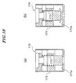
- valve-opening pressure of the discharge check valve 170 when the valve-opening pressure of the discharge check valve 170 is high, differential pressure across the discharge check valve becomes small during the ON time of the air conditioner and in low-speed operation of the compressor, and hence the discharge check valve 170 is closed due to the differential pressure yielding to the spring force of a spring 173.
- the discharge check valve 170 When the discharge check valve 170 is closed, pressure is trapped in the compressor, and then the trapped pressure opens the valve. Thus, the opening and closing of the discharge check valve 170 is repeated, which causes discharge pulsation.
- An object of the invention is to provide a clutchless variable capacity swash plate compressor which is capable of sufficiently lubricating and cooling sliding portions of the compressor even when an engine performs high-speed rotation during the OFF time of an air conditioner, and suppressing occurrence of chattering of a discharge check valve e.g. when the air conditioner is in the ON state and cooling load is low.
- the discharge check valve whose valve-closing pressure is lower than its valve-opening pressure is provided. Therefore, even if the valve-opening pressure is set such that the discharge check valve does not open when the air conditioner is in an OFF state and the engine rotates at high speed, since the valve-closing pressure is lower than the valve-opening pressure, the discharge check valve does not close when the air conditioner is in an ON state and cooling load is small. This makes it possible to prevent chattering of the discharge check valve e.g. when the cooling load is low.
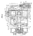
- the front head 4 defines therein a crankcase 8 in which a swash plate 10 is received.
- the front head 4 has a boss 4a projecting from a central portion thereof.
- a radial bearing 26 and a shaft seal 27 are received in the boss 4a.
- the suction check valve 120 is comprised of a valve seat 121, a casing 122, a valve element 123, and a spring 124.
- the front end portion of the shaft 5 is rotatably supported by a radial bearing 26.
- a gap between the outer peripheral portion of the front end portion of the shaft 5 and the boss 4a is sealed by a shaft seal 27.
- the shaft 5 has a rear end portion thereof formed with a stepped surface 5a on which a thrust bearing 24 is fitted.
- the rear end portion of the shaft 5 is inserted into a radial bearing 25 fitted in the central hole 1a of the cylinder block 1.
- the rear end portion of the shaft 5 is supported by the thrust bearing 24 and the radial bearing 25.
- the shaft 5 is formed with a passage 5b.
- the passage 5b communicates between a bearing-receiving space of the boss 4a and the central hole 1a of the cylinder bore 1.
- the compression chamber 6a, the refrigerant outlet port 16, the air supply passage 57, the crankcase 8, the bearing-receiving space of the boss 4a, the passage 5b,the passage 58, and the orifice 2a form an internal circulation passage.
- This internal circulation passage causes refrigerant gas to circulate within a housing of the compressor when the inclination angle of the swash plate 10 is the minimum or close to the minimum, thereby lubricating and cooling sliding portions of the compressor.
- a snap ring (inclination angle-limiting member) 51 for receiving the hinge ball 9 to thereby determine a minimum inclination angle of the swash plate 10.
- a spacer (inclination angle-adjusting member) 52 for adjusting the minimum inclination angle of the swash plate 10 is disposed on the hinge ball-side end face of the snap ring 51.
- the spacer 52 is selected from a plurality of spacers 52 during assembly of the compressor, and used so as to accommodate variations among component parts, whereby the minimum inclination angle of the swash plate 10 is adjusted and controlled to a predetermined value.
- the hollow cylindrical portion 1c has a cover 11 mounted thereon via the baffle plate 14.
- the cover 11 is formed with a discharge port 11a and a valve-receiving hole 11b.
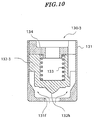
- the casing 131 is in the form of a bottomed hollow cylinder. As shown in FIG. 5 , the casing 131 is comprised of a bottom portion 131a, an overlapping portion 131b, a lift portion 131c, and a hollow cylindrical portion 131d.
- the bottom potion 131a has a first seating surface 131e and a circular through hole 131f formed in the central portion of the first seating surface 131e.
- the overlapping portion 131b is formed in a manner continuous with the bottom portion 131a, and an end of the valve element 132 is fitted in the overlapping portion 131b over a predetermined length in the direction of depth of the casing 131.
- the lift portion 131c is formed in a manner continuous with the overlapping portion 131b, and has a tapered surface 131g that cooperates with the end of the valve element 132 to restrict the flow of refrigerant gas.
- the tapered surface 131g expands as the distance from the first seating surface 131e increases.
- the hollow cylindrical portion 131d is formed in a manner continuous with the lift portion 131c, for guiding the valve element 132 along the direction of depth of the casing 131.
- the spring 133 is disposed within the casing 131, for urging the valve element 132 toward the bottom portion 131a of the casing 131.
- the stopper 134 is fixed in the casing 131, for limiting the motion of the valve element 132.
- the stopper 134 is comprised of a body 134a, a holding portion 134, and a plurality of leg portions 134c.
- the body 134a is generally in the form of a ring.
- the holding portion 134b is in the form of a ring and formed on an end face of the body 134a.
- the spring 133 is held by the holding portion 134b.
- the leg portions 134c are provided on the outer peripheral surface of the body 134a at predetermined circumferential intervals. The leg portions 134c are fixedly secured on the inner peripheral surface of the hollow cylindrical portion 131d of the casing 131, whereby the stopper 134 is fixed in the casing 131.
- FIG. 8 is an exploded perspective view of a discharge check valve provided in a clutchless variable capacity swash plate compressor according to a second embodiment of the present invention
- FIG. 9 illustrates a valve element of the FIG. 8 discharge check valve, in which FIG. 9(a) is a plan view thereof, and FIG. 9(b) is a cross-sectional view taken on line II-II.
Landscapes
- Engineering & Computer Science (AREA)
- General Engineering & Computer Science (AREA)
- Mechanical Engineering (AREA)
- Compressors, Vaccum Pumps And Other Relevant Systems (AREA)
- Compressor (AREA)
Claims (7)
- Kupplungsloser Taumelscheibenkompressor mit variablem Hub, umfassend:eine Welle (5), drehbar gestützt in einem Kompressorgehäuse;eine Taumelscheibe (10), kippbar montiert an der Welle (5) zur gemeinsamen Drehung damit; undeinen Ausstoßdurchtritt (D), über welchen Kältemittelgas, geliefert von einer Kompressionskammer (6a) zu einer Ausstoßkammer (12) aus dem Kompressor geleitet ist/wird;ein Rückschlagventil (130), bereitgestellt in dem Ausstoßdurchgang (D), wobei das Ausstoßrückschlagventil (130) über einen Ventilschließdruck verfügt, eingestellt auf einen Wert niedriger als einen Ventilöffnungsdruck,dadurch gekennzeichnet, dass das Ausstoßrückschlagventil ein bodenaufweisendes hohles zylindrisches Gehäuse (131), ein Ventilelement (132), gleitfähig in dem Gehäuse (131) entlang einer Richtung einer Tiefe des Gehäuses (131), und eine Feder (133) zum Beaufschlagen des Ventilelementes (132) in einer Richtung eines Bodens (131a) des Gehäuses (131) umfasst, wobei das Gehäuse (131) eine erste Sitzfläche (131e) aufweist, ausgebildet an dem Boden (131a), ein Loch (131f), ausgebildet in einer Mitte der ersten Sitzfläche (131e), einen Überlappungsabschnitt (131b), ausgebildet in einer Weise kontinuierlich mit dem Boden (131a), um gepasst zu sein an einem Ende des Ventilelementes (132), über eine vorbestimmte Länge in der Richtung der Tiefe, und einen hohlen zylindrischen Abschnitt (131d), ausgebildet in einer Weise kontinuierlich mit dem Überlappungsabschnitt (131b) zum Führen des Ventilelementes (132) entlang der Richtung der Tiefe, wobei das Ventilelement (132) eine zweite Sitzfläche (132e) aufweist, gebildet an einer Endfläche davon zum Öffnen und Schließen des Loches (131f).
- Kupplungsloser Taumelscheibenkompressor mit variablem Hub nach Anspruch 1, bei welchem der Überlappungsabschnitt (131b) und der hohle zylindrische Abschnitt (131d) in einer kontinuierlichen Weise mit Bezug zueinander über eine abgeschrägte oder sich verjüngende Fläche (131g) ausgebildet sind.
- Kupplungsloser Taumelscheibenkompressor mit variablem Hub nach Anspruch 1 oder 2, umfassend einen Anschlag (134) zur Bewegungseinschränkung des Ventilelementes (132).
- Kupplungsloser Taumelscheibenkompressor mit variablem Hub nach Anspruch 1, 2 oder 3, bei welchem das Ventilelement (132) eine gestufte oder abgestufte Fläche (132d) aufweist, welche die zweite Sitzfläche (132c) umgibt oder umrundet und einen Raum bildet in welchem Druck hinter dem Ventilelement (132) eingeführt ist/wird zwischen die gestufte Fläche (132d) und die erste Sitzfläche, wenn die zweite Sitzfläche in Berührung steht mit der ersten Sitzfläche (131e).
- Kupplungsloser Taumelscheibenkompressor mit variablem Hub nach einem der Ansprüche 1 bis 4, bei welchem das Ausstoßrückschlagventil (130) über zumindest eine Ventilöffnungsverzögerungseinrichtung verfügt zur Verzögerung der Ventilöffnung davon um somit einen Ventilschließdruck geringer zu gestalten als einen Ventilöffnungsdruck davon, sowie über eine Ventilverschlussverzögerungseinrichtung zur Ventilverschlussverzögerung um somit den Ventilverschlussdruck davon geringer zu gestalten als den Ventilöffnungsdruck davon.
- Kupplungsloser Taumelscheibenkompressor mit variablem Hub nach einem der Ansprüche 1 bis 5, bei welchem das Ausstoßrückschlagventil (130) über eine Ventilöffnungsverzögerungseinrichtung verfügt zur Ventilöffnungsverzögerung davon, wobei die Ventilöffnungsverzögerungseinrichtung gebildet ist durch die erste Sitzfläche (131e), gebildet an dem einem Ende des Gehäuses (131), das Loch (131f), gebildet in der ersten Sitzfläche (131e) und die zweite Sitzfläche (132e), gebildet an dem Ventilelement (132) in einer Weise gegenüberstehend zu dem Loch (131f), wobei die zweite Sitzfläche (132e) kleiner ist als die erste Sitzfläche (131e) und größer als das Loch.
- Kupplungsloser Taumelscheibenkompressor mit variablem Hub nach einem der Ansprüche 1 bis 6, bei welchem das Ausstoßrückschlagventil (130) über eine Schließverzögerungseinrichtung verfügt zur Verzögerung des Ventilschließens davon, wobei die Ventilschließverzögerungseinrichtung gebildet ist durch die erste Sitzfläche (131e), gebildet an dem einen Ende des Gehäuses (131), das Loch (131f), gebildet in der ersten Sitzfläche (131e) und den Überlappungsabschnitt (131b), gebildet in dem Gehäuse (131) in einer Weise, die erste Sitzfläche (131e) umgebend oder umschließend um das Ende des Ventilelementes (132) gepasst darin in einer Richtung der Tiefe zu haben.
Applications Claiming Priority (3)
| Application Number | Priority Date | Filing Date | Title |
|---|---|---|---|
| JP2001019443 | 2001-01-29 | ||
| JP2001019443 | 2001-01-29 | ||
| PCT/JP2001/006097 WO2002061280A1 (en) | 2001-01-29 | 2001-07-13 | Variable displacement type swash plate clutch-less compressor |
Publications (3)
| Publication Number | Publication Date |
|---|---|
| EP1365150A1 EP1365150A1 (de) | 2003-11-26 |
| EP1365150A4 EP1365150A4 (de) | 2006-06-07 |
| EP1365150B1 true EP1365150B1 (de) | 2016-08-24 |
Family
ID=18885319
Family Applications (1)
| Application Number | Title | Priority Date | Filing Date |
|---|---|---|---|
| EP01948010.2A Expired - Lifetime EP1365150B1 (de) | 2001-01-29 | 2001-07-13 | Verdrängungsverdichter ohne taumelscheibenkupplung |
Country Status (5)
| Country | Link |
|---|---|
| US (1) | US20040062660A1 (de) |
| EP (1) | EP1365150B1 (de) |
| JP (1) | JP4655260B2 (de) |
| DE (1) | DE20122730U1 (de) |
| WO (1) | WO2002061280A1 (de) |
Families Citing this family (29)
| Publication number | Priority date | Publication date | Assignee | Title |
|---|---|---|---|---|
| JP4734623B2 (ja) * | 2003-09-24 | 2011-07-27 | 株式会社ヴァレオジャパン | 可変容量型クラッチレス圧縮機 |
| JP2006200552A (ja) * | 2005-01-18 | 2006-08-03 | Fuji Koki Corp | 逆止弁 |
| JP4826948B2 (ja) * | 2005-10-06 | 2011-11-30 | 株式会社ヴァレオジャパン | ピストン型圧縮機 |
| JP4330576B2 (ja) * | 2005-10-28 | 2009-09-16 | サンデン株式会社 | 圧縮機 |
| JP5240535B2 (ja) * | 2006-01-30 | 2013-07-17 | 株式会社ヴァレオジャパン | 可変容量型クラッチレス圧縮機 |
| JP2009191754A (ja) * | 2008-02-15 | 2009-08-27 | Toyota Industries Corp | 可変容量ギヤポンプ |
| DE102008060146A1 (de) * | 2008-12-03 | 2010-06-17 | Thyssenkrupp Presta Ag | Rückschlagventil für eine hydraulische Servolenkung |
| GB2478876B (en) * | 2009-03-31 | 2012-03-21 | Scion Sprays Ltd | A fluid injector having a novel inlet valve arrangement |
| US8196506B2 (en) * | 2009-08-17 | 2012-06-12 | Delphi Technologies, Inc. | Variable stroke compressor design |
| US20110116940A1 (en) * | 2009-11-17 | 2011-05-19 | Cameron International Corporation | Viscoelastic compressor pulsation dampener |
| CN102918286B (zh) | 2010-03-09 | 2016-04-06 | 大丰工业株式会社 | 滑动部件 |
| JP5494802B2 (ja) * | 2010-05-15 | 2014-05-21 | 株式会社豊田自動織機 | 容量可変型圧縮機 |
| JP5429143B2 (ja) * | 2010-11-25 | 2014-02-26 | 株式会社豊田自動織機 | 差圧制御弁及び容量可変型圧縮機 |
| JP5697022B2 (ja) * | 2010-12-14 | 2015-04-08 | サンデン株式会社 | 可変容量圧縮機 |
| JP5697975B2 (ja) * | 2010-12-28 | 2015-04-08 | 株式会社ヴァレオジャパン | 逆止弁及びこれを用いた可変容量型圧縮機 |
| DE102011082728A1 (de) * | 2011-09-15 | 2013-03-21 | Robert Bosch Gmbh | Rückschlagventil, insbesondere für eine Kraftstoffhochdruckpumpe, und Pumpe mit Rückschlagventil |
| DE102011117354A1 (de) * | 2011-10-29 | 2013-05-02 | Volkswagen Aktiengesellschaft | Klimakompressor für ein Kraftfahrzeug |
| DE102011120628A1 (de) | 2011-12-09 | 2013-06-13 | Illinois Tool Works Inc. | Rückschlagventil |
| US9488289B2 (en) * | 2014-01-14 | 2016-11-08 | Hanon Systems | Variable suction device for an A/C compressor to improve nvh by varying the suction inlet flow area |
| JP6237274B2 (ja) | 2014-01-30 | 2017-11-29 | 株式会社豊田自動織機 | 圧縮機の逆止弁 |
| JP6179438B2 (ja) | 2014-03-28 | 2017-08-16 | 株式会社豊田自動織機 | 容量可変型斜板式圧縮機 |
| JP6194836B2 (ja) | 2014-03-28 | 2017-09-13 | 株式会社豊田自動織機 | 容量可変型斜板式圧縮機 |
| JP6179439B2 (ja) * | 2014-03-28 | 2017-08-16 | 株式会社豊田自動織機 | 容量可変型斜板式圧縮機 |
| JP6194837B2 (ja) | 2014-03-28 | 2017-09-13 | 株式会社豊田自動織機 | 容量可変型斜板式圧縮機 |
| JP6191527B2 (ja) | 2014-03-28 | 2017-09-06 | 株式会社豊田自動織機 | 容量可変型斜板式圧縮機 |
| JP6287483B2 (ja) | 2014-03-28 | 2018-03-07 | 株式会社豊田自動織機 | 容量可変型斜板式圧縮機 |
| US10591074B2 (en) * | 2016-07-21 | 2020-03-17 | Hanon Systems | Suction dampening device with internal dampening for vehicle air conditioning compressor |
| US11994077B2 (en) * | 2022-05-20 | 2024-05-28 | Woodward, Inc. | Fuel nozzle metering valve that provides dribble flow and related method |
| GB202214892D0 (en) | 2022-10-10 | 2022-11-23 | Concrete Floor Products Ltd | Extender and modular screed rail system |
Family Cites Families (20)
| Publication number | Priority date | Publication date | Assignee | Title |
|---|---|---|---|---|
| US2431769A (en) * | 1943-04-30 | 1947-12-02 | Parker Appliance Co | Quick opening check valve assembly |
| JPS58145652A (ja) * | 1982-02-24 | 1983-08-30 | 三菱化学株式会社 | 珪酸カルシウム成形体 |
| AT377337B (de) * | 1982-03-05 | 1985-03-11 | Hoerbiger Ventilwerke Ag | Saugregelventil fuer rotationsverdichter |
| US4489697A (en) * | 1983-02-22 | 1984-12-25 | Diesel Kiki Co., Ltd. | Distributor type fuel injection pump having a starting injection timing advance device |
| FR2577182B1 (fr) * | 1985-02-08 | 1987-04-30 | Cibie Projecteurs | Dispositif de fixation et de reglage d'un bloc optique de projecteur de vehicule automobile |
| US4667697A (en) * | 1985-04-08 | 1987-05-26 | Armco, Inc. | Unitized check valve |
| US5092361A (en) * | 1989-03-23 | 1992-03-03 | Nippon Piston Ring Co., Ltd. | Inline type check valve |
| US5112198A (en) * | 1991-02-08 | 1992-05-12 | General Motors Corporation | Refrigerant compressor having variable restriction pressure pulsation attenuator |
| US5577894A (en) * | 1993-11-05 | 1996-11-26 | Kabushiki Kaisha Toyoda Jidoshokki Seisakusho | Piston type variable displacement compressor |
| JP3254853B2 (ja) * | 1993-11-05 | 2002-02-12 | 株式会社豊田自動織機 | クラッチレス片側ピストン式可変容量圧縮機 |
| US5605317A (en) * | 1994-03-21 | 1997-02-25 | Sapphire Engineering, Inc. | Electro-magnetically operated valve |
| US5794657A (en) * | 1997-02-07 | 1998-08-18 | Oberg; Gordon D. | Safety check valve for fuel delivery system |
| JP3582284B2 (ja) * | 1997-03-13 | 2004-10-27 | 株式会社豊田自動織機 | 冷凍回路及び圧縮機 |
| JPH10325393A (ja) * | 1997-05-26 | 1998-12-08 | Zexel Corp | 可変容量型斜板式クラッチレスコンプレッサ |
| JPH11173274A (ja) * | 1997-12-04 | 1999-06-29 | Zexel:Kk | 可変容量型斜板式クラッチレスコンプレッサ |
| EP1088991A1 (de) * | 1998-06-16 | 2001-04-04 | Bosch Automotive Systems Corporation | Taumelscheibenkompressor ohne kupplung |
| JP2000314377A (ja) * | 1999-05-07 | 2000-11-14 | Bosch Automotive Systems Corp | 可変容量型斜板式クラッチレスコンプレッサ |
| JP2000345967A (ja) * | 1999-06-07 | 2000-12-12 | Toyota Autom Loom Works Ltd | 容量可変型圧縮機 |
| JP2000346241A (ja) * | 1999-06-07 | 2000-12-15 | Toyota Autom Loom Works Ltd | 逆止弁 |
| JP2001132632A (ja) * | 1999-11-10 | 2001-05-18 | Toyota Autom Loom Works Ltd | 容量可変型圧縮機の制御弁 |
-
2001
- 2001-07-13 EP EP01948010.2A patent/EP1365150B1/de not_active Expired - Lifetime
- 2001-07-13 DE DE20122730U patent/DE20122730U1/de not_active Expired - Lifetime
- 2001-07-13 US US10/470,422 patent/US20040062660A1/en not_active Abandoned
- 2001-07-13 JP JP2002561195A patent/JP4655260B2/ja not_active Expired - Fee Related
- 2001-07-13 WO PCT/JP2001/006097 patent/WO2002061280A1/ja not_active Ceased
Also Published As
| Publication number | Publication date |
|---|---|
| JPWO2002061280A1 (ja) | 2004-12-09 |
| JP4655260B2 (ja) | 2011-03-23 |
| DE20122730U1 (de) | 2007-08-02 |
| US20040062660A1 (en) | 2004-04-01 |
| EP1365150A1 (de) | 2003-11-26 |
| EP1365150A4 (de) | 2006-06-07 |
| WO2002061280A1 (en) | 2002-08-08 |
Similar Documents
| Publication | Publication Date | Title |
|---|---|---|
| EP1365150A1 (de) | Verdrängungsverdichter ohne taumelscheibenkupplung | |
| JP4829419B2 (ja) | 可変容量型圧縮機用制御弁 | |
| JP3131015B2 (ja) | 電磁式制御弁 | |
| JP4431462B2 (ja) | 斜板式容量可変型圧縮機および電磁制御弁 | |
| JP6340661B2 (ja) | 可変容量圧縮機用制御弁 | |
| EP1707811A2 (de) | Regelventil für einen Verdichter variabler Verdrängung | |
| EP2933487A1 (de) | Ventil zur kapazitätssteuerung | |
| JPH07127566A (ja) | クラッチレス片側ピストン式可変容量圧縮機 | |
| EP2096308A2 (de) | Taumelscheibe mit variablem Verschiebungsverdichter | |
| EP0992684A2 (de) | Magentkontrollventil für einen variablen Verdrängungskompressor | |
| EP1959137A2 (de) | Saugdrosselventil für einen Kompressor mit veränderlicher Verdrängung | |
| EP1512871A1 (de) | Kontrollventil für einen verstellbaren Taumelscheibenkompressor | |
| JP3254872B2 (ja) | クラッチレス片側ピストン式可変容量圧縮機 | |
| JP2016020682A (ja) | 可変容量圧縮機用制御弁 | |
| JPH06346845A (ja) | クラッチレス片側ピストン式可変容量圧縮機及びその容量制御方法 | |
| EP1411243B1 (de) | Regelventil für einen Verdichter variabler Verdrängung | |
| JPH10141221A (ja) | 可変容量圧縮機 | |
| JP4082802B2 (ja) | 可変容量型圧縮機用制御弁 | |
| JP7625357B2 (ja) | 弁 | |
| US20060045758A1 (en) | Control valve for variable displacement compressor | |
| JPH09256947A (ja) | 圧縮機における弁座構造 | |
| US20060039799A1 (en) | Control valve for variable displacement compressor | |
| JP3182950B2 (ja) | 片側ピストン式可変容量圧縮機におけるクラッチレス構造 | |
| EP1088991A1 (de) | Taumelscheibenkompressor ohne kupplung | |
| JPH06346843A (ja) | クラッチレス片側ピストン式可変容量圧縮機及びその容量制御方法 |
Legal Events
| Date | Code | Title | Description |
|---|---|---|---|
| PUAI | Public reference made under article 153(3) epc to a published international application that has entered the european phase |
Free format text: ORIGINAL CODE: 0009012 |
|
| 17P | Request for examination filed |
Effective date: 20030829 |
|
| AK | Designated contracting states |
Kind code of ref document: A1 Designated state(s): DE FR GB |
|
| AX | Request for extension of the european patent |
Extension state: AL LT LV MK RO SI |
|
| RIC1 | Information provided on ipc code assigned before grant |
Ipc: 7F 04B 49/22 B Ipc: 7F 04B 27/18 A |
|
| A4 | Supplementary search report drawn up and despatched |
Effective date: 20060508 |
|
| 17Q | First examination report despatched |
Effective date: 20070208 |
|
| GRAP | Despatch of communication of intention to grant a patent |
Free format text: ORIGINAL CODE: EPIDOSNIGR1 |
|
| INTG | Intention to grant announced |
Effective date: 20160126 |
|
| GRAS | Grant fee paid |
Free format text: ORIGINAL CODE: EPIDOSNIGR3 |
|
| GRAA | (expected) grant |
Free format text: ORIGINAL CODE: 0009210 |
|
| AK | Designated contracting states |
Kind code of ref document: B1 Designated state(s): DE FR GB |
|
| REG | Reference to a national code |
Ref country code: GB Ref legal event code: FG4D |
|
| REG | Reference to a national code |
Ref country code: DE Ref legal event code: R096 Ref document number: 60150068 Country of ref document: DE |
|
| REG | Reference to a national code |
Ref country code: DE Ref legal event code: R081 Ref document number: 60150068 Country of ref document: DE Owner name: VALEO JAPAN CO., LTD., KUMAGAYA-SHI, JP Free format text: FORMER OWNER: ZEXEL VALEO CLIMATE CONTROL CORP., SAITAMA, JP |
|
| RAP2 | Party data changed (patent owner data changed or rights of a patent transferred) |
Owner name: VALEO JAPAN CO., LTD. |
|
| REG | Reference to a national code |
Ref country code: DE Ref legal event code: R097 Ref document number: 60150068 Country of ref document: DE |
|
| PLBE | No opposition filed within time limit |
Free format text: ORIGINAL CODE: 0009261 |
|
| STAA | Information on the status of an ep patent application or granted ep patent |
Free format text: STATUS: NO OPPOSITION FILED WITHIN TIME LIMIT |
|
| REG | Reference to a national code |
Ref country code: FR Ref legal event code: PLFP Year of fee payment: 17 |
|
| 26N | No opposition filed |
Effective date: 20170526 |
|
| GBPC | Gb: european patent ceased through non-payment of renewal fee |
Effective date: 20170713 |
|
| PG25 | Lapsed in a contracting state [announced via postgrant information from national office to epo] |
Ref country code: GB Free format text: LAPSE BECAUSE OF NON-PAYMENT OF DUE FEES Effective date: 20170713 |
|
| REG | Reference to a national code |
Ref country code: FR Ref legal event code: PLFP Year of fee payment: 18 |
|
| PGFP | Annual fee paid to national office [announced via postgrant information from national office to epo] |
Ref country code: DE Payment date: 20180710 Year of fee payment: 18 |
|
| PGFP | Annual fee paid to national office [announced via postgrant information from national office to epo] |
Ref country code: FR Payment date: 20190731 Year of fee payment: 19 |
|
| REG | Reference to a national code |
Ref country code: DE Ref legal event code: R119 Ref document number: 60150068 Country of ref document: DE |
|
| PG25 | Lapsed in a contracting state [announced via postgrant information from national office to epo] |
Ref country code: DE Free format text: LAPSE BECAUSE OF NON-PAYMENT OF DUE FEES Effective date: 20200201 |
|
| PG25 | Lapsed in a contracting state [announced via postgrant information from national office to epo] |
Ref country code: FR Free format text: LAPSE BECAUSE OF NON-PAYMENT OF DUE FEES Effective date: 20200731 |