EP1365373A2 - Verbindungssystem für elektronische Geräte, Steuergerät für elektronische Geräte und Steuerungsverfahren für elektronische Geräte - Google Patents
Verbindungssystem für elektronische Geräte, Steuergerät für elektronische Geräte und Steuerungsverfahren für elektronische Geräte Download PDFInfo
- Publication number
- EP1365373A2 EP1365373A2 EP03253204A EP03253204A EP1365373A2 EP 1365373 A2 EP1365373 A2 EP 1365373A2 EP 03253204 A EP03253204 A EP 03253204A EP 03253204 A EP03253204 A EP 03253204A EP 1365373 A2 EP1365373 A2 EP 1365373A2
- Authority
- EP
- European Patent Office
- Prior art keywords
- user
- unit
- electronic apparatus
- control section
- setting
- Prior art date
- Legal status (The legal status is an assumption and is not a legal conclusion. Google has not performed a legal analysis and makes no representation as to the accuracy of the status listed.)
- Withdrawn
Links
Images



Classifications
-
- H—ELECTRICITY
- H04—ELECTRIC COMMUNICATION TECHNIQUE
- H04L—TRANSMISSION OF DIGITAL INFORMATION, e.g. TELEGRAPHIC COMMUNICATION
- H04L12/00—Data switching networks
- H04L12/28—Data switching networks characterised by path configuration, e.g. LAN [Local Area Networks] or WAN [Wide Area Networks]
- H04L12/2803—Home automation networks
- H04L12/2816—Controlling appliance services of a home automation network by calling their functionalities
- H04L12/282—Controlling appliance services of a home automation network by calling their functionalities based on user interaction within the home
-
- G—PHYSICS
- G08—SIGNALLING
- G08C—TRANSMISSION SYSTEMS FOR MEASURED VALUES, CONTROL OR SIMILAR SIGNALS
- G08C17/00—Arrangements for transmitting signals characterised by the use of a wireless electrical link
-
- H—ELECTRICITY
- H04—ELECTRIC COMMUNICATION TECHNIQUE
- H04L—TRANSMISSION OF DIGITAL INFORMATION, e.g. TELEGRAPHIC COMMUNICATION
- H04L12/00—Data switching networks
- H04L12/28—Data switching networks characterised by path configuration, e.g. LAN [Local Area Networks] or WAN [Wide Area Networks]
- H04L12/2803—Home automation networks
-
- H—ELECTRICITY
- H04—ELECTRIC COMMUNICATION TECHNIQUE
- H04N—PICTORIAL COMMUNICATION, e.g. TELEVISION
- H04N21/00—Selective content distribution, e.g. interactive television or video on demand [VOD]
- H04N21/40—Client devices specifically adapted for the reception of or interaction with content, e.g. set-top-box [STB]; Operations thereof
- H04N21/41—Structure of client; Structure of client peripherals
- H04N21/4104—Peripherals receiving signals from specially adapted client devices
- H04N21/4131—Peripherals receiving signals from specially adapted client devices home appliance, e.g. lighting, air conditioning system, metering devices
-
- H—ELECTRICITY
- H04—ELECTRIC COMMUNICATION TECHNIQUE
- H04N—PICTORIAL COMMUNICATION, e.g. TELEVISION
- H04N21/00—Selective content distribution, e.g. interactive television or video on demand [VOD]
- H04N21/40—Client devices specifically adapted for the reception of or interaction with content, e.g. set-top-box [STB]; Operations thereof
- H04N21/41—Structure of client; Structure of client peripherals
- H04N21/422—Input-only peripherals, i.e. input devices connected to specially adapted client devices, e.g. global positioning system [GPS]
- H04N21/42204—User interfaces specially adapted for controlling a client device through a remote control device; Remote control devices therefor
-
- H—ELECTRICITY
- H04—ELECTRIC COMMUNICATION TECHNIQUE
- H04N—PICTORIAL COMMUNICATION, e.g. TELEVISION
- H04N21/00—Selective content distribution, e.g. interactive television or video on demand [VOD]
- H04N21/40—Client devices specifically adapted for the reception of or interaction with content, e.g. set-top-box [STB]; Operations thereof
- H04N21/43—Processing of content or additional data, e.g. demultiplexing additional data from a digital video stream; Elementary client operations, e.g. monitoring of home network or synchronising decoder's clock; Client middleware
- H04N21/436—Interfacing a local distribution network, e.g. communicating with another STB or one or more peripheral devices inside the home
- H04N21/43615—Interfacing a Home Network, e.g. for connecting the client to a plurality of peripherals
-
- H—ELECTRICITY
- H04—ELECTRIC COMMUNICATION TECHNIQUE
- H04N—PICTORIAL COMMUNICATION, e.g. TELEVISION
- H04N21/00—Selective content distribution, e.g. interactive television or video on demand [VOD]
- H04N21/40—Client devices specifically adapted for the reception of or interaction with content, e.g. set-top-box [STB]; Operations thereof
- H04N21/43—Processing of content or additional data, e.g. demultiplexing additional data from a digital video stream; Elementary client operations, e.g. monitoring of home network or synchronising decoder's clock; Client middleware
- H04N21/436—Interfacing a local distribution network, e.g. communicating with another STB or one or more peripheral devices inside the home
- H04N21/4363—Adapting the video stream to a specific local network, e.g. a Bluetooth® network
- H04N21/43637—Adapting the video stream to a specific local network, e.g. a Bluetooth® network involving a wireless protocol, e.g. Bluetooth®, RF or wireless LAN [IEEE 802.11]
-
- H—ELECTRICITY
- H04—ELECTRIC COMMUNICATION TECHNIQUE
- H04N—PICTORIAL COMMUNICATION, e.g. TELEVISION
- H04N21/00—Selective content distribution, e.g. interactive television or video on demand [VOD]
- H04N21/40—Client devices specifically adapted for the reception of or interaction with content, e.g. set-top-box [STB]; Operations thereof
- H04N21/43—Processing of content or additional data, e.g. demultiplexing additional data from a digital video stream; Elementary client operations, e.g. monitoring of home network or synchronising decoder's clock; Client middleware
- H04N21/441—Acquiring end-user identification, e.g. using personal code sent by the remote control or by inserting a card
-
- H—ELECTRICITY
- H04—ELECTRIC COMMUNICATION TECHNIQUE
- H04N—PICTORIAL COMMUNICATION, e.g. TELEVISION
- H04N7/00—Television systems
- H04N7/16—Analogue secrecy systems; Analogue subscription systems
- H04N7/162—Authorising the user terminal, e.g. by paying; Registering the use of a subscription channel, e.g. billing
- H04N7/163—Authorising the user terminal, e.g. by paying; Registering the use of a subscription channel, e.g. billing by receiver means only
-
- H—ELECTRICITY
- H04—ELECTRIC COMMUNICATION TECHNIQUE
- H04W—WIRELESS COMMUNICATION NETWORKS
- H04W36/00—Hand-off or reselection arrangements
- H04W36/0005—Control or signalling for completing the hand-off
- H04W36/0055—Transmission or use of information for re-establishing the radio link
-
- H—ELECTRICITY
- H04—ELECTRIC COMMUNICATION TECHNIQUE
- H04L—TRANSMISSION OF DIGITAL INFORMATION, e.g. TELEGRAPHIC COMMUNICATION
- H04L12/00—Data switching networks
- H04L12/28—Data switching networks characterised by path configuration, e.g. LAN [Local Area Networks] or WAN [Wide Area Networks]
- H04L12/2803—Home automation networks
- H04L2012/284—Home automation networks characterised by the type of medium used
- H04L2012/2841—Wireless
-
- H—ELECTRICITY
- H04—ELECTRIC COMMUNICATION TECHNIQUE
- H04L—TRANSMISSION OF DIGITAL INFORMATION, e.g. TELEGRAPHIC COMMUNICATION
- H04L12/00—Data switching networks
- H04L12/28—Data switching networks characterised by path configuration, e.g. LAN [Local Area Networks] or WAN [Wide Area Networks]
- H04L12/2803—Home automation networks
- H04L2012/284—Home automation networks characterised by the type of medium used
- H04L2012/2845—Telephone line
-
- H—ELECTRICITY
- H04—ELECTRIC COMMUNICATION TECHNIQUE
- H04L—TRANSMISSION OF DIGITAL INFORMATION, e.g. TELEGRAPHIC COMMUNICATION
- H04L12/00—Data switching networks
- H04L12/28—Data switching networks characterised by path configuration, e.g. LAN [Local Area Networks] or WAN [Wide Area Networks]
- H04L12/2803—Home automation networks
- H04L2012/2847—Home automation networks characterised by the type of home appliance used
- H04L2012/2849—Audio/video appliances
-
- H—ELECTRICITY
- H04—ELECTRIC COMMUNICATION TECHNIQUE
- H04N—PICTORIAL COMMUNICATION, e.g. TELEVISION
- H04N21/00—Selective content distribution, e.g. interactive television or video on demand [VOD]
- H04N21/40—Client devices specifically adapted for the reception of or interaction with content, e.g. set-top-box [STB]; Operations thereof
- H04N21/47—End-user applications
-
- H—ELECTRICITY
- H04—ELECTRIC COMMUNICATION TECHNIQUE
- H04N—PICTORIAL COMMUNICATION, e.g. TELEVISION
- H04N5/00—Details of television systems
- H04N5/38—Transmitter circuitry for the transmission of television signals according to analogue transmission standards
-
- H—ELECTRICITY
- H04—ELECTRIC COMMUNICATION TECHNIQUE
- H04W—WIRELESS COMMUNICATION NETWORKS
- H04W28/00—Network traffic management; Network resource management
- H04W28/16—Central resource management; Negotiation of resources or communication parameters, e.g. negotiating bandwidth or QoS [Quality of Service]
- H04W28/18—Negotiating wireless communication parameters
Definitions
- the present invention relates to an electronic apparatus connection system, an electronic apparatus controller and an electronic apparatus control method. Particularly it relates to an electronic apparatus connection system, an electronic apparatus controller and an electronic apparatus control method in which information set by a user is exchanged between electronic apparatus controllers which control electronic apparatuses such as AV apparatuses (audio-video apparatuses) and which belong to unit systems respectively, by a network.
- AV apparatuses audio-video apparatuses
- JP-A-2000-307594 there is described a function or means for optimally distributing redundant decoding, encoding, recording and playback functions to a plurality of AV apparatuses connected by a network constructed in a home.
- the use conditions for electronic apparatuses located in the room be fore the movement can be hardly handed over to electronic apparatuses located in the room after the movement when the user moves from one room to another room.
- the invention is developed in consideration of the problems in the related art and an object of the invention is to provide an electronic apparatus network system in which the use conditions for electronic apparatuses located in a room before movement of a user can be handed over to electronic apparatuses located in a room after the movement of the user, with the movement of the user.
- the invention provides an electronic apparatus connection system, including: a plurality of unit systems, at least two of the unit systems respectively including a control section for controlling at least a portion of the unit system to which the control section belongs.
- the control sections are connected so as to mutually communicate.
- Each of the control section stores setting as to a use state of the unit system to which the control section belongs.
- the control section in one of the plurality of unit systems hands the setting to another control section in another one of the unit systems in accordance with location movement of a user.
- the operation required for terminating (e.g., powering off) the previously used electronic apparatuses with the location movement of the user can be dispensed with while the operation for starting (e.g., powering on) the newly used electronic apparatuses and the operation for re-setting the newly used electronic apparatuses by the same procedure as applied to the previously used electronic apparatuses before the movement can be dispensed with.
- the electronic apparatus connection system further includes a user setting command unit and a user setting unit.
- One of the control sections is selected so as to control a unit system placed at a location after the movement of the user, in accordance with the location movement of the user.
- the user setting command unit gives a user setting command to a newly selected control section to set the user as a new user.
- the user setting unit sets the user as a new user of the newly selected control section which receives the user setting command.
- an electronic apparatus network system in which the use conditions set in an electronic apparatus controller of a unit system installed at a location before the movement of the user can be handed over to another electronic apparatus controller of another unit system installed at a location after the movement of the user.
- the control section gives a user setting notification indicating that the new user is set in the newly selected control section.
- the control section includes a history information sending unit and an operation restoration unit.
- the history information sending unit sends history information indicating a history of user operations to any other control section when a notification of the user setting is received from the any other control section and the already set user is identical to a user designated by the notification of the user setting.
- the operation restoration unit operates the unit system on the basis of the history information when a response to the notification is received and the history information is contained in the response.
- the operations which have been made on the previously used electronic apparatus controller by the user before the switching can be reproduced on electronic apparatuses connected to the newly used electronic apparatus controller after the switching on the basis of the history information indicating a history of user operations.
- the electronic apparatus connection system further includes an operation command transmission unit for transmitting the operation command inputted by the user to a nearest control section therefrom.
- the operation command transmission unit transmits the operation command inputted by the user to the nearest electronic apparatus controller, the location after the movement of the user can be specified surely.
- the operation command transmission unit has a user identification unit.
- the user identification includes an entrance/exit sensor, a push button, a wireless tag or a portable telephone.
- the operation command transmission unit has a two-way communication unit, and a display unit for displaying the operation command/data inputted by the user and information transmitted from the nearest electronic apparatus controller.
- an electronic apparatus network system in which the user's input operation transmitted by the operation command transmission unit can be made surely while information about the states of the electronic apparatuses to be operated by the user can be grasped.
- At least one of the control sections is capable of controlling a plurality of unit systems each having a communication unit.
- the communication unit is capable of communicating with the operation command transmission unit.
- the invention provides an electronic apparatus controller for controlling at least one electronic apparatus, the electronic apparatus controller belonging to each of a plurality of unit systems which are connected to one another so that the unit systems can communicate with one another.
- the electronic apparatus controller includes: an operation unit for operating the at least one electronic apparatus when an operation command inputted by a user is received; a history information sending unit for sending history information indicating a history of user operations to any other control section when a notification of user setting is received from the any other control section with location movement of the user and the already set user is identical to a user designated by the notification of the user setting; a user setting unit for setting the user as a new user when a user setting command to set the user as a new user is received with the location movement of the user; and an operation restoration unit for operating at least one electronic apparatus connected to the electronic apparatus controller on the basis of the history information indicating a history of user operations when a response to the notification is received and the history information is contained in the response.
- an electronic apparatus controller having a control section necessary for forming an electronic apparatus network system in which the operation required for terminating (e.g., powering off) the previously used electronic apparatuses with the location movement of the user can be dispensed with while the operation for starting (e.g., powering on) the newly used electronic apparatuses and the operation for re-setting the newly used electronic apparatuses by the same procedure as applied to the previously used electronic apparatuses before the movement can be dispensed with.
- the invention further provides an electronic apparatus control method of a electronic apparatus controller for controlling at least one electronic apparatus, the electronic apparatus controller belonging to each of a plurality of unit systems which are connected to one another so that the unit systems can communicate with one another.
- the method includes: operating the at least one electronic apparatus connected when an operation command inputted by a user is received; sending history information indicating a history of user operations to any other control section when a notification of user setting is received from the any other control section with location movement of the user and the already set user is identical to a user designated by the notification of the user setting; canceling the already set user' s viewing as a post-process after sending of the history information; setting the user as a new user when a user setting command to set the user as a new user is received with the location movement of the user; notifying all of the other control sections of setting of the user as a new user after the user setting; and operating at least one electronic apparatus connected to the electronic apparatus controller on the basis of the history information indicating a history of user operations when a response to the notification is
- Fig. 1 is a configuration view showing an AV apparatus network system which is an electronic apparatus network system according to an embodiment of the invention.
- the AV apparatus network system has a unit system A, a unit system B and a unit system C.
- the unit systems A, B and C are equivalent to systems which are included in an AV apparatus network system in a home and which are installed in rooms of the home respectively.
- the unit system A has an AV apparatus controller 1a as an electronic apparatus controller, a remote controller 2 for transmitting a command to the AV apparatus controller 1a by wireless, and AV apparatuses 3a to 3c which are connected to the AV apparatus controller 1a by a network so that two-way communication can be made.
- the unit system B has an AV apparatus controller 1b as an electronic apparatus controller, and AV apparatuses 3d and 3e which are connected to the AV apparatus controller 1b by a network so that two-way communication can be made.
- the unit system C has an AV apparatus controller 1c as an electronic apparatus controller, and AV apparatuses 3f and 3g which are connected to the AV apparatus controller 1c by a network so that two-way communication can be made.
- the AV apparatus controller 1a in the unit system A, the AV apparatus controller 1b in the unit system B and the AV apparatus controller 1c in the unit system C are designed to be connected to one another by a network so that two-way communication can be made.
- the remote controller 2 (having an operation command transmission means, and a display means) is designed to be able to send a command to the AV apparatus controllers 1b and 1c by wireless.
- the remote controller 2 further has some user identification means (having an entrance and exit sensor, a push button, a wireless tag, a potable telephone, etc.) and is designed to be able to execute the identification means.
- a user can set and operate the AV apparatuses 3a to 3g by using the remote controller 2.
- the remote controller 2 is connected to the nearest one of the AV apparatus controllers 1a to 1c by wireless communication in one-to-one correspondence. That is, the remote controller 2 has a function for always monitoring the state of electric wave and automatically switching the connection (channel) of wireless communication to communicate with the nearest one of the AV apparatus controllers 1a to 1c in one-to-one correspondence.
- the AV apparatus controllers 1a to 1c are networked by interfaces such as Ethernet (trademark registered) so that the AV apparatus controllers 1a to 1c can two-way communicate with one another.
- interfaces such as Ethernet (trademark registered) so that the AV apparatus controllers 1a to 1c can two-way communicate with one another.
- each of the AV apparatus controllers 1a to 1c can acquire information indicating the state of any one of AV apparatuses belonging to the other unit systems. Further, setting and existing operation data (operation history) of AV apparatuses belonging to one unit system can be reproduced on any one of AV apparatuses belonging to any other unit system by an AV apparatus controller belonging to the other unit system.
- the AV apparatus controller 1a is networked to the AV apparatuses 3a to 3c by interfaces such as IEEE1394 so that the AV apparatus controller 1a can two-way communicate with the AV apparatuses 3a to 3c.
- the AV apparatus controller 1b is networked to the AV apparatuses 3d and 3e by interfaces such as IEEE1394 so that the AV apparatus controller 1b can two-way communicate with the AV apparatuses 3d and 3e.
- the AV apparatus controller 1c is networked to the AV apparatuses 3f and 3g by interfaces such as IEEE1394 so that the AV apparatus controller 1c can two-way communicate with the AV apparatuses 3f and 3g. Accordingly, the AV apparatus controller 1a can set and operate the AV apparatuses 3a to 3c (operation means) and can acquire information from the AV apparatuses 3a to 3c.
- the AV apparatus controller 1b can set and operate the AV apparatuses 3d and 3e (operation means) and can acquire information from the AV apparatuses 3d and 3e.
- the AV apparatus controller 1c can set and operate the AV apparatuses 3f and 3g (operation means) and can acquire information from the AV apparatuses 3f and 3g.
- the AV apparatus controller 1a further has a function for holding the information about the setting and operation of the AV apparatuses 3a to 3c and the information acquired from the AV apparatuses 3a to 3c.
- the AV apparatus controller 1b further has a function for holding the information about the setting and operation of the AV apparatuses 3d and 3e and the information acquired from the AV apparatuses 3d and 3e.
- the AV apparatus controller 1C further has a function for holding the information about the setting and operation of the AV apparatuses 3f and 3g and the information acquired from the AV apparatuses 3f and 3g.
- Fig. 2 is a configuration view showing an AV apparatus controllers according to the embodiment of the invention.
- the AV apparatus controller 1 shown in Fig. 2 has a control section 10.
- the control section 10 has a remote control portion 11, a home network control portion 12, an information record portion 13, an internal AV component 14, and a system control portion 15.
- the remote control portion 11 has an interface with the remote controller 2 and relays a command from the remote controller 2 .
- the home network control portion 12 controls its own AV apparatuses through the network and two-way communicates with AV apparatus controllers belonging to the other unit systems.
- the information record portion 13 records information about the setting and operation of its own AV apparatuses as history information.
- the internal AV component 14 is an AV apparatus built in the AV apparatus controller.
- the system control portion 15 controls the AV apparatus network system as a whole in accordance with a command given from the remote controller 2 or any other unit system.
- the internal AV component 14 is a constituent member equivalent to a built-in AV apparatus. If there is no built-in AV apparatus, the internal AV component 14 can be dispensed with (that is, the internal AV component 14 is optional).
- the remote control portion 11 relays wireless communication between the remote controller 2 and the system control portion 15.
- a wireless LAN, Bluetooth, or the like, can be used as a medium of the wireless communication.
- the remote control portion 11 receives a user operation request from the remote controller 2 and relays the operation request to the system control portion 15.
- the remote controller 2 When the remote controller 2 is moved while being carried by the user, the remote controller 2 notifies the remote control portion 11 that the user will switch from the unit system to another unit system according to this movement. As a result, the remote control portion 11 relays this notification to the system control portion 15. (The switching from the unit system to which the AV apparatus controller belongs to another unit system in accordance with this movement is detected by the remote controller 2).
- the home network control portion 12 provides two-way communication means for controlling its own AV apparatuses connected to the network, transmitting AV contents and cooperating with the AV apparatus controllers belonging to the other unit systems.
- the information record portion 13 records history information about all operations sent from a specific remote controller (generally, a remote controller corresponding to a specific user identified, i.e., the remote controller 2 in this embodiment) until now.
- the operations until now include the settings of the AV apparatuses.
- the internal AV component 14 is an AV apparatus built in the AV apparatus controller 1 and is optional. When the internal AV component 14 is built in the AV apparatus controller 1, the internal AV component 14 is treated with no difference from the AV apparatuses 3 by the system control portion 15.
- the system control portion 15 controls the system as a whole in accordance with a command given from the remote controller 2 or any other unit system. More specifically, control by the system control portion 15 is executed in two modes.
- One of the two modes is an operation mode in a system control portion 15 of an AV apparatus controller newly selected to be used by the user (e.g., an AV apparatus controller 412 shown in Figs. 4 and 5 as will be described later), that is, a "user setting wait mode”.
- the other mode is an operation mode in a system control portion 15 of an AV apparatus controller which is not the target used by the user (e.g., an AV apparatus controller 411 shown in Figs. 4 and 5 as will be described later), that is, a "user action wait mode".
- the system control portion 15 judges whether or not a request to set a new user (hereinafter referred to as "new user setting request") is received through the remote control portion 11. (Incidentally, when the AV apparatus controller connected by wireless is switched to another AV apparatus controller in accordance with the movement of the user, the remote controller 2 sends the user setting request to the other AV apparatus controller switched and connected by wireless (user setting command means ) ) . When there is no user setting request received, the system control portion 15 repeats the judgment to wait for reception of the new user setting request.
- the system control portion 15 sets (registers) the user issuing the request (user setting means) and then notifies AV apparatus controllers belonging to the other unit systems, of the completion of the new user setting (user setting notification means).
- the system control portion 15 further judges whether or not a response to the notification is received from any one (e.g., the AV apparatus controller 411 shown in Figs. 4 and 5 as will be described later) of the other AV apparatus controllers through the home network control portion 12. When there is no response received, the system control portion 15 repeats the judgment until the response from any one of the other AV apparatus controllers is received.
- any one e.g., the AV apparatus controller 411 shown in Figs. 4 and 5 as will be described later
- the system control portion 15 judges whether or not responses to the notification have been already received from all the other AV apparatus controllers. When there remains an AV apparatus controller from which such a response has been not received yet, the system control portion 15 waits until responses from all the other AV apparatus controllers are received through the home network control portion 12.
- the system control portion 15 judges whether or not the responses received from the other AV apparatus controllers through the home network control portion 12 contain operation history information indicating the history of operations executed in the other AV apparatus controllers by the user issuing the request. When there is no operation history information contained in the responses, the operation mode of the system control portion 15 shifts from the "user setting wait mode" to the "user action wait mode".
- the system control portion 15 reproduces the operations executed in the other AV apparatus controllers by the user, on an AV apparatus controlled through its own home network control portion 12 on the basis of the history information (operation restoration means).
- the system control portion 15 judges whether or not an operation request is received from the user through the remote control portion 11. Whenever the operation request is received from the user, a process (an operation inclusive of setting of anAV apparatus) corresponding to the operation requested by the user is executedwhile a process for recording this operation as history information in the information record portion 13 is repeated in accordance with the operation request.
- the system control portion 15 judges whether or not notification of new user setting is received from any one (e.g., the AV apparatus controller 412 shown in Figs. 4 and 5 as will be described later) of the other AV apparatus controllers. When there is no notification received, the situation of the procedure goes back to the step of judging whether or not an operation request is received from the user.
- any one e.g., the AV apparatus controller 412 shown in Figs. 4 and 5 as will be described later
- the system control portion 15 judges whether or not the user designated by the received notification of the new user setting is identical to the currently set user (i.e., the user issuing the operation request).
- the user designated by the notification of the new user setting is registered as a user of the unit system to which the other AV apparatus controller issuing this notification belongs. Then, the situation of the procedure goes back to the step of judging whether or not an operation request is received from the user.
- the system control portion 15 sends the operation history information recorded in the information record portion 13 of its own AV apparatus controller for indicating the history of operations until now, to the other AV apparatus controller issuing the notification of the new user setting (history information sending means).
- a process for terminating the current user' s viewing e.g., a process of powering off a tuner 421 and a display 431 shown in Fig. 7 as will be described later
- a process for canceling the current user setting is executed.
- the operation mode of the system control portion 15 shifts from the "user action wait mode" to the "user setting wait mode”.
- Fig. 3 is a configuration view showing the remote controller in the embodiment of the invention.
- the remote controller 2 shown in Fig. 3 has an input portion 21, a display portion 22, a system control portion 23, and a wireless control portion 24.
- the input portion 21 receives a command from the user.
- the display portion 22 displays the user command or the like on a display screen.
- the system control portion 23 controls the system as a whole.
- the wireless control portion 24 sends an operation command to the AV apparatus controller 1 belonging to the nearest unit system by wireless.
- the input portion 21 Upon reception of a command due to a user's operation, the input portion 21 delivers the command to the system control portion 23.
- the display portion 22 displays the command/data inputted by the user on a display screen on the basis of a command given from the system control portion 23.
- the state of electric wave in the AV apparatus controller 1 and information received from the AV apparatus controller 1 can be also displayed.
- the system control portion 23 receives the command/data inputted by the user from the input portion 21 and sends the command/data to the AV apparatus controller by wireless through the wireless control portion 24.
- the wireless control portion 24 Upon reception of the command/data from the system control portion 23, the wireless control portion 24 sends the command/data to the AV apparatus controller by wireless. Further, the wireless control portion 24 monitors the state of electric wave in the AV apparatus controller and automatically performs switching of the AV apparatus controller connected by wireless to the remote controller 2 so that the wireless control portion 24 can communicate with the nearest AV apparatus controller by wireless. When the AV apparatus controller to be connected by wireless is switched to another AV apparatus controller, the wireless control portion 24 sends the notification of the user setting request to the AV apparatus controller switched and connected by wireless. In addition, the wireless control portion 24 may receive information from the AV apparatus controller allowed to communicate with the remote controller 2 by wireless, and deliver the information to the system control portion 23.
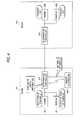
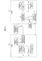
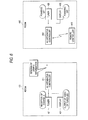
- Figs. 4 to 7 are views for explaining an example of the operation of the AV apparatus network system according to the embodiment of the invention.
- each of AV apparatus controllers 411 and 412 shown in Figs. 4 to 7 is the same as the AV apparatus controller 1 shown in Fig. 1.
- a remote controller 440 in the user A's hand is communicating with an AV apparatus controller 411 belonging to the unit system installed in this room 401 by wireless in one-to-one correspondence (see Fig. 4).
- the remote controller 440 sets the AV apparatus controller 411 to be used by the user A.
- Various kinds of operation information including setting information inputted by the user A through the remote controller 440 are recorded as user information in the information record portion 13 shown in Fig. 2 (see Fig. 4).
- the user A can move from the room 401 to the room 402 while carrying the remote controller 440.
- the remote controller 440 also moves from the room 401 to the room 402. With the movement of the remote controller 440, the AV apparatus controller to be connected to the remote controller 440 by wireless is switched from the AV apparatus controller 411 in the room 401 to the AV apparatus controller 412 in the room 402 (see Fig. 5).
- the remote controller 440 notifies the AV apparatus controller 412 that the user A will use the unit system installed in the room 402.
- the AV apparatus controller 412 Upon reception of this notification, the AV apparatus controller 412 likewise notifies all AV apparatus controllers belonging to the other unit systems on the network that the user Awill use the unit system installed in the room 402 (see Fig. 5).
- the previous AV apparatus controller which has been connected to the remote controller 440 by wireless in one-to-one correspondence until now i.e., the AV apparatus controller 411 belonging to the unit system installed in the room 401 which has been used by the user A until now in this example
- the AV apparatus controller 412 makes operation (including setting) on AV apparatuses belonging to the unit system including the AV apparatus controller 412 as sufficiently as possible on the basis of the user A's operation history information given from the AV apparatus controller 411.
- a tuner 422 and a display 432 belonging to the unit system installed in the room 402 are set so that the tuner 422 and the display 432 are powered on, the channel received by the tuner 422 is tuned to broadcast channel X and the video received by the tuner 422 is supplied to the display 432 (see Fig. 7).
- the AV apparatus controller i.e., the AV apparatus controller 411 in this example
- the AV apparatus controller 411 powers off the tuner 421 and the display 431 in this example (see Fig. 7).
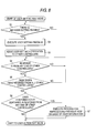
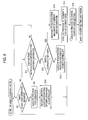
- Figs. 8 and 9 are flow charts showing the operation of the AV apparatus network system according to the embodiment of the invention.
- Steps S1 to S7 in Fig. 8 show an operation in an AV apparatus controller to be newly used by the user (e.g., the AV apparatus controller 412 shown in Figs. 4 and 5), that is, an operation in the "user setting wait mode”.
- Steps S8 to S16 in Fig. 9 show an operation in an AV apparatus controller which is not the target to be used by the user (e.g., the AV apparatus controller 411 shown in Figs. 4 and 5), that is, an operation in the "user action wait mode".
- step S1 a judgment is made as to whether a request to set a new user is received by the AV apparatus controller (e.g., the AV apparatus controller 412 shown in Figs. 4 and 5).
- the AV apparatus controller e.g., the AV apparatus controller 412 shown in Figs. 4 and 5.
- the remote controller when the AV apparatus controller to be connected by wireless (e.g., the remote controller 440 shown in Figs. 4 and 5) is switched to another AV apparatus with the movement of the user, the remote controller sends the new user setting request to the AV apparatus switched and connected by wireless.
- the remote controller sends the new user setting request to the AV apparatus switched and connected by wireless.
- step S2 When the new user setting request is received from the remote controller, the situation of the procedure goes to step S2. When there is no new user setting request received, the situation of the procedure goes back to the step S1. Next, in step S2, the user issuing the request is set (registered) in the AV apparatus controller.
- step S3 the AV apparatus controller notifies AV apparatus controllers belonging to the other unit systems that the new user has been set.
- step S4 a judgment is made as to whether or not a response to the notification is received from any one of the other AV apparatus controllers (e.g., the AV apparatus controller 411 shown in Figs. 4 and 5). When the response is received, the situation of the procedure goes to step S5. When there is no response received, the situation of the procedure goes back to the step S4.
- step S5 a judgment is made as to whether or not responses to the notification have been already received from all the other AV apparatus controllers.
- the situation of the procedure goes to step 56.
- reception of the responses from all the other AV apparatus controllers is not completed, the situation of the procedure goes back to the step S4.
- step S6 a judgment is made as to whether or not the responses received from the other AV apparatus controllers contain operation history information indicating the history of the operations of the other AV apparatus controller made by the user issuing the request.
- operation history information indicating the history of the operations of the other AV apparatus controller made by the user issuing the request.
- the situation of the procedure goes to step S7.
- the mode shifts to the "user action wait mode" shown in steps S8 to S16.
- step S7 the user's operations of the other AV apparatus controller is reproduced on an AV apparatus connected to the AV apparatus controller receiving the new user setting request, on the basis of the history information.
- step S8 a judgment is made as to whether or not the AV apparatus controller (e.g., the AV apparatus controller 411 shown in Figs. 4 and 5) receives an operation request from the user.
- the AV apparatus controller e.g., the AV apparatus controller 411 shown in Figs. 4 and 5
- step S9 a judgment is made as to whether or not the AV apparatus controller (e.g., the AV apparatus controller 411 shown in Figs. 4 and 5) receives an operation request from the user.
- the situation of the procedure goes to step S9.
- the situation of the procedure goes to step S11.
- step 39 aprocess (an operation including setting of AV apparatuses) corresponding to the operation requested by the user is executed.
- this operation is recorded as history information in the information record portion 13. Then, the situation of the procedure goes back to the step S8 to wait for the next operation request.
- step S11 a judgment is made as to whether or not a notification of the new user setting is received from any other AV apparatus controller (e.g., the AV apparatus controller 412 shown in Figs. 4 and 5).
- the situation of the procedure goes to step S12.
- the situation of the procedure goes back to the step S8.
- step S12 a judgment is made as to whether or not the user designated by the received notification of the new user setting is identical to the currently set user (i.e., the user issuing the operation request) .
- the situation of the procedure goes to step S13.
- the situation of the procedure goes to step S14.
- step S13 the user designated by the notification of the new user setting is registered as a user of the other AV apparatus controller issuing the notification.
- step S14 operation history information indicating the history of operations recorded in the information record portion 13 of the AV apparatus controller until now is sent to the other AV apparatus controller transmitting the notification of the new user setting.
- step S15 a process for terminating the current user's viewing is executed (e.g., the tuner 421 and the display 431 shown in Fig. 7 are powered off).
- step S16 a process for canceling the current user setting is executed. Then, the mode shifts to the "user setting wait mode" shown in steps S1 to S7.
- each of the unit systems A, B and C has one AV apparatus controller
- the invention can be generally applied to the case where one AV apparatus controller corresponds to a plurality of unit systems.
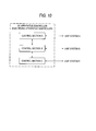
- Fig. 10 shows an example of the AV apparatus controller in the latter case.
- the AV apparatus controller has a control section A for controlling a unit system A, a control section B for controlling a unit system B, and a control section C for controlling a unit system C.
- the configuration of each of the control sections A, B and C is the same as that of the control section 10 shown in Fig. 2.
- control sections A, B and C are connected to the unit systems by networks so that the control sections A, B and C can two-way communicate with the unit systems respectively.
- the control sections A, B and C are connected to one another by a network in the AV apparatus controller so that the control sections A, B and C can two-way communicate with one another.
- each of the all unit systems is formed to have a transmission/reception unit (communication unit) to/from a remote controller.
- the remote controller may have some user identification unit (such as an entrance/exit sensor, a push button, a wireless tag, a portable telephone, etc.) so that the user identification unit can be operated.
- some user identification unit such as an entrance/exit sensor, a push button, a wireless tag, a portable telephone, etc.
- control such as adjustment of air-conditioning (air conditioner) and brightness (illuminator) in the room can be added easily in the process.
- an electronic apparatus network system including a plurality of unit systems which are connected to one another by a network so that the unit systems can two-way communicate with one another, each of the unit systems including at least one electronic apparatus, and an electronic apparatus controller having a control section for networking the at least one electronic apparatus, wherein the electronic apparatus network system further includes a unit for handing over settings in accordance with location movement of a user in such a manner that settings in use state of at least one electronic apparatus included in one unit system used by the user before the movement of the user are handed over to at least one electronic apparatus included in another unit system newly used by the user after the movement of the user.
- the operation required for terminating (e.g., powering off) the previously used electronic apparatuses with the location movement of the user can be dispensed with while the operation for starting (e.g., powering on) the newly used electronic apparatuses and the operation for re-setting the newly used electronic apparatuses by the same procedure as applied to the previously used electronic apparatuses before the movement can be dispensed with.
- the electronic apparatus network system further includes: a user setting command unit for giving a user setting command to a newly selected electronic apparatus controller to set the user as a new user when the electronic apparatus controller is newly selected to control a unit system placed at a location after the movement of the user, in accordance with the location movement of the user; and a user setting unit for setting the user as a new user by the newly selected electronic apparatus controller which has received the user setting command.
- the electronic apparatus network system further includes: a history information sending unit for sending history information indicating a history of user operations to any other control section when a notification of the user setting is received from the any other control section with the location movement of the user and the already set user is identical to a user designated by the notification of the user setting; and an operation restoration unit for operating at least one electronic apparatus connected to the newly selected electronic apparatus controller on the basis of history information indicating a history of user operations when a response to the notification is received and the history information is contained in the response. Accordingly, the operations which have been made on the previously used electronic apparatus controller by the user before the switching can be reproduced on electronic apparatuses connected to the newly used electronic apparatus controller after the switching on the basis of the history information indicating a history of user operations.
- the electronic apparatus network system further includes an operation command transmission unit for transmitting the operation command inputted by the user to a nearest electronic apparatus controller. Accordingly, because the operation command transmission unit transmits the operation command inputted by the user to the nearest electronic apparatus controller, the location after the movement of the user can be specified surely.
- the operation command transmission unit has a user identification unit constituted by an entrance/exit sensor, a push button, a wireless tag or a portable telephone. Accordingly, there can be achieved an electronic apparatus network system in which the user can be identified easily and surely.
- the operation command transmission unit has a two-way communication unit, and a display unit for displaying the operation command/data inputted by the user and information transmitted from the nearest electronic apparatus controller. Accordingly, there can be achieved an electronic apparatus network system in which the user's input operation transmitted by the operation command transmission unit can be made surely while information about the states of the electronic apparatuses to be operated by the user can be grasped.
- one electronic apparatus controller corresponds to a plurality of unit systems; and each of the plurality of unit systems has a communication unit which can communicate with the operation command transmission unit. Accordingly, there can be achieved an electronic apparatus network system in which a large installation place is not required as well as the cost can be saved.
- an electronic apparatus controller having a control section connected to at least one electronic apparatus and belonging to each of a plurality of unit systems which are connected to one another by a network so that the unit systems can two-way communicate with one another
- the electronic apparatus controller including: an operation unit for operating at least one electronic apparatus connected to the electronic apparatus controller when an operation command inputted by a user is received; a history information sending unit for sending history information indicating a history of user operations to any other control section when a notification of user setting is received from the any other control section with location movement of the user and the already set user is identical to a user designated by the notification of the user setting; a user setting unit for setting the user as a new user when a user setting command to set the user as a new user is received with the location movement of the user; and an operation restoration unit for operating at least one electronic apparatus connected to the electronic apparatus controller on the basis of the history information indicating a history of user operations when a response to the notification is received and the history information is contained in the response.
- an electronic apparatus controller having a control section necessary for forming an electronic apparatus network system in which the operation required for terminating (e.g., powering off) the previously used electronic apparatuses with the location movement of the user can be dispensed with while the operation for starting (e.g., powering on) the newly used electronic apparatuses and the operation for re-setting the newly used electronic apparatuses by the same procedure as applied to the previously used electronic apparatuses before the movement can be dispensed with.
- an electronic apparatus control method for executing a process of an electronic apparatus controller having a control section which is connected to at least one electronic apparatus and which belongs to each of a plurality of unit systems, the unit systems being connected to one another by a network so that the unit systems can two-way communicate with one another, the method including: the operating step of operating at least one electronic apparatus connected to the electronic apparatus controller when an operation command inputted by a user is received; the history information sending step of sending history information indicating a history of user operations to any other control section when a notification of user setting is received from the any other control section with location movement of the user and the already set user is identical to a user designated by the notification of the user setting; the post-process step of executing a process for canceling the already set user's viewing as a post-process after sending of the history information; the user setting step of setting the user as a new user when a user setting command to set the user as a new user is received with the location movement of the user; the user setting notifying step of notifying
- an electronic apparatus control method for making an electronic apparatus network system execute necessary control in which the operation required for terminating (e.g., powering off) the previously used electronic apparatuses with the location movement of the user can be dispensed with while the operation for starting (e.g., powering on) the newly used electronic apparatuses and the operation for re-setting the newly used electronic apparatuses by the same procedure as applied to the previously used electronic apparatuses before the movement can be dispensed with.
Landscapes
- Engineering & Computer Science (AREA)
- Signal Processing (AREA)
- Computer Networks & Wireless Communication (AREA)
- Multimedia (AREA)
- Automation & Control Theory (AREA)
- Human Computer Interaction (AREA)
- Physics & Mathematics (AREA)
- General Physics & Mathematics (AREA)
- Computer Security & Cryptography (AREA)
- Selective Calling Equipment (AREA)
- Details Of Television Systems (AREA)
Applications Claiming Priority (2)
| Application Number | Priority Date | Filing Date | Title |
|---|---|---|---|
| JP2002147035 | 2002-05-22 | ||
| JP2002147035A JP2003338947A (ja) | 2002-05-22 | 2002-05-22 | 電子機器ネットワークシステム、電子機器制御装置、及び電子機器制御方法 |
Publications (2)
| Publication Number | Publication Date |
|---|---|
| EP1365373A2 true EP1365373A2 (de) | 2003-11-26 |
| EP1365373A3 EP1365373A3 (de) | 2004-12-08 |
Family
ID=29397842
Family Applications (1)
| Application Number | Title | Priority Date | Filing Date |
|---|---|---|---|
| EP20030253204 Withdrawn EP1365373A3 (de) | 2002-05-22 | 2003-05-22 | Verbindungssystem für elektronische Geräte, Steuergerät für elektronische Geräte und Steuerungsverfahren für elektronische Geräte |
Country Status (3)
| Country | Link |
|---|---|
| US (1) | US20030218613A1 (de) |
| EP (1) | EP1365373A3 (de) |
| JP (1) | JP2003338947A (de) |
Cited By (3)
| Publication number | Priority date | Publication date | Assignee | Title |
|---|---|---|---|---|
| WO2007034431A3 (en) * | 2005-09-26 | 2008-12-31 | Koninkl Philips Electronics Nv | Portable control device for controlling playback streams in distributed system |
| EP2160023A1 (de) * | 2008-09-01 | 2010-03-03 | Samsung Electronics Co., Ltd. | Rundfunkempfangsvorrichtung, die mit einer externen Vorrichtung kommunizieren kann, und Verfahren zur Verwendung von Inhalten |
| EP1835740A4 (de) * | 2004-12-09 | 2010-11-24 | Panasonic Corp | System zur inhaltdarsztellung |
Families Citing this family (10)
| Publication number | Priority date | Publication date | Assignee | Title |
|---|---|---|---|---|
| CA2486671C (en) * | 2002-05-31 | 2011-11-15 | Onkyo Corporation | Network type content reproducing system |
| EP1653736A1 (de) * | 2003-07-25 | 2006-05-03 | Matsushita Electric Industrial Co., Ltd. | Energiespar-steuereinrichtung und -verfahren |
| JP4596236B2 (ja) * | 2004-04-07 | 2010-12-08 | ソニー株式会社 | 制御システム、制御装置および方法、プログラム、並びに記録媒体 |
| US8214447B2 (en) | 2004-06-08 | 2012-07-03 | Bose Corporation | Managing an audio network |
| JP4785489B2 (ja) * | 2005-10-14 | 2011-10-05 | キヤノン株式会社 | 情報処理装置及びその制御方法 |
| TWM376073U (en) * | 2009-07-16 | 2010-03-11 | Wan-Tian Chen | Remote control for wireless electric appliances |
| US9786159B2 (en) | 2010-07-23 | 2017-10-10 | Tivo Solutions Inc. | Multi-function remote control device |
| US8468568B2 (en) | 2010-10-14 | 2013-06-18 | Comcast Cable Communications, LLC. | Transmission of video signals |
| JP6080493B2 (ja) * | 2012-10-26 | 2017-02-15 | 大和ハウス工業株式会社 | エネルギー消費機器制御システム、エネルギー消費機器制御方法及びエネルギー消費機器制御装置 |
| CN104170400B (zh) * | 2012-12-28 | 2018-05-25 | 松下电器(美国)知识产权公司 | 控制方法 |
Family Cites Families (7)
| Publication number | Priority date | Publication date | Assignee | Title |
|---|---|---|---|---|
| US5910799A (en) * | 1996-04-09 | 1999-06-08 | International Business Machines Corporation | Location motion sensitive user interface |
| DK0932398T3 (da) * | 1996-06-28 | 2006-09-25 | Ortho Mcneil Pharm Inc | Anvendelse af topiramat eller derivater deraf til fremstilling af et lægemiddel til behandling af maniodepressive bipolære forstyrrelser |
| JP3658896B2 (ja) * | 1996-11-26 | 2005-06-08 | ソニー株式会社 | 情報信号伝送システム、再生装置及び表示装置 |
| JP2002525942A (ja) * | 1998-09-17 | 2002-08-13 | コーニンクレッカ フィリップス エレクトロニクス エヌ ヴィ | 位置依存インタフェースを具えるリモートコントロール装置 |
| US6813775B1 (en) * | 1999-03-29 | 2004-11-02 | The Directv Group, Inc. | Method and apparatus for sharing viewing preferences |
| JP2000307594A (ja) * | 1999-04-21 | 2000-11-02 | Nec Corp | Av機器の機能の最適処理分散システム |
| WO2002065771A1 (en) * | 2001-02-09 | 2002-08-22 | Quadriga Technology Limited | System for and method of distributing television, video and other signals |
-
2002
- 2002-05-22 JP JP2002147035A patent/JP2003338947A/ja active Pending
-
2003
- 2003-05-20 US US10/441,183 patent/US20030218613A1/en not_active Abandoned
- 2003-05-22 EP EP20030253204 patent/EP1365373A3/de not_active Withdrawn
Cited By (4)
| Publication number | Priority date | Publication date | Assignee | Title |
|---|---|---|---|---|
| EP1835740A4 (de) * | 2004-12-09 | 2010-11-24 | Panasonic Corp | System zur inhaltdarsztellung |
| WO2007034431A3 (en) * | 2005-09-26 | 2008-12-31 | Koninkl Philips Electronics Nv | Portable control device for controlling playback streams in distributed system |
| US9917703B2 (en) | 2005-09-26 | 2018-03-13 | Koninklijke Philips N.V. | Portable control device for controlling playback streams in distributed system |
| EP2160023A1 (de) * | 2008-09-01 | 2010-03-03 | Samsung Electronics Co., Ltd. | Rundfunkempfangsvorrichtung, die mit einer externen Vorrichtung kommunizieren kann, und Verfahren zur Verwendung von Inhalten |
Also Published As
| Publication number | Publication date |
|---|---|
| US20030218613A1 (en) | 2003-11-27 |
| JP2003338947A (ja) | 2003-11-28 |
| EP1365373A3 (de) | 2004-12-08 |
Similar Documents
| Publication | Publication Date | Title |
|---|---|---|
| EP1365373A2 (de) | Verbindungssystem für elektronische Geräte, Steuergerät für elektronische Geräte und Steuerungsverfahren für elektronische Geräte | |
| US7793328B2 (en) | Gateway power synchronization | |
| JPH07162843A (ja) | 遠隔制御装置及び画像入力装置 | |
| JP2001024685A5 (ja) | 制御システム及び制御装置 | |
| CN1157946C (zh) | 由设备和外部设备构成的系统 | |
| CN104345704A (zh) | 一种酒店客房无线智能中控系统及其控制方法 | |
| EP1411671A1 (de) | Einrichtungsgruppierungssystem, empfangsvorrichtung, management-vorrichtung, einrichtungsgruppierungsverfahren, programm und medium | |
| EP1381187A1 (de) | Fernbedienung und Statusanzeige einer Audio-/Video-Funktionseinheit in einem drahtlosen LAN | |
| JP4339312B2 (ja) | 無線映像伝送システム及び方法 | |
| US20050212687A1 (en) | Control system, controlling device, control method, and program | |
| WO2009020133A1 (en) | Image processing apparatus and image processing system | |
| JP2003032573A (ja) | 表示システム、表示装置及び制御装置 | |
| EP1747507A1 (de) | Mehrfach-display-system und display-vorrichtung | |
| GB2256515A (en) | Interactive remote control | |
| JP4298145B2 (ja) | カメラ制御方法、携帯電話、及びカメラ制御サービスサーバ | |
| KR20060132099A (ko) | 객실 시설물 제어방법 및 영상표시기기, 그에 따른 관리시스템 | |
| EP1987294A2 (de) | Zentrales steuersystem und betriebsverfahren dafür | |
| JP2005051376A (ja) | 家電機器制御装置及び制御プログラム | |
| JPH0896183A (ja) | 遠隔監視・制御システム | |
| JP2003324780A (ja) | 家庭内電気機器制御方法、家庭内電気機器制御システムおよび映像機器 | |
| JP2967695B2 (ja) | 多室型空気調和機 | |
| TW589587B (en) | Automatic monitoring system with dual-frequency | |
| JP3196386B2 (ja) | リモートコントローラによる仕様設定装置 | |
| JP2005311549A (ja) | ホームサーバシステムおよびそれに用いるリモートコントローラ | |
| JP2002345053A (ja) | 遠隔制御システム |
Legal Events
| Date | Code | Title | Description |
|---|---|---|---|
| PUAI | Public reference made under article 153(3) epc to a published international application that has entered the european phase |
Free format text: ORIGINAL CODE: 0009012 |
|
| AK | Designated contracting states |
Kind code of ref document: A2 Designated state(s): AT BE BG CH CY CZ DE DK EE ES FI FR GB GR HU IE IT LI LU MC NL PT RO SE SI SK TR |
|
| AX | Request for extension of the european patent |
Extension state: AL LT LV MK |
|
| PUAL | Search report despatched |
Free format text: ORIGINAL CODE: 0009013 |
|
| AK | Designated contracting states |
Kind code of ref document: A3 Designated state(s): AT BE BG CH CY CZ DE DK EE ES FI FR GB GR HU IE IT LI LU MC NL PT RO SE SI SK TR |
|
| AX | Request for extension of the european patent |
Extension state: AL LT LV MK |
|
| 17P | Request for examination filed |
Effective date: 20050527 |
|
| AKX | Designation fees paid |
Designated state(s): DE FR GB |
|
| 17Q | First examination report despatched |
Effective date: 20071113 |
|
| STAA | Information on the status of an ep patent application or granted ep patent |
Free format text: STATUS: THE APPLICATION IS DEEMED TO BE WITHDRAWN |
|
| 18D | Application deemed to be withdrawn |
Effective date: 20080324 |