EP1365543A2 - Méthode et dispositif pour la transmission d'informations et la détection d'erreurs dans un réseau en anneau - Google Patents
Méthode et dispositif pour la transmission d'informations et la détection d'erreurs dans un réseau en anneau Download PDFInfo
- Publication number
- EP1365543A2 EP1365543A2 EP03004425A EP03004425A EP1365543A2 EP 1365543 A2 EP1365543 A2 EP 1365543A2 EP 03004425 A EP03004425 A EP 03004425A EP 03004425 A EP03004425 A EP 03004425A EP 1365543 A2 EP1365543 A2 EP 1365543A2
- Authority
- EP
- European Patent Office
- Prior art keywords
- information
- frame
- participant
- transmitted
- transmission path
- Prior art date
- Legal status (The legal status is an assumption and is not a legal conclusion. Google has not performed a legal analysis and makes no representation as to the accuracy of the status listed.)
- Granted
Links
Images


Classifications
-
- H—ELECTRICITY
- H04—ELECTRIC COMMUNICATION TECHNIQUE
- H04L—TRANSMISSION OF DIGITAL INFORMATION, e.g. TELEGRAPHIC COMMUNICATION
- H04L43/00—Arrangements for monitoring or testing data switching networks
- H04L43/50—Testing arrangements
-
- H—ELECTRICITY
- H04—ELECTRIC COMMUNICATION TECHNIQUE
- H04L—TRANSMISSION OF DIGITAL INFORMATION, e.g. TELEGRAPHIC COMMUNICATION
- H04L12/00—Data switching networks
- H04L12/28—Data switching networks characterised by path configuration, e.g. LAN [Local Area Networks] or WAN [Wide Area Networks]
- H04L12/42—Loop networks
- H04L12/437—Ring fault isolation or reconfiguration
-
- H—ELECTRICITY
- H04—ELECTRIC COMMUNICATION TECHNIQUE
- H04L—TRANSMISSION OF DIGITAL INFORMATION, e.g. TELEGRAPHIC COMMUNICATION
- H04L12/00—Data switching networks
- H04L12/28—Data switching networks characterised by path configuration, e.g. LAN [Local Area Networks] or WAN [Wide Area Networks]
- H04L12/42—Loop networks
- H04L12/427—Loop networks with decentralised control
- H04L12/43—Loop networks with decentralised control with synchronous transmission, e.g. time division multiplex [TDM], slotted rings
Definitions
- the invention relates to a method and an apparatus for the transmission of Information in a network and a corresponding network with at least three participants, the information in at least a first frame given length and structure is transferred according to the generic terms of independent claims.
- Such distributed security-relevant systems are, for example, from the Vehicle area known as X-by-wire systems.
- the most important task is that to ensure functional safety of such systems. This is in the article "X-by-Wire - The safe alternative ", from the Auto and Electronics 2/2000 on pages 73 to 75 described.
- a method and a device for transmitting information in a network with at least three participants the information is transmitted in at least a first frame of predetermined length and structure and the first frame in a ring on the first transmission path to the respective the next, second participant is transmitted with a predetermined transmission direction, the information advantageously being the same in a second frame Length and structure of how the first frame is transmitted, with the second frame on a second transmission path to a third party after next , the second transmission path and thus the second frame the second Participant skips and depending on at least one criterion, i.e. information, Length or structure an assessment is made.
- the second frame can be identical to the first one, but the transmission path is different.
- a ring-shaped structure is therefore proposed, with or for each participant Network nodes at least two inputs, i.e. from the predecessor and its predecessor, are provided.
- Information is then automatically recognized (e.g. by comparison the information, in particular the data content, the checking of the structure and / or the Length of the frame), whether the transmitted information, especially the data of are valid at least one predecessor or whether a decision must be made on errors.
- you can then special measures such as switching to another input or the blocking of the faulty input can be initiated.
- the can Number of inputs to be considered can be specified, in particular be programmable.
- the frames expediently each contain first information areas according to the number of participants in the network, with each participant the first information area is clearly assigned. I.e. every participant will an area or an area within a frame, i.e. an information frame assigned to a specific position, which in a subsequent embodiment Comparison of information between two frames made easier.
- the information is expediently at least in data information and Validity information differentiated, with existing validity information and missing or implausible data information when evaluating for errors is decided.
- At least one of the details, ie information, length or Structure in the first and second frames at least partially for evaluation compared with each other and it is decided on errors if these in the compared parts do not match. It is appropriate to such parts compare, which were also transmitted over all considered transmission paths.
- the information is encoded in bifrequency transmitted so that regardless of the content of the information signals on the Network are transmitted and in the absence of signals or if they do not match the signals with the code are decided on errors in at least one transmission path becomes.
- At least one suitable one when deciding on errors Measure initiated.
- This can be, for example, an information input of a Switch off the participant from a transmission path that was identified as faulty or block, so that the information and the frame only about the further Transmission path are transmitted. Likewise, the over the as faulty recognized transmission path incoming information or the corresponding frame also be rejected as faulty in the participant himself.
- the detection of an error that is to say Evaluation, a functional test carried out by at least one participant, wherein at least one participant is specified as defective by at least one of the Information, i.e. information, structure or length at least partially changed and is transmitted by the subscriber specified as incorrect. On the expected Errors can then be checked to see if the appropriate action is being taken.
- a subscriber who has a master function exercises, i.e. controls the transmission of information in the network by this generates at least one frame, usually by specifying Information areas or time slots based on your own clock. Now becomes a If errors in the master are decided or detected, the next one can advantageously open the master following participants take over the master function, if this either has its own base clock (e.g. through a connected quartz oscillator) or such from an application connected to the output interface can take over. If the master fails, there is either no or only a reduced one Network activity as long as no new master exists.
- Each frame expediently contains identification information relating to the frame clearly identifies, with redundant frames that have different Transmission paths are transmitted that have the same identifier.
- the information also contains at least control information and data information, the control information being used to control the transmission of the frames.
- that control information can also be transmitted can advantageously be a additional reset line or additional control lines are omitted as well on the synchronization of the internal counters, which serve as time bases for the participants.
- the information contains at least status information, which describes the network status, the status information either the corresponds to the current network status or is related to the corresponding frame.
- This status information can then expediently be at least one Correspond to or contain connection information which contains the status of a concrete predefinable transmission path, in particular the transmission path, via which the corresponding frame was transmitted, represents or contains.
- At least four participants have a third frame with the same length and structure as the first two frames transmitted, the fourth participant the first frame of the third participant, the second frame from the second participant and the third participant from the first Participant and in the second frame the third participant and in the third frame the second and third participants are skipped.
- FIG. 1 shows a network according to the invention with subscribers 101 to 104 Input interfaces 105 to 108 are shown, each with three inputs X, Y and Z. Output interfaces 109 to 112 are also shown in each subscriber. there corresponds to each input X, Y, Z of the input interfaces 105 to 108 Transmission path, which was therefore not designated separately, but the same Name like the respective input interface, e.g. 105X or 107Z wearing.
- the information is transmitted via the output interfaces 109 to 112, different configuration options are available.
- the interface 109 is designed to have three output interfaces within the scope of the 106X, 107Y and 108Z transmission paths, i. H. that a division or a Definition of three transmission frames already in the participant, especially in Interface 109 happens. It can also, for example, for longer Transmission links, a signal or level adjustment with respect to the frames that over these longer transmission paths are transmitted.
- interface 110 in connection with branching element 113 shows a further possibility of Configuration. The information is transmitted in the frame from 110 to 113 and the frame is divided or doubled or tripled in the element 113 with respect to the transmission paths 107X, 108Y and 105 Z.
- this branch element is formed only as a simple line coupling 114. I.e. the information is in transfer the frame from interface 11 and there is only a branching of the Signals via element 114 on transmission path 105Y and again via element 117 on transmission route 106Z. I.e. in the simplest case, the signals are simply on the divided into three transmission paths. A first frame is thus created via inputs X, a second frame via inputs Y and a third frame via inputs Z transfer.
- 115 and 116 are generally also simple Branch elements are shown, the possibilities shown Output interfaces can be used consistently or in any combination can.
- FIG. 2 now shows a single subscriber 200 of such a network with three Transmission paths 201X, 201Y and 200Z, with 201 again the Input interface is shown. With 209 and 210 are again branch elements, such as previously described, shown. An element 202 is shown as the output interface. The transmission paths end in three inputs X, Y, Z, each with a receiver 205, 206 and 207 is assigned. The information received or received Frames are then fed to a selection device 203, which on the one hand selectively with the frame or the corresponding information to the data storage Data evaluation or evaluation 204 forwards. For easier illustration is as Memory and evaluation device shown only one block 204. But this is also the case possible separately.
- evaluation device 204 directs the corresponding one Information or a frame to the output interface 202, and to Others a result of the evaluation of an element 208, which is equally a separate component or software or program part, just an application, represents.
- element 208 is a processor unit or microcomputer unit for processing shown, with 211 a memory element.
- element 213 a internal time base from which a clock can be generated. If a participant has one Assigned master function, so this participant controls the transmission in the Network, a network clock can be specified based on this internal clock so that a framework for transmission with different information areas can be derived from this time clock and all other network participants their Can recover clock from the data signal.
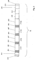
- Such a frame is shown in FIG. 3 and labeled R.
- Information areas 300 to 313 are shown. These information areas contain, for example, binary information in bit or byte form.
- Are Information areas are shown that can be clearly assigned to a participant. For subscribers 101 to 104, these are areas I 101 to I 104, the Order can be seen arbitrarily and as an example.
- R now contain information areas 302 to 305, in which Validity information, in particular subscriber status information, are stored can.
- These validity information areas show, for example, the type and validity the information, in particular the data in the following areas 306 to 309, whereby a validity area and a data area each define a subscriber assigned.
- an identification area 300 in which Identification information relating to the frame is stored, i. H. a frame is through the Identifier or identifier information 300, wherein in a special Embodiment same frame over different transmission paths are transmitted, contain the same identifiers; may differ that these can be assigned to each other, but at the same time the transmission path are assignable.
- Area 201 contains, for example, status information regarding the Network.
- block 310 contains a reserved area for Further information.
- Information is stored, for example, in the information area 311 regarding a consistency check of the frame, i.e. control bytes, for example with regard to a cyclic redundancy check or also to check the cycle and length of the Frames as well as the frame position monitoring.
- Control information stored i.e. control information that enables in particular to control the transmission of the information to the master.
- control information that enables in particular to control the transmission of the information to the master.
- block 313 for example, the information previously also mentioned in block 311 filed for length and structure check of the frame R, with block 314 as Example added a parity bit as a further checking and evaluation measure is.
- the frame structure just shown can only be seen as an example. According to the invention a different frame structure is also possible depending on the application according to the invention and applicable. The same applies to the information transmitted in the frame.
- the information i.e. the information, in particular the data or serial data information in the network in a frame or with predetermined, in particular fixed number of binary information, in particular bytes transfer.
- Each participant in the network receives in particular according to his Position clearly an information area, in particular composed of Area of validity and data area assigned.
- a participant, especially the Participant 101 acts as a master, that is to say exercises the master function, i.e. controls the master entire information transfer.
- the internal clock of the master System clock derived and this master generates based on its internal Clock the system clock and thus the framework for information transfer.
- the transmission of the information is possible in parallel because every participant in it Design a fixed position in the framework for the transmission of his Data information or status or validity information 302 to 305 is assigned.
- the evaluation itself i.e. the voting, can now be carried out in participant 103 by the controller, (comparable 212) in the data evaluation module (comparable 204).
- Different errors can now be identified.
- One group of mistakes can be uncovered by examining a framework by doing consistency checks within the frame and contiguous or interdependent within it Data or information are carried out.
- a second group of bugs can be recognized, for example, by the fact that the first and the second frame, ie how received in the example about 107X and 107Y or the information contained therein are at least partially compared with each other and checked for agreement become.
- the details to be checked relate on the one hand to the transported information and / or the length of the frame or the information contained and / or the structure of the frame.
- any error can be identified by comparison with Exception in the information area 1102 because the first frame in this area may have changed data since the subscriber 102 intervenes in this area may. All other information areas, that is, all those in which subscriber 102 none Changes to the first frame must be made via 107X and of the second frame over 107Y. A deviation here shows an error on.
- the frames R themselves must be the first and second frames with regard to their Length as well as their structure, i.e. the information areas 300 to 313 have the same structure and deviations in a comparison of both frames also result to decide on mistakes. This also includes clock errors, since these directly affect either the structure and / or the length of the frame.
- identification information stored in the frame has identifiable identification information that can be assigned.
- the further 2 bits serve, for example, to distinguish the first frame via transmission path 106X or 107X from the second frame via transmission path 107Y.
- the frames can be clearly assigned to one another, but the transmission paths can still be determined, which means that the correct transmission path or the corresponding input can be blocked in the event of an error.
- This identifier thus enables synchronization to an event to be assessed, and the position of the subscriber in the network can also be used to establish a clear time reference, in particular to the master, with an unambiguous assignment. Errors can also be decided by checking for consistency within the framework.
- test information for example the control bytes of a cyclic redundancy check with regard to information parts of the frame.
- a parity check for example by means of a parity bit, as shown in block 314.
- a clock deviation in the frame or a frame position deviation can also be detected by appropriate monitoring.
- Internal node errors for example that the data information in block 307 does not correspond to the type and validity information in block 303, also lead to a decision for errors. If, for example, validity information in block 303 indicates that data is contained in block 307 but this data is missing, a decision is made about errors.
- Bifrequency coding or biphase coding means that each data bit is assigned a time interval which begins with a transition, in particular between two levels, and ends with a transition between these two levels. If there is another transition within this time interval, the corresponding data bit is to be interpreted as 1 within the scope of the coding, otherwise as 0.
- clock information and the information itself that is to say in particular data information, can be coded equally. If the information is transmitted coded in such a form, there is constant or continuous activity on the transmission paths or on the network regardless of the information itself, i.e. the information content. If the absence of this bifrequency coding is then recognized on at least one transmission path, then in In this case, errors are also decided.
- test measures as part of the assessment for the decision on errors can be used individually or in any combination, which also additional redundancy can be achieved.
- These evaluation mechanisms create furthermore the possibility of defective transmission paths and participants very quickly recognize, in particular by the bifrequency coding and automatically corresponding Take measures to control the error.
- the voting or rating is carried out by means of an N-out-of-K evaluation, for example three Participants equal N and two inputs or transmission paths per participant equal K can depend on the choice of N and K with a certain number of errors be reacted to.
- a voter structure for a is created K-out-of-4 voting, especially 3-out-of-4 voting if two are admitted, for example Network errors.
- the two network errors result from a maximum of three inputs and therefore three Transmission paths are available and thus with two occurring Network errors either on the transmission paths or in participants nevertheless correct framework with appropriate information is available. Because through the Transmission paths participants are skipped and possibly the data If this subscriber is not up-to-date or is not correctly contained, it is according to the invention conceivable to make a correction and the appropriate framework to the send the relevant participant back to the appropriate correction of the Information. This can be simplified by status information in the frame, so that in the event of a correction, the status information correction or correction is recognized.
- Other statuses are, for example, initial for initialization, enter for data entry, Distribute for data distribution, master lost for serious master errors and loss of Master role of this participant, ready or finished, empty or empty, fault free, that is error-free transmission, error or error, data equal, i.e. equal data or data not equal, so unequal data, if this is already known from the start and test in In case of a test run. So not only the status of the Network itself can be recognized by any node, but also the current status of each subscriber if between network status and subscriber status is distinguished. So statuses for transmission paths, for participants or that entire network can be used, which at the same time the assessment ability or Valuation security and accuracy increased, for example, if "data not equal "takes this into account when comparing two pieces of information must become.
- control information for example to control the transmission by a master.
- the error "Master lost", the failure of the master is very high serious.
- This failure of the master can, for example, via the status information, in particular in connection with the data information.
- individual or all error mechanisms as described above, applicable.
- this subsequent master either has an independent clock, for example, from the application, or via its own clock to, in the case of necessary takeover of the master function to be able to drive the data, because how described, the master specifies the clock, especially in frames.
- frequency division or frequency multiplication e.g.
- PLL PLL
- a PLL is for any non-master network participant anyway (Slave) required if the clock does not have a separate Line is additionally transmitted, but can be recovered from the data In the event that the beat cannot be recovered, there is also one Parallel clock transmission from the master to all slaves or all other participants possible. This clock transmission must be similar to the data transmission, i.e. the Information transmission can be made using several parallel lines automatic replacement of failed clock lines.
- a test of the transmission paths or of the participants can also be carried out in that these are determined to be faulty, i.e. errors are explicitly incorporated.
- Such a Test can also be done periodically and cyclically by all participants in succession or tested according to certain specifications. So in this test the Information of a frame is stored, for example in a storage means, comparable to 211, then evaluated and possibly modified, as part of the test just sent incorrectly modified again. As a result, that also with the Test the next node or subscriber for example by two Receive frame delayed.
- the synchronization can be assessed Event, here the test event in particular through the identifier at the beginning of a Framework can be achieved, and also by the participant position a clear Time reference to the master can also be established as part of the test.
- the This test can be controlled by the master, for example through control information or control bytes in the frame, in particular through corresponding status information test.
- the adequate Response to the error i.e. the corresponding action taken, in the network checked.
- This measure can be recognized depending on the type of error be specified by the above-mentioned different evaluation criteria.
- a correction can be made, on the other hand faulty participants or transmission paths are either permanently excluded are blocked, switched off or data rejected or even tentatively be reintegrated, which is also due to transmitted status information can be represented. Blocking or switching off individual transmission paths or Participants can take place, for example, through the selection device 203 if this receives the specification from the evaluation device 204, for example No longer select inputs.
- the number is also via the selection device 203 of the inputs to be considered can be specified or programmed. So in the example any desired number of inputs up to a maximum of three inputs can be used, here, when using a redundancy principle, two or three inputs.
Landscapes
- Engineering & Computer Science (AREA)
- Computer Networks & Wireless Communication (AREA)
- Signal Processing (AREA)
- Small-Scale Networks (AREA)
- Detection And Prevention Of Errors In Transmission (AREA)
- Time-Division Multiplex Systems (AREA)
Applications Claiming Priority (2)
| Application Number | Priority Date | Filing Date | Title |
|---|---|---|---|
| DE10223007A DE10223007A1 (de) | 2002-05-22 | 2002-05-22 | Verfahren und Vorrichtung zur Übertragung von Informationen in einem Netzwerk sowie entsprechendes Netzwerk |
| DE10223007 | 2002-05-22 |
Publications (3)
| Publication Number | Publication Date |
|---|---|
| EP1365543A2 true EP1365543A2 (fr) | 2003-11-26 |
| EP1365543A3 EP1365543A3 (fr) | 2005-11-30 |
| EP1365543B1 EP1365543B1 (fr) | 2008-12-17 |
Family
ID=29285664
Family Applications (1)
| Application Number | Title | Priority Date | Filing Date |
|---|---|---|---|
| EP03004425A Expired - Lifetime EP1365543B1 (fr) | 2002-05-22 | 2003-02-27 | Méthode et dispositif pour la transmission d'informations et la détection d'erreurs dans un réseau en anneau |
Country Status (4)
| Country | Link |
|---|---|
| US (1) | US7890650B2 (fr) |
| EP (1) | EP1365543B1 (fr) |
| JP (1) | JP4426211B2 (fr) |
| DE (2) | DE10223007A1 (fr) |
Cited By (9)
| Publication number | Priority date | Publication date | Assignee | Title |
|---|---|---|---|---|
| WO2005053238A1 (fr) * | 2003-11-19 | 2005-06-09 | Honeywell International Inc. | Agregation en cliques dans des reseaux amrt |
| EP1638243A3 (fr) * | 2004-09-16 | 2006-07-19 | Robert Bosch Gmbh | Dispositif de traitement avec récupération d'horloge de sources différentes |
| US7372859B2 (en) | 2003-11-19 | 2008-05-13 | Honeywell International Inc. | Self-checking pair on a braided ring network |
| US7656881B2 (en) | 2006-12-13 | 2010-02-02 | Honeywell International Inc. | Methods for expedited start-up and clique aggregation using self-checking node pairs on a ring network |
| US7668084B2 (en) | 2006-09-29 | 2010-02-23 | Honeywell International Inc. | Systems and methods for fault-tolerant high integrity data propagation using a half-duplex braided ring network |
| US7778159B2 (en) | 2007-09-27 | 2010-08-17 | Honeywell International Inc. | High-integrity self-test in a network having a braided-ring topology |
| US7889683B2 (en) | 2006-11-03 | 2011-02-15 | Honeywell International Inc. | Non-destructive media access resolution for asynchronous traffic in a half-duplex braided-ring |
| US7912094B2 (en) | 2006-12-13 | 2011-03-22 | Honeywell International Inc. | Self-checking pair-based master/follower clock synchronization |
| US8817597B2 (en) | 2007-11-05 | 2014-08-26 | Honeywell International Inc. | Efficient triple modular redundancy on a braided ring |
Families Citing this family (5)
| Publication number | Priority date | Publication date | Assignee | Title |
|---|---|---|---|---|
| DE102004063105A1 (de) * | 2004-12-22 | 2006-07-13 | Robert Bosch Gmbh | Verfahren und Vorrichtung zur Übertragung von Informationen in einem Netzwerk |
| US7725403B2 (en) * | 2005-12-30 | 2010-05-25 | Ebay Inc. | Method and system to verify a transaction |
| DE102006059919A1 (de) | 2006-12-19 | 2008-07-03 | Robert Bosch Gmbh | Datenverarbeitungssystem für ein Kraftfahreug |
| US8199695B2 (en) * | 2007-04-10 | 2012-06-12 | International Business Machines Corporation | Clock signal synchronization among computers in a network |
| EP3651443A4 (fr) * | 2017-07-03 | 2020-07-15 | Denso Wave Incorporated | Dispositif de lecture d'informations optiques |
Family Cites Families (11)
| Publication number | Priority date | Publication date | Assignee | Title |
|---|---|---|---|---|
| GB2028062B (en) * | 1979-08-17 | 1982-07-21 | Standard Telephones Cables Ltd | Transmission system |
| US4354229A (en) * | 1980-03-10 | 1982-10-12 | International Business Machines Corporation | Loop initialization mechanism for a peer-to-peer communication system |
| JPH04360440A (ja) * | 1991-06-07 | 1992-12-14 | Hitachi Ltd | 伝送路障害検出方式 |
| US6065052A (en) * | 1996-07-01 | 2000-05-16 | Sun Microsystems, Inc. | System for maintaining strongly sequentially ordered packet flow in a ring network system with busy and failed nodes |
| DE19633744C2 (de) * | 1996-08-22 | 1999-07-22 | Baumueller Anlagen Systemtech | Ringgraph in einem elektrischen Antriebssystem |
| US5940367A (en) * | 1996-11-06 | 1999-08-17 | Pluris, Inc. | Fault-tolerant butterfly switch |
| US7046929B1 (en) * | 1999-08-24 | 2006-05-16 | Ciena Corporation | Fault detection and isolation in an optical network |
| US6785226B1 (en) * | 1999-09-01 | 2004-08-31 | Carriercomm, Inc. | System and method for data routing over a network |
| KR100385116B1 (ko) * | 2000-09-02 | 2003-05-22 | 국방과학연구소 | 다중 장애 허용망 구조를 이용한 패킷 처리 방법 |
| US7181534B2 (en) * | 2001-02-15 | 2007-02-20 | Ciena Corporation | Address resolution protocol to map internet protocol addresses to a node transport identifier |
| US6836514B2 (en) * | 2001-07-10 | 2004-12-28 | Motorola, Inc. | Method for the detection and recovery of errors in the frame overhead of digital video decoding systems |
-
2002
- 2002-05-22 DE DE10223007A patent/DE10223007A1/de not_active Withdrawn
-
2003
- 2003-02-27 EP EP03004425A patent/EP1365543B1/fr not_active Expired - Lifetime
- 2003-02-27 DE DE50310921T patent/DE50310921D1/de not_active Expired - Lifetime
- 2003-05-22 JP JP2003145100A patent/JP4426211B2/ja not_active Expired - Fee Related
- 2003-05-22 US US10/444,468 patent/US7890650B2/en not_active Expired - Fee Related
Cited By (15)
| Publication number | Priority date | Publication date | Assignee | Title |
|---|---|---|---|---|
| US7606179B2 (en) | 2003-11-19 | 2009-10-20 | Honeywell International, Inc. | High integrity data propagation in a braided ring |
| US7729297B2 (en) | 2003-11-19 | 2010-06-01 | Honeywell International Inc. | Neighbor node bus guardian scheme for a ring or mesh network |
| US7372859B2 (en) | 2003-11-19 | 2008-05-13 | Honeywell International Inc. | Self-checking pair on a braided ring network |
| US7502334B2 (en) | 2003-11-19 | 2009-03-10 | Honeywell International Inc. | Directional integrity enforcement in a bi-directional braided ring network |
| US7505470B2 (en) | 2003-11-19 | 2009-03-17 | Honeywell International Inc. | Clique aggregation in TDMA networks |
| US7649835B2 (en) | 2003-11-19 | 2010-01-19 | Honeywell International Inc. | Unsynchronous mode brother's keeper bus guardian for a ring networks |
| WO2005053238A1 (fr) * | 2003-11-19 | 2005-06-09 | Honeywell International Inc. | Agregation en cliques dans des reseaux amrt |
| EP1638243A3 (fr) * | 2004-09-16 | 2006-07-19 | Robert Bosch Gmbh | Dispositif de traitement avec récupération d'horloge de sources différentes |
| US7567630B2 (en) | 2004-09-16 | 2009-07-28 | Robert Bosch Gmbh | Data processing device including clock recovery from various sources |
| US7668084B2 (en) | 2006-09-29 | 2010-02-23 | Honeywell International Inc. | Systems and methods for fault-tolerant high integrity data propagation using a half-duplex braided ring network |
| US7889683B2 (en) | 2006-11-03 | 2011-02-15 | Honeywell International Inc. | Non-destructive media access resolution for asynchronous traffic in a half-duplex braided-ring |
| US7656881B2 (en) | 2006-12-13 | 2010-02-02 | Honeywell International Inc. | Methods for expedited start-up and clique aggregation using self-checking node pairs on a ring network |
| US7912094B2 (en) | 2006-12-13 | 2011-03-22 | Honeywell International Inc. | Self-checking pair-based master/follower clock synchronization |
| US7778159B2 (en) | 2007-09-27 | 2010-08-17 | Honeywell International Inc. | High-integrity self-test in a network having a braided-ring topology |
| US8817597B2 (en) | 2007-11-05 | 2014-08-26 | Honeywell International Inc. | Efficient triple modular redundancy on a braided ring |
Also Published As
| Publication number | Publication date |
|---|---|
| JP4426211B2 (ja) | 2010-03-03 |
| EP1365543A3 (fr) | 2005-11-30 |
| JP2004007691A (ja) | 2004-01-08 |
| US7890650B2 (en) | 2011-02-15 |
| DE10223007A1 (de) | 2003-12-11 |
| US20040073698A1 (en) | 2004-04-15 |
| EP1365543B1 (fr) | 2008-12-17 |
| DE50310921D1 (de) | 2009-01-29 |
Similar Documents
| Publication | Publication Date | Title |
|---|---|---|
| DE3750967T2 (de) | Steuerung von verteilten Taktimpulsen in einer verteilten Digital-Vermittlungsanlage. | |
| EP2274655B1 (fr) | Procédé, système et coupleur de bus pour l'échange de données entre un réseau de recouvrement et un réseau sous-jacent | |
| EP0964549B1 (fr) | Circuit de surveillance d'un réseau de transmission | |
| DE3127321C2 (fr) | ||
| EP1365543B1 (fr) | Méthode et dispositif pour la transmission d'informations et la détection d'erreurs dans un réseau en anneau | |
| DE3902243C2 (fr) | ||
| DE19934514C5 (de) | Verfahren zum Konfigurieren eines an einen Feldbus angeschlossenen Busteilnehmers | |
| EP1648116B1 (fr) | Procédé de transmission de données dans un système de communication | |
| WO2004084451A2 (fr) | Systeme de communication a communication redondante | |
| EP1495590B1 (fr) | Reseau comprenant un reseau de liaison et plusieurs noeuds de reseau couples audit reseau de liaison | |
| EP1509005A1 (fr) | Méthode et appareil pour la transmission de données par diffusion dans un réseau bus | |
| DE20220280U1 (de) | Vorrichtung zur Übertragung von Information in einem Netzwerk sowie entsprechendes Netzwerk | |
| DE10305415B4 (de) | Verfahren und Vorrichtung zum medienredundanten Betreiben eines Endgeräts in einem Netzwerk | |
| EP1955480A1 (fr) | Réseau ayant des propriétés de redondance, commutateur ethernet pour un réseau de ce type et procédé de configuration d un réseau de ce type | |
| DE112012000546B4 (de) | Übertragungsleitungs-Adressüberlappungs-Detektionssystem und Unterstation-Endgerät, das in dem System verwendet wird | |
| DE3636317C2 (fr) | ||
| DE10325263B4 (de) | Sicherstellung von maximalen Reaktionszeiten in komplexen oder verteilten sicheren und/oder nicht sicheren Systemen | |
| DE60034412T2 (de) | Kommunikationssystem | |
| EP1749375A1 (fr) | Systeme a topologie a double anneau pour la transmission de donnees, et stations de ce systeme | |
| DE3634019C2 (fr) | ||
| DE10307749A1 (de) | Verfahren und Vorrichtung zur Datenübertragung in einem vernetzten Datenübertragungsring sowie entsprechender vernetzter Datenübertragungsring | |
| DE10032597B4 (de) | Buswächtereinheit für einen Netzknoten eines zeitgetriggerten Datenkommunikationsnetzes | |
| DE102009016972B4 (de) | Kommunikationssystem zum dezentralen und autarken Überwachen und Steuern eines unterlagerten Bussystems | |
| EP1114533B1 (fr) | Procede et dispositif pour surveiller des signaux dans des systemes en reseau | |
| EP3026848A1 (fr) | Procédé destiné à la transmission de données dans un réseau de communication industriel à fonctionnement redondant et appareil de communication à couplage |
Legal Events
| Date | Code | Title | Description |
|---|---|---|---|
| PUAI | Public reference made under article 153(3) epc to a published international application that has entered the european phase |
Free format text: ORIGINAL CODE: 0009012 |
|
| AK | Designated contracting states |
Kind code of ref document: A2 Designated state(s): AT BE BG CH CY CZ DE DK EE ES FI FR GB GR HU IE IT LI LU MC NL PT SE SI SK TR |
|
| AX | Request for extension of the european patent |
Extension state: AL LT LV MK RO |
|
| PUAL | Search report despatched |
Free format text: ORIGINAL CODE: 0009013 |
|
| AK | Designated contracting states |
Kind code of ref document: A3 Designated state(s): AT BE BG CH CY CZ DE DK EE ES FI FR GB GR HU IE IT LI LU MC NL PT SE SI SK TR |
|
| AX | Request for extension of the european patent |
Extension state: AL LT LV MK RO |
|
| 17P | Request for examination filed |
Effective date: 20060530 |
|
| AKX | Designation fees paid |
Designated state(s): DE FR IT |
|
| 17Q | First examination report despatched |
Effective date: 20060713 |
|
| GRAP | Despatch of communication of intention to grant a patent |
Free format text: ORIGINAL CODE: EPIDOSNIGR1 |
|
| GRAS | Grant fee paid |
Free format text: ORIGINAL CODE: EPIDOSNIGR3 |
|
| GRAA | (expected) grant |
Free format text: ORIGINAL CODE: 0009210 |
|
| AK | Designated contracting states |
Kind code of ref document: B1 Designated state(s): DE FR IT |
|
| REF | Corresponds to: |
Ref document number: 50310921 Country of ref document: DE Date of ref document: 20090129 Kind code of ref document: P |
|
| PLBE | No opposition filed within time limit |
Free format text: ORIGINAL CODE: 0009261 |
|
| STAA | Information on the status of an ep patent application or granted ep patent |
Free format text: STATUS: NO OPPOSITION FILED WITHIN TIME LIMIT |
|
| 26N | No opposition filed |
Effective date: 20090918 |
|
| PGFP | Annual fee paid to national office [announced via postgrant information from national office to epo] |
Ref country code: IT Payment date: 20140228 Year of fee payment: 12 |
|
| REG | Reference to a national code |
Ref country code: FR Ref legal event code: PLFP Year of fee payment: 13 |
|
| PGFP | Annual fee paid to national office [announced via postgrant information from national office to epo] |
Ref country code: FR Payment date: 20150217 Year of fee payment: 13 |
|
| PG25 | Lapsed in a contracting state [announced via postgrant information from national office to epo] |
Ref country code: IT Free format text: LAPSE BECAUSE OF NON-PAYMENT OF DUE FEES Effective date: 20150227 |
|
| REG | Reference to a national code |
Ref country code: FR Ref legal event code: ST Effective date: 20161028 |
|
| PG25 | Lapsed in a contracting state [announced via postgrant information from national office to epo] |
Ref country code: FR Free format text: LAPSE BECAUSE OF NON-PAYMENT OF DUE FEES Effective date: 20160229 |
|
| PGFP | Annual fee paid to national office [announced via postgrant information from national office to epo] |
Ref country code: DE Payment date: 20180426 Year of fee payment: 16 |
|
| REG | Reference to a national code |
Ref country code: DE Ref legal event code: R119 Ref document number: 50310921 Country of ref document: DE |
|
| PG25 | Lapsed in a contracting state [announced via postgrant information from national office to epo] |
Ref country code: DE Free format text: LAPSE BECAUSE OF NON-PAYMENT OF DUE FEES Effective date: 20190903 |